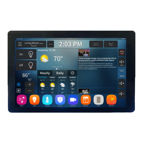
Firefly Integrations VEGATOUCH REV Discovery W/AH V3 Installation and operation manual

1
REV Discovery W/AH V3
GUI V2 LC
OEM Manual

2
REV Discovery with Aqua-Hot V3 OEM Manual
All information contained in this document is subject to change without notice.
2 Table of Contents
3 Lynx Screen Navigation
4 Home
Electrical
6 AC Power
7 IC Status
8 EMS Load Status
9 GEN AGS Options
10 GEN AGS Settings
11 GEN AGS Gen Setup
12 DC Power
13 IC Options
14 IC Battery Options
15 Lights
16 Climate Control
19 Fans
20 Settings
21 Additional Options
23 Mobile App
24 Vegatouch Module
25 Vegatouch Mira Setup
29 SSP18 Switch Panels
30 G6 Panel
31 Networking
32 Network Troubleshooting
33 System Diagrams
1013 Elroy Drive
Middlebury, Indiana 46540
Phone: (574) 825-4600
Support@Fireflyint.com

3
Lynx Screen Navigation
Tap any icon from the navigation menu to select the desired page. The currently selected page will
always be listed in the top corner of the screen. After 90 seconds of inactivity, the touch screen will
automatically change to the Lights page.
Home
Electrical
Lights
Climate
Fans
Settings

4
Home
Climate Control Status –The current temperature and
climate control mode for each zone will display on the
home screen. A white fan graphic will represent Fan
mode, a blue snowflake will represent Air
Conditioning, a red flame graphic will represent Aqua-
Hot and a Radiant Heat icon will represent Heat
Pump.
The Light Master controls all interior lights at once.
When Light Master Off is pressed, it will remember
which lights were on. Then, when Light Master On is
pressed, it will only turn on the lights that are in
memory. To turn on all lights again, press and hold
Light Master On for at least one second.
*Troubleshooting –Memory is rewritten each time
Light Master Off is pressed. In the case that it is
pressed twice in a row, it will remember that no lights
were on and just touching Light Master On won’t turn
on any lights. Press and hold Light Master On to turn
the lights back on.
After 90 seconds of inactivity, the touch screen will
automatically change to the Lights page.
Button feedback –most buttons will turn light blue when on and dark blue when off.
1
These graphics represent the percentage filled for
holding tanks.
Tap to select an Aqua-Hot heat source or toggle the
Water Pump On/Off.
1
2
2

5
AC Power- This section will give an overview of
the AC power information that is given from
your transfer switch and inverter.
DC Voltage –These graphics represent the
voltage available from your House and Chassis
batteries. The battery icons will display Green
above 12V and Red below 12V.

6
Electrical/AC Power
Shore Line Display –AC power displays the voltage,
amperage draw and frequency for each line.
Power Source Select –50 amp shore power will
display automatically if connected to a 50 amp line.
Tap to select 30, 20 or 15 amp if your coach is
connected to a 30 amp line.
Generator –Creates electrical energy. Press and hold
Start to start the generator. Tap Stop to stop the
generator.
AGS- Auto Gen Start is a system that will start the
generator automatically based on your customized
trigger settings (See page 9). Press to Enable/Disable
AGS. A warning page will appear requiring you to
press an additional Enable button for 3 seconds to
enable AGS. Only enable AGS if your coach is in a
well-ventilated area. Always DISABLE AGS before
plugging into shore power to keep your generator
from running unnecessarily.
Block Heater –Tap to toggle the Block Heater On/Off.
Screen Navigation Buttons
1
1
3
5
6
2
3
2
4
4
5
6

7
Electrical/AC Power/IC Status
DC and AC power information that is being received
by the Transfer Switch and Inverter.
This section will display any related faults and the
inverter bridge technical information.
1
1
2
2

8
Electrical/AC Power/EMS Load Status
Energy Management System (EMS) –EMS will ensure
that power is available before allowing certain systems
to run. If power is not available, it will not allow
particular systems to run (shed the load).
1
1

9
Electrical/AC Power/Gen AGS Options
Tap to Enable/Disable AGS.
Note, if enabling, a warning
screen will appear which will
require action to proceed. Press
and hold the Enable button for 3
seconds to enable AGS.
Trigger Options –Automatically start the generator
using specified voltage settings (Low Volts), when
Climate Control energy needs arise (HVAC Load), or
when Shore Power is insufficient. If no triggers are
selected, AGS will not run
Gen Hours Display - The number of hours that the
generator has been used. These hours are saved to
the system, not the generator itself. Press and Hold
for 5 seconds to change the generator display hours.
Quiet Time –Tap the buttons to select the hours that
your generator will not run, in an effort to reduce
noise.
1
1
2
2
Tap to navigate to the Gen Setup screen.
3
3
4
4

10
Electrical/AC Power/Gen Settings/AGS Settings
Start at Volts - The generator will start when the voltage drops
to this set point depending on “Time a Volts” setting below.
(Range 10.5v –12.5v)
Time at Start Volts - The generator will start when the voltage
drops to the Start at Voltage for this specific amount of time.
(Range 5 seconds –1 minute) 5 seconds –1 minute)
Stop at Volts - The generator will shut off when the voltage reaches
this set point depending on “Time at Stop Volts” setting below.
(Range 13.2v –14.5v)
Time at Stop Volts - The amount of time required for the voltage
to remain at “Stop at Volts” level before the generator shuts off.
(Range 5 Seconds –120 Seconds)
Minimum Gen Run Time - Use the +/- buttons to set the minimum
amount of time that your generator will run once it has started.
(Range 10min –30 min)0min –30min)
Maximum Gen Run Time - Use the +/- buttons to set the maximum
amount of time that your generator will run once it has started.
(Range 120min –240min)
(Range 120min –240min)
–30min)
Gen Start Retries - Use the +/- buttons to set the number of tries
that your generator will retry to start. (Range 2-5 retries)
–30min)

11
Electrical/AC Power/Gen AGS Options/Gen Setup
Tap the arrows to adjust the Max gen amps. This
setting should only be adjusted if the generator was
changed or upgraded.

12
Electrical/DC Power
These graphics represent the DC voltage available
from the House and Chassis batteries. They will
display Green above 12V and Red below 12V.
Inverter/Charger Amps and Charge Rate setting.
Tap the buttons to operate the Inverter or Charger.
1
1
2
2
3
3

13
Electrical/AC Power/IC Options
Low Battery Cutout –Tap the buttons to set the DC
Voltage level that turns off the inverter. This protects
the batteries from over-discharge damage.
VAC Dropout –Tap the buttons to set the minimum
AC voltage that must be present before the inverter
kicks off and switches the coach back to AC power.
Shore Breaker Size –Tap the buttons to adjust the
required shore power amp breaker setting.
Max Charge Rate –Tap the buttons to adjust amount
of available AC power that will be used for the
purpose of charging. This value should be kept low
when connected to shore power, or when there is a
high demand for energy.
2
3
4
1
1
2
3
4

14
Electrical/DC Power/IC Battery Options
Tap the buttons to select your required battery amp
hours.
Tap to select your required battery setting.
Please contact REV directly for recommended battery
settings.
1
2
2
1

15
Lights
This screen will control the lighting for the entire
coach, including the exterior. Tap any button to turn
the desired light On/Off.
Lights with up/down arrows are dimmable. Press and
hold these buttons to ramp the brightness up or
down. Tap the buttons to toggle On/Off.

16
*Selecting Cool, Heat Pump, Aqua-Hot or Auto will cause the respective buttons to change color.
Once a mode is chosen, either a Fan, Snowflake, Flame or Radiant Heat icon will appear above the
Current Temp to show which system is currently working.
Climate Control
Current Temperature by zone with climate
mode graphic and fan speed indicator.
Tap the arrows to select your desired
temperature, also known as Set Temp.
Cool –Tap to operate the air conditioning.
The A/C will run until the current temp
reaches your desired temp and then shut
off.
Heat Pump (Rear Zone Only) –Tap to
operate the heat pump. Heat Pump mode
has a Second Stage Heat feature that will
automatically enable the alternative heat
source (Aqua-Hot) if the Heat Pump cannot
bring the zone temp up to the set temp.
Aqua-Hot will enable if the zone temp
reaches 5°F below the set point.
Aqua-Hot –Tap to enable Aqua-Hot.
Tap to put the system into Auto Mode. The
A/C or Heat will automatically run to keep
your desired temperature consistent.
Fan Mode –The fan will operate by choosing
High or Low. Auto will turn the fan off. Fan
Mode is only available if HVAC is off. In cool
mode, fan speed can be set manually.
2
1
3
4
Aqua-Hot heat source selector.
Climate Zone navigation buttons.
5
1
2
3
4
5
6
6

17
Climate Control/Floor Heat Manual Mode
In Manual mode, tap the arrows to select
between 10 levels of floor heat.
Tap to enable/disable Manual or Schedule mode.
Tap to select a Floor Heat Zone.

18
Climate Control/Floor Heat Schedule Mode
Tap to enable/disable a schedule mode.
Tap to select between 10 levels of floor
heat.
Tap the buttons to select your desired
time period where floor heat will be
active.

19
Fans
Tap the Lid Arrow Up button to raise
the lid completely. If you do not
want to open the lid completely,
Press and Hold the button and
remove your finger when you would
like to stop the lid.
Tap the Power button to toggle the
fan On/Off. The power button color
will change to light blue while it is
on.
Tap the Lid Arrow Down button to
lower the lid completely. If you do
not want to lower the lid
completely, Press and Hold the
button and remove your finger
when you would like to stop the lid.
2
3
1
1
2
3

20
Settings
Note: Discovery with A/H GUI Version 3 will always use a Logic Controller Version 2.
Tap the buttons to select between 10 levels of screen
brightness and off.
Tap the Hour and Minute arrows to adjust the time.
Tap the Temperature Units display to toggle
between Fahrenheit and Celsius.
This box displays the Floorplan.
Cleaning Mode –Tap to disable the screen for 15
seconds for the purpose of cleaning.
Mobile App –Tap to enter the Vegatouch connection
screen.
Please have these version numbers available
before contacting Technical Support.
Table of contents
