Firefly Galleria User manual

1
\
Galleria/Crossfit/Beyond V4
Revision 2

2
The information contained in this manual is a general overview of the Firefly
system and is subject to change at any time.
2 Table of Contents
3 Lyra Screen Overview
4 Home
7 Lights
8 Auto Gen Start (AGS)
9 Climate Control
10 Settings
11 Settings/Mobile App
12 Vegatouch Mira Setup
16 Wireless Switch Pairing
17 Settings/Network Diagnostics
18 Settings/Manufacturer Options
19 G8 DC Panel
20 Networking
21 Network Status Indicators
22 Mira NET LED Status Key
23 System Diagrams

3
Tap any icon from the vertical navigation menu to select the desired page. The currently selected page
will always be listed in the top corner of the screen.
Home
Auto Gen
Lights
Climate
Settings
Lyra Screen Overview
Navigation Menu

4
The Light Master controls all interior lights at once. When Light Master Off is pressed, it will remember
which lights were on. Then, when Light Master On is pressed, it will only turn on the lights that are in
memory. To turn on all lights again, press and hold Light Master On for at least one second.
*Troubleshooting –Memory is rewritten each time Light Master Off is pressed. In the case that it is
pressed twice in a row, it will remember that no lights were on and just touching Light Master On won’t
turn on any lights. Press and hold Light Master On to turn the lights back on.
Awning –Press and hold EXT or RET to operate the awning (ignition must be off).
Set Temp –Tap the arrows to set your desired temperature.
Current temperature and current HVAC mode icons with fan speed indicator –A Blue Snowflake will
display for Air Conditioning and a White Fan graphic will display for Fan Only mode. H or L will indicator
the fan speed (High or Low).
2
2
1
1
4
3
3
4
Home

5
Water Tank Readings:
•9% and below will read “Empty” and
the tank level will show Empty.
•From 10% to 90%, the tank level and
percentage will show as normal.
•91% and above will read “FULL.” and
the tank shows accurate level.
LP Tank Readings:
•Below 25% will read “Low” and the
tank level will show as normal.
•From 25% to 75%, the tank level and
percentage will show as normal.
•From 75% to 96%, will read “Full” and
the tank level will show as normal.
•97% and above will read “Disc.” and
the tank level will be empty.
These graphics represent the holding tanks filled
status.
Propane % remaining.
Water Pump –Tap to toggle On/Off.
If the tanks are disconnected the readings will
display as shown.
FULL

6
AGS WARNING –to ensure safety, AGS will not be activated
until you hold the Enable button (from the Warning screen)
for at least 3 seconds.
Press and Hold the gen hours display
to enter the Set Gen Hours screen.
Tap the buttons to enter your desired
hours then tap Yes to save and exit.
House Voltage –the voltage
coming from your house
batteries. Note: Battery
graphics will display Red if
below 12V.
Chassis Voltage –the
voltage coming from your
engine battery.
Generator Start - hold Start to start
the generator (1 second delay).
Generator Stop –Hold Stop to stop
the generator.
Tap to Enable/Disable AGS.
5
If AGS is enabled before the coach is connected to shore
power, the Shore Override status message will be
displayed and AGS will be disabled. AGS will
automatically re-enable once shore power has been
disconnected.
5
6
6

7
This screen will control the lighting for the entire coach, including the exterior. Tap any button to turn
the desired light On/Off.
Lights with up/down arrows are dimmable. Press and hold these buttons to ramp the brightness up or
down. Tap the buttons to toggle On/Off.
Lights

8
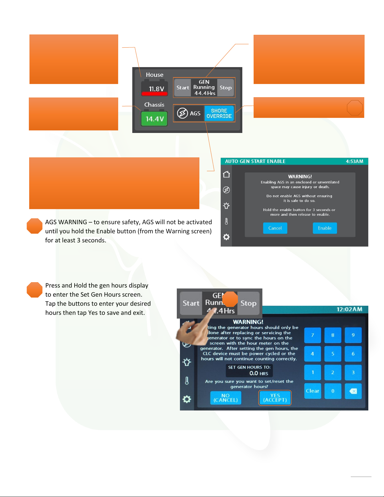
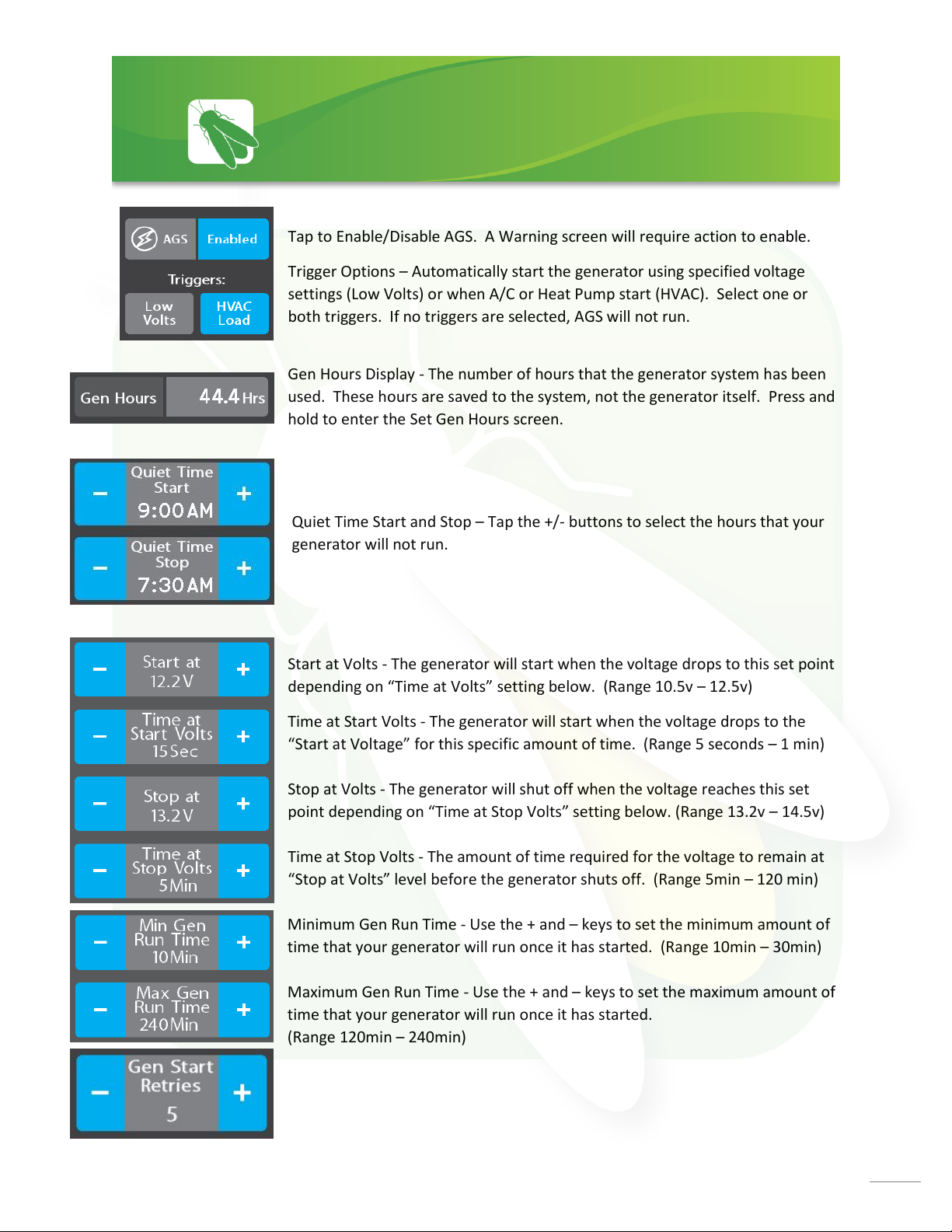
Tap to Enable/Disable AGS. A Warning screen will require action to enable.
Trigger Options –Automatically start the generator using specified voltage
settings (Low Volts) or when A/C or Heat Pump start (HVAC). Select one or
both triggers. If no triggers are selected, AGS will not run.
Gen Hours Display - The number of hours that the generator system has been
used. These hours are saved to the system, not the generator itself. Press and
hold to enter the Set Gen Hours screen.
Start at Volts - The generator will start when the voltage drops to this set point
depending on “Time at Volts” setting below. (Range 10.5v –12.5v)
Time at Start Volts - The generator will start when the voltage drops to the
“Start at Voltage”for this specific amount of time. (Range 5 seconds –1 min)
Stop at Volts - The generator will shut off when the voltage reaches this set
point depending on “Time at Stop Volts” setting below. (Range 13.2v – 14.5v)
Time at Stop Volts - The amount of time required for the voltage to remain at
“Stop at Volts” level before the generator shuts off. (Range 5min –120 min)
Minimum Gen Run Time - Use the + and –keys to set the minimum amount of
time that your generator will run once it has started. (Range 10min –30min)
Maximum Gen Run Time - Use the + and –keys to set the maximum amount of
time that your generator will run once it has started.
(Range 120min –240min)
Quiet Time Start and Stop –Tap the +/- buttons to select the hours that your
generator will not run.
Gen Start Retries –select the number of times that the generator will retry to
start if it fails to start on the first attempt.
Auto Gen Start (AGS)

9
Default Option
Tap the arrows to select your desired temperature (Set Temp). A Snowflake graphic with fan speed
indicator (H or L) will display during Cool mode.
Cool –Tap to operate the air conditioning. The A/C will run until the current temp reaches your desired
temp and then shut off.
ProAir Option
In this option, tap Auto to have the system automatically control the fan speed, or drag the slider to
select a fan speed percentage. There will be no H or L fan speed graphic in this mode.
Fan Mode –The fan will operate by choosing High or
Low. Auto will turn the fan off. If Cool has not been
selected, the fan speeds will enable Fan Only mode.
1
1
Climate Control

10
Settings
1
2
3
4
6
5
7
8
9
Tap to navigate to the Vegatouch Mira connection screen.
Tap to navigate to the Network Diagnostics screen.
1
2
3
Tap to navigate to the Manufacturer Options screen.
4
Wireless switch panel display status
5
Tap to select between Fahrenheit and Celsius.
Drag the Slider to adjust screen brightness.
6
When Auto Dimming is enabled, the screen will enter sleep mode after 60 seconds of inactivity. Tap anywhere
on the screen to wake it up. Please note that even if Auto Dimming has been disabled, the screen will still enter
sleep mode after 4 hours of inactivity during daytime hours (5am –10:59pm) and after 15 minutes of inactivity
during night time hours (11pm-4:59am) as the result of a built in screen saver that cannot be disabled.
7
Tap to disable the touchscreen for 15 seconds for the purpose of cleaning.
Tap the buttons to set the time or select 24-hour time mode.
8
9
Please note the GUI and Logic Controller Versions and have these numbers available before contacting Tech Support.

11
Vegatouch Mira is a wireless control module that easily connects to any Android or iOS device
to give total control to many electrical, electronic and mechanical systems in your coach. Pair
any device with the coach’s built-in interface to monitor and control many coach components.
Settings/Mobile App

12
Notice: Make sure that Bluetooth is turned ON in your smart device
settings before proceeding.
Locate the Login Information:
The login information can be found by
clicking on the Mobile App button on
the settings page of the touchscreen
or from the Mira module’s label.
Download:
Download Vegatouch Mira from the Google Play store or the App Store.
Once the download has finished, install the app and open it.
Setup:
Tap SCAN to find the Mira Module’s signal. After scanning, any Mira Module in your area will
appear on the screen. Tap the ID # that matches the one on your Mira label. Enter the PIN
number from the Mira label and press AUTHENTICATE to connect to the system.
Vegatouch Mira Setup

13
Notice: iOS Setup Tips
Turn on Bluetooth to allow Vegatouch Mira to
connect to Accessories.
If you do not have Bluetooth turned ON in your iOS settings
you will see this screen. Do not click OK, you must click
SETTINGS. Your Bluetooth Settings page will now appear and
you should turn Bluetooth ON.
Notice: Android Setup Tips
Allow Vegatouch Mira to access this device’s location.
Mira will need to be allowed access to your location. Click ALLOW when you see this
screen.

14
App Settings:
Access the App Settings page by tapping the triangle (at the bottom of the screen) to expose the
Settings button. Tap the gear to visit the settings page.
Tap to Temperature Units selection to
choose between Fahrenheit and Celsius.
System Information and Mira Name.
Tap to disconnect your device from Mira.
Tapping Update Config will force a
download of the config from the cloud.
Tap to enter the Diagnostic Tools screen.

15
Diagnostic Tools:
Tap to display a list of currently
connected devices.
Remote Help is available by calling Firefly
Integrations. Do not enable remote help
without consultation.

16
The switch Battery Graphic will identify the status of the wireless switch panel.
Green battery switch indicator –the switch is currently conencted to the screen.
Red battery switch indicator - The switch is currently disconnected from the screen. It is likely that the
battery inside your switch panel needs replaced. The wireless switch panel in your coach will illuminate
a green LED whenever a button is pressed. If the LED on your switch panel does not illuminate when
you press a button on your switch, you will need to replace the 2032 coin cell battery.
If a new battery will not fix the issue, you might need to pair the switch panel to the screen.
Press and Hold the battery graphic for 3 seconds until the pairing screen appears.
Tap Start Pairing. You’ll have 30 seconds to press any 2 buttons on the switch panel at the same time.
Tap Done once the pairing successful message appears. It may take up to 10 minutes for the wireless
switch indicator to turn Green, but the switch should work instantly once paired.
1
2
3
Wireless Switch Pairing
2
2
Time Remaining
1
3

17
Devices/Inputs
The Network Diagnostics screen will display the status of the touchscreens, the G8 panel and the Aircon.
It will also identify any currently active faults.
G8 Outputs
This screen will identify which individual G8 outputs are currently active.
Green = Online
Settings/Network Diagnostics
Green = Active

18
Tap the squares to enable or disable the options required for your specific vehicle.
Settings/Manufacturer Options

19
The G8 control DC Panel receives the signals sent from your switch panels and
performs the actions that have been requested by activating and deactivating
the required circuits.
Every circuit controlled by the G8 is numbered and listed on a black label (load
list) which is usually mounted next to the G8 panel.
A corresponding numbered LED will illuminate
green whenever a particular circuit is on. For instance, if
you press the Bath Light button on your switch panel, the
green LED for output 11 will illuminate and the Bath Light
will turn on (Fig 3).
Testing output voltage using a Multi-meter.
Ensure that the G8 circuit is on and that the corresponding green LED is illuminated.
To test the output voltage for the Ceiling Lights example, touch the positive lead to the output
pin for output 11 (Connector J9 –Pin 1) and the negative lead to the ground stud (as pictured
below).
G8 DC Panel
Fig 3
Fig 4A
NET LED
GROUND
Test Positive Output Channels as shown:
Multi-
meter

20
Your distribution panel and touchscreens are connected via your coach’s RV-C network. Each
component will have a NET LED that is used to show network status. If a NET LED is displaying
anything other than solid green and some of the panel’s functions are not working, please
contact your manufacturer for Technical Support.
Net LED Locations:
Back of
Touchscreens
Networking
G8
This manual suits for next models
3
Table of contents
Other Firefly Automobile Accessories manuals