Firegear AF-1100 VALVE SERIES User manual

1
INSTALLATION AND
OPERATION INSTRUCTIONS
FIREGEAR REVOLUTION UNVENTED GAS
LOG HEATER & VENTED DECORATIVE
GAS LOG HEARTH KIT – ON / OFF REMOTE
AF-1100 VALVE SERIES
If for any reason, you cannot follow these instructions, FOR
ANY REASON WHATSOEVER, just return the product to your
dealer, and the dealer will refund your money. “PLEASE” do
not use this product if you cannot follow these instructions.
CONGRATULATIONS, on the purchase of your new firegear
REVOLUTION VENTED / UNVENTED GAS LOG HEATER.
GENERAL INFORMATION
These instructions are intended as a general guide and do not
supersede national or local codes in any way. State or local
codes may only allow operation of this appliance in a vented
configuration. Check your state or local codes. Authorities
having jurisdiction should be consulted before installation.
Installation and provision for combustion and ventilation air
must conform to the National Fuel Gas Code, ANSI
Z223.1/NFPA 54, or CAN/CGA-B149.1,Natural Gas
Installation Code, or CAN/CGA-B149.2,Propane Installation
Code.
This appliance has been tested to, and complies with, ANSI
Z21.11.2 (2002), Standard for Gas-Fired Unvented Room
Heaters, & ANSI Z21.60 ( 2003 ) and CAN/CGA 2.26 ( 2003 ),
Standards For Decorative Gas Appliances For Installation In
Solid-Fuel Burning Fireplaces.
!!! IMPORTANT !!!
Read these instructions carefully before installing or operating
this gas appliance. These instructions should be left with the
homeowner for future reference.
INSTALLER: Leave this manual with the appliance.
CONSUMER: Retain this manual for future reference.
!!! WARNING !!!
If the information in this manual is not followed exactly, a fire or
explosion may result causing property damage, personal injury
or loss of life.
This is an un-vented gas-fired heater. It uses air ( Oxygen )
from the room in which it is installed. Provisions for adequate
combustion and ventilation air must be provided. Refer to
section “ PROVISIONS FOR ADEQUATE COMBUSTION &
VENTILATION AIR “ on page 6.
This appliance may be installed in an aftermarket, permanently
located manufactured ( mobile ) home, where not prohibited by
local codes.
This appliance is only for use with the type of gas indicated on
the rating plate. This appliance is not convertible for use with
other gases.
TABLE OF CONTENTS
GENERAL INFORMATION 1
MODELS 2
SHIPPING AND PACKING LIST 2
SAFETY INFORMATION 2
SPECIFICATIONS 3
CLEARANCES 4
PROVISIONS FOR COMBUSTION & AIR 6
INSTALLATION 7
SET-UP & ASSEMBLY 8
OPERATION 14
LIGHTING INSTRUCTIONS 15
MAINTENANCE & SERVICE 16
CURING REFRACTORY LOGS 16
PARTS LISTING 17
TROUBLE SHOOTING 21
WARRANTY 22
WHAT TO DO IF YOU SMELL GAS:
< Do not try to light any appliance.
< Do not touch any electrical switch; do not use
any phone in your building.
< Immediately call your gas supplier from a
neighbor’s phone. Follow the gas supplier’s
instructions.
< If you can not reach your gas supplier, call the
fire department.
Do not store combustible materials or use gasoline
or other flammable vapors and liquids in the vicinity
of this or any other appliance.
Installation and service must be performed by a:
Qualified technician, service agency, or the gas
supplier.
15LP REVA11 – 3.4
ANSI Z21.11.2
–
(2002) STANDARD FOR GAS
-
FIRED
UNVENTED ROOM HEATERS (US ONLY) & ANSI Z21.60 -
(2003) / CGA 2.26 - (2003) STANDARD FOR DECORATIVE
GAS APPLIANCES FOR INSTALLATION IN SOLID-FUEL
BURNING FIREPLACES (US & CANADA). 15LP

2
FIREGEAR REVOLUTION VENTED &
UNVENTED HEARTH KIT MODELS
ON / OFF REMOTE
MODEL DESCRIPTION
B360M11-N Manual Valve Natural Gas
B360M11-P Manual Valve Liquid Propane
B420M11-N Manual Valve Natural Gas
B420M11-P Manual Valve Liquid Propane
B360A11-N On / Off Remote Valve Natural Gas
B360A11-P On / Off Remote Valve Liquid Propane
B420A11-N On / Off Remote Valve Natural Gas
B420A11-P On / Off Remote Valve Liquid Propane
B360A11-N-T On / Off Remote Valve Natural Gas
with Thermo Remote
B360A11-P-T On / Off Remote Valve Liquid Propane
with Thermo Remote
B420A11-N-T On / Off Remote Valve Natural Gas
with Thermo Remote
B420A11-P-T On / Off Remote Valve Liquid Propane
with Thermo Remote
Hearth Kit Models are to be used with the following FIREGEAR
Log Sets:
L-360-CD L-420-CD CD
L-360-BY L-420-BY BIG Y
L-360-RR L-420-RR ROARING RED
L-360-BH NA BIG HORN 12
SHIPPING AND PACKING LIST
Your FIREGEAR REVOLUTION VENTED / UNVENTED GAS
LOG HEARTH KIT comes assembled, ready for the gas
connection, with the exception of ember material and log
placement.
SHIPPING CARTONS CONTAIN:
Box One: Hearth Kit
1- Revolution Burner Including Grate/Burner Assembly with
Valve, Regulator & Safety Pilot
1- Bag – Lava Rock ( cinders )
1- Bag – Glowing Embers
1- Damper Clamp Assembly ( vented applications )
1- Manual Pack with Warranty Card
Box Two: Decorative Gas Logs
8 to 11 Decorative Accent Logs
1- Log Placement Manual
1- Log Placement Plate
OPTIONAL ACCESSORIES:
( included on some models )
1- Remote Control or Thermo Remote Control
SEE ACCESSORIES AVAILABLE STARTING ON PAGE 20.
GENERAL SAFETY INFORMATION
<WARNING: Follow all gas leak check procedures in this
manual, prior to operation.
<WARNING: Fuels used in gas or oil – fired appliances,
and the products of combustion of such fuels, contain
chemicals known to the State of California to cause
cancer, birth defects, and/or other reproductive harm.
This warning is issued pursuant to California Health &
Safety Code Sec. 25249.6.
< While this appliance is not in use, the gas must be turned
off at the gas supply.
< DO NOT ATTEMPT TO DISCONNECT THE GAS OR
ANY GAS FITTING WHILE THIS APPLIANCE IS IN
OPERATION.
< NEVER leave this appliance unattended while in
operation.
< NEVER allow children to operate this appliance.
< NEVER place hands or fingers on the front edge of this
appliance.
< NEVER use liquid propane gas in a natural gas unit, or
natural gas in a liquid propane unit.
< DO NOT use solid-fuel, or lighter fluid in any gas
appliance.
< Keep appliance area clear and free from combustible
materials, gasoline, and other flammable vapors and
liquids.
SAFETY INFORMATION PERTINENT TO
UNVENTED APPLICATIONS
Due to high temperatures, the appliance should be located out
of traffic and away from furniture and draperies.
Children and adults should be alerted to the hazard of high
surface temperature and should stay away to avoid burns or
clothing ignition.
Young children should be carefully supervised when they are
in the same room with the appliance.
DO NOT place clothing or other flammable material on or near
the appliance.
Any safety screen or guard removed for servicing an appliance
must be replaced prior to operating the heater. Fireplace
screens must be closed while the appliance is in operation.
Installation and repair should be done by a qualified service
person. The appliance should be inspected before use and at
least annually by a professional service person. More frequent
cleaning may be required due to excessive lint from carpeting,
bedding material, etc. It is imperative that control
compartments, burners and circulating air passageways of the
appliance be kept clean.

3
SAFETY INFORMATION PERTINENT TO
UNVENTED APPLICATIONS continued
WARNING: Any modification to this heater or its controls can
be dangerous.
DO NOT INSTALL HEATER UNTIL ALL NECESSARY
PROVISIONS ARE MADE FOR COMBUSTION AND
VENTILATION AIR. CONSULT THE WRITTEN
INSTRUCTIONS PROVIDED WITH THE HEATER FOR
INFORMATION CONCERNING COMBUSTION AND
VENTILATION AIR. IN THE ABSENCE OF INSTRUCTIONS,
REFER TO THE NATIONAL FUEL GAS CODE, ANSI Z223.1,
SECTION 5.3 OR APPLICABLE LOCAL CODES.
This heater is equipped with an ODS ( Oxygen Depletion
Sensor ) SAFETY PILOT SYSTEM designed to turn off the
heater if not enough fresh air is available.
DO NOT TAMPER WITH SAFETY PILOT SYSTEM!
If the heater shuts off, DO NOT re-light until you have provided
fresh air to the appliance.
If heater keeps shutting off, have it serviced. Keep burner and
control compartment clean.
CARBON MONOXIDE POISONING MAY LEAD TO DEATH
Early signs of carbon monoxide poisoning resemble the flu,
with headache, dizziness and/or nausea. If you have these
symptoms, heater may not be working properly.
GET FRESH AIR AT ONCE! HAVE HEATER SERVICED!
Some people – pregnant women, persons with heart or lung
disease, anemia, those under the influence of alcohol, those at
high altitudes – are more affected by carbon monoxide than
others.
!!! WARNING !!!
Improper installation, adjustment, alteration, service or
maintenance, can cause property damage, personal injury or
loss of life. Refer to the owner’s information manual, provided
with this appliance. Installation and service must be performed
by a qualified installer, service agency or the gas supplier.
!!! WARNING !!!
When used without adequate combustion and ventilation air,
heater may give off excessive CARBON MONOXIDE, an
odorless, poisonous gas.
!!! WARNING !!!
Before you install this appliance, have a professional installer
audit the conditions of combustion and ventilation air.
Additional ventilation may be required in conditions of tight
construction.
FIREGEAR REVOLUTION FG-360A11 GAS
LOG HEARTH KIT SPECIFICATIONS
NATURAL GAS - RATED PRESSURE – 3.5” W.C.
MINIMUM GAS MAXIMUM GAS ORIFICE BTU/HR
PRESSURE PRESSURE SIZE INLET
4.5” W.C. 10.5” W.C. #37 29,000
Operating Pressure of Regulator per rate – 3.5” W.C.
LIQUID PROPANE - RATED PRESSURE – 10.0” W.C.
MINIMUM GAS MAXIMUM GAS ORIFICE BTU/HR
PRESSURE PRESSURE SIZE INLET
11.0” W.C. 13.0” W.C. #53 24,000
Operating Pressure of Regulator per rate – 10.0” W.C.
FIREGEAR REVOLUTION FG-420A11 GAS
LOG HEARTH KIT SPECIFICATIONS
NATURAL GAS - RATED PRESSURE – 3.5” W.C.
MINIMUM GAS MAXIMUM GAS ORIFICE BTU/HR
PRESSURE PRESSURE SIZE INLET
4.5” W.C. 10.5” W.C. #35 32,000
Operating Pressure of Regulator per rate – 3.5” W.C.
LIQUID PROPANE - RATED PRESSURE – 10.0” W.C.
MINIMUM GAS MAXIMUM GAS ORIFICE BTU/HR
PRESSURE PRESSURE SIZE INLET
11.0” W.C. 13.0” W.C. #52 28,000
Operating Pressure of Regulator per rate – 10.0” W.C.
HIGH ALTITUDE DERATE
In the U.S.A., input BTU shall be de-rated 4% ( 1 orifice
size ) per 1000 ft. for altitudes above 2000 ft.. In
Canada, input BTU shall be de-rated 10% ( 2 orifice
sizes ) at altitudes from 2000 ft. to 4500 ft..
MINIMUM FIREPLACE DIMENSIONS
MASONRY BUILT FIREPLACES
Chimney Height minimum of 6 feet – Vented Applications
LOG FRONT DEPTH HEIGHT MINIMUM
SET WIDTH IN IN IN VENT IN
SIZE INCHES INCHES INCHES SQ INCHES
FG-360A11 30" 14" 19" 25.7 sq. in.
FG-420A11 36" 14" 20" 33.8 sq. in.

4
MINIMUM FIREPLACE DIMENSIONS
continued
MINIMUM FIREPLACE DIMENSIONS
FACTORY BUILT FIREPLACES
Chimney Height minimum of 10 feet – Vented Applications
LOG FRONT DEPTH HEIGHT MINIMUM
SET WIDTH IN IN IN VENT IN
SIZE INCHES INCHES INCHES SQ INCHES
FG-360A11 30" 14" 19" 16.6 sq. in.
FG-420A11 36" 14" 20" 22.1 sq. in.
CLEARANCES FOR UNVENTED APPLICATIONS
PROPER CLEARANCES FROM COMBUSTIBLE
CONSTRUCTION AND MATERIALS MUST BE MAINTAINED
FROM ALL SIDES, TOP, AND BOTTOM OF THIS
APPLIANCE.
THIS APPLIANCE SHOULD NEVER BE PLACED NEAR
ANY COMBUSTIBLE SURFACE.
THIS APPLIANCE SHOULD NEVER BE PLACED UNDER
ANY COMBUSTIBLE CONSTRUCTION OR MATERIALS.
MINIMUM DIMENSIONS – SOLID-FUEL BURNING & UL 127
FACTORY BUILT FIREPLACES ( SEE FIGURE 1 )
LOG REAR DEPTH FRONT HEIGHT
SET WIDTH IN IN WIDTH IN IN
MODEL INCHES INCHES INCHES INCHES
A B C D
FG-360A11 21.5” 14" 30” 19”
FG-420A11 26” 14" 36” 20”
FIGURE 1
The dimensions shown and defined in the fireplace
manufacturer’s instructions, are the minimum clearances that
must be maintained, when installing this appliance.
Follow these instructions to insure safe installation. Failure to
follow these instructions exactly, can create a fire hazard.
SIDEWALL & CEILING CLEARANCES
FIGURE 2
The sides of the fireplace opening must be a minimum of six
( 6” ) inches from any combustible wall material.
The ceiling must be a minimum of forty-two ( 42” ) inches from
the fireplace opening. ( SEE FIGURE 2 )
MANTEL CLEARANCES WITHOUT HOOD
You must have non-combustible material above the fireplace
opening. Non-combustible material must extend a minimum of
twelve ( 12” ) inches above the fireplace opening. When
using sheet metal, you must have non-combustible material
behind it. ( SEE FIGURE 3 )
Heat resistant materials, such as slate and marble, must be at
least ½” thick. Sheet metal should NOT be installed onto
combustible material. ( SEE FIGURE 3 )
!!! WARNING !!!
If you can not meet these minimum clearances, you MUST
operate this appliance with the chimney flue damper open, OR
you must use a hood. See instructions for vented operations.
Material Distance Safe Installation
12” or more Non-combustible material
Less than 12” Non-combustible material must be
extended to at least 8” with the
installation of the optional fireplace
hood. If you can not extend non-
combustible material at least 8”,
you must operate heater with the
chimney flue damper open.

5
MANTEL CLEARANCES WITHOUT HOOD continued
MANTEL WITHOUT HOOD
FIGURE 3
MANTEL CLEARANCES WITH HOOD
FIGURE 4
A mantel may project from the wall a maximum of two ( 2” )
inches, at a minimum of thirteen and one-half ( 13 ½” ) inches,
above the fireplace opening, and a maximum of six ( 6” )
inches, at a minimum of fifteen ( 15” ) inches, above the
fireplace opening. ( SEE FIGURE 4 )
!!! WARNING !!!
If your installation does NOT meet the minimum clearances,
you MUST:
1- Operate this appliance with the chimney flue damper
open; or
2- Raise the mantel to the proper height; or
3- Remove the mantel.
FLOOR CLEARANCES
If installing the appliance at floor level, the minimum clearance
to combustible material is six ( 6” ) inches. ( SEE FIGURE 5 )
FIGURE 5
EXAMPLE OF COMBUSTIBLE MATERIAL
DO NOT attach any combustible materials to the mantel of
your fireplace. This is a FIRE HAZARD! ( SEE FIGURE 6 )
FIGURE 6
DO NOT attach greeting cards, stockings, or any type of
ornamentation to the mantel or fireplace. This is a heating
appliance; the flow of heat can ignite combustible material.
( SEE FIGURE 7 )
FIGURE 7
HEAT RESISTANT
MATERIAL 12” WITHOUT
HOOD
HEATER IN FIREPLACE
OR FIREBOX
28”
12”
HEAT RESISTANT
MATERIAL 8” WITH
HOOD
HEATER IN
FIREPLACE
OR FIREBOX
HOOD
8” Mantel
6” Mantel
4” Mantel
2” Mantel
14.25”
13.5”
15”
16”
6” COMBUSTIBLE
MATERIAL
HEATER IN
FIREPLACE

6
PROVISIONS FOR ADEQUATE
COMBUSTION & VENTILATION AIR
IN UNVENTED APPLICATIONS
This heater shall not be installed in a confined space or
unusually tight construction, unless provisions are provided for
adequate combustion and ventilation air.
The National Fuel Gas Code, ANSI Z223.1/NFPA 54 defines a
confined space as a space whose volume is less than 50 cubic
feet per 1,000 Btu per hour ( 4.8 m3per kw ) of the aggregate
input rating of all appliances installed in that space and an
unconfined space as a space whose volume is not less than 50
cubic feet per 1,000 Btu per hour ( 4.8 m3per kw ) of the
aggregate input rating of all appliances installed in that space.
Rooms communicating directly with the space in which the
appliances are installed, through openings not furnished with
doors, are considered a part of the confined space.
FIGURE 8 – ROOM EXAMPLE WITH DIVIDER
The following formula can be used to determine the maximum
heater rating per the definition of unconfined space:
WARNING: If the area in which the heater may be operated is
smaller than that defined as an unconfined space, or if the
building is of unusually tight construction, provide adequate
combustion and ventilation air by one of the methods
described in the National Fuel Gas Code, ANSI Z223.1/NFPA
54, Section 5.3 or applicable local codes.
Unusually tight construction is defined as construction where:
a) Walls and ceilings exposed to the outside atmosphere
have a continuous water vapor retarder with a rating of 1
perm ( 6 X 10-11 kg per pa-sec-m2) or less with openings
gasketed or sealed;
b) Weather stripping has been added on openable windows
and doors;
c) Calking or sealants are applied to areas such as joints
around window and door frames, between sole plates and
floors, between wall-ceiling joints, between wall panels, at
penetrations for plumbing, electrical, and gas lines, and at
other openings.
An unvented room heater having an input rating of more than
10,000 Btu per hour shall not be installed in a bedroom or
bathroom; or
An unvented room heater having an input rating of more than
6,000 Btu per hour shall not be installed in a bathroom.
INSTALLATION INFORMATION
UNVENTED APPLICATIONS
!!! WARNING !!!
This appliance is for installation only in a solid-fuel burning
masonry or UL 127 factory-built fireplace or in a listed ventless
firebox enclosure. It has been design certified for these
installations. EXCEPTION: DO NOT install this appliance in a
factory-built fireplace that includes instructions stating that it
has not been tested or should not be used with unvented gas
logs.
!!! WARNING !!!
Any modification to this unvented gas heater, or its controls,
can be dangerous. Improper installation or use of the heater
can cause serious injury or death from fire, burns, explosion, or
carbon monoxide poisoning.
!!! WARNING !!!
Solid-fuels shall not be burned in a fireplace where an
unvented room heater is installed.
WARNING: This installation is NOT complete until floor
protector ( if applicable ) is installed.
WARNING: DO NOT allow fans to blow directly into the
fireplace. Avoid any drafts that alter burner flame patterns.
WARNING: DO NOT use a blower insert, heat exchanger
insert, or other accessory, not approved for use with this
heater.
Unvented gas heaters are a supplemental source of heat; they
are not intended to be primary heating appliances. Water
vapor is a by-product of gas combustion, and as produced by
an unvented heater, can create moisture problems in homes,
when operated for extended periods of time. If high humidity is
experienced, a dehumidifier may be used to lower the water
vapor content of the air.
During manufacturing, fabrication, and shipping, various
components of this appliance are treated with certain oils,
films, or bonding agents. These chemicals ARE NOT harmful,
but may produce annoying smoke and smells, as they are
burned off, during the initial operation of the appliance. This
may possibly cause headaches, and eye or lung irritation. This
is a normal and temporary occurrence. The initial break-in
period should last three ( 3 ) to four ( 4 ). During this period,
provide maximum ventilation by opening a window or door, to
allow odors to dissipate. Any odor remaining after this initial
break-in period, will be slight and will disappear with continued
use.

7
CLEARANCES FOR VENTED APPLICATIONS
PROPER CLEARANCES FROM COMBUSTIBLE
CONSTRUCTION AND MATERIALS MUST BE
MAINTAINED FROM ALL SIDES, TOP, AND BOTTOM
OF THIS APPLIANCE.
THIS APPLIANCE SHOULD NEVER BE PLACED
NEAR ANY COMBUSTIBLE SURFACE.
THIS APPLIANCE SHOULD NEVER BE PLACED
UNDER ANY COMBUSTIBLE CONSTRUCTION OR
MATERIALS.
NEVER PLACE ANY COMBUSTIBLE MATERIAL
WITHIN TWENTY-FOUR ( 24” ) FROM THE FRONT
OF THE FIREPLACE ENCLOSURE.
FIGURE 9
!!! WARNING !!!
FOR VENTED APPLICATIONS: The damper clamp must be
installed in a manner, which will maintain the minimum
permanent damper vent opening at all times. SEE FIGURE 9.
See the Decorative Gas Log Set Specifications on page 3 & 4.
!!! WARNING !!!
The State of Massachusetts requires that the chimney flue
damper, when used with decorative gas log sets, be welded
open or completely removed. In the Commonwealth of
Massachusetts, this appliance must be installed by a licensed
plumber or gasfitter.
!!! WARNING !!!
FOR VENTED APPLICATIONS: This appliance, must be
installed only in a solid-fuel burning fireplace with a working
flue and constructed of noncombustible materials. This unit is
NOT for use with solid fuel. Solid fuels shall NOT be burned in
a fireplace where a decorative gas appliance is installed.
INSTALLATION
Installation will be much easier if two ( 2 ) or more people co-
operate in locating and installing the unit.
LOCATION
FOR VENTED APPLICATONS: This appliance must be
installed only in a solid-fuel burning fireplace, with a working
flue, and constructed of noncombustible materials.
!!! WARNING !!!
Gas supply system must be installed in accordance with the
U.S. National Fuel Gas Code.
This appliance and its individual shut off valve must be
disconnected from the gas supply piping system during any
system pressure test in excess of ½ PSI ( 3.5 KPA ).
Use a system manual shut off valve to shut off the gas supply
to this gas appliance before continuing with installation
procedures.
!!! IMPORTANT !!!
FOR VENT-FREE APPLICATIONS: If the appliance is to be
installed in a solid-fuel burning fireplace, have the fireplace and
chimney, professionally cleaned, to remove any ashes, soot,
creosote, or loose debris. The fire box must be sealed from
any potential drafts, from cleanouts, ill-fitting dampers, cracks,
etc…
!!! IMPORTANT !!!
FOR VENT-FREE APPLICATIONS: Seal any fresh air vents or
ash clean-out doors located on the floor or wall of the fireplace.
If this is not performed, drafting may cause pilot outage or
sooting. Use a heat-resistant sealant. SEAL THE DAMPER,
ONLY IN VENT-FREE APPLICATIONS!
!!! IMPORTANT !!!
FOR VENTED APPLICATIONS: Before installing this
appliance, have the fireplace and chimney, professionally
cleaned, to remove any ashes, soot, creosote, or other
obstructions. Perform this cleaning annually, after installation.
!!! IMPORTANT !!!
FOR VENTED APPLICATIONS: Seal any fresh air vents or
ash clean-out doors located on the floor or wall of the fireplace.
If the above conditions are not met, drafting may cause pilot
outage or sooting. Use a heat-resistant sealant; DO NOT seal
the chimney flue damper.
!!! IMPORTANT !!!
Decorative Gas Log Sets are shipped with the appropriate gas
connections for each type of gas, i.e., Natural Gas or Liquid
Propane. If you have purchased an inappropriate unit for your
application, contact your retailer, installer, or the firegear
Customer Service Center.
WARNING: This appliance is equipped for ( Natural or
Propane ) gas. Field conversion is not permitted.

8
INSTALLATION continued
FIGURE 10 – REVOLUTION BURNER ASSEMBLY FRONT VIEW
FIGURE 11 – REVOLUTION BURNER ASSEMBLY ANGLE VIEW
WHEN INSTALLING THE APPLIANCE, DO NOT OBSTRUCT THE FLOW OF COMBUSTION AND VENTILATION AIR.
SET UP AND ASSEMBLY
Your FIREGEAR REVOLUTION VENTED / UNVENTED GAS
LOG HEARTH KIT comes assembled, ready for the gas
connection, with the exception of ember material and log
placement.
!!! IMPORTANT !!!
BEFORE YOU BEGIN – Audit the gas pressure, at the
fireplace stub, to insure proper, minimum gas pressure; see
the specifications, beginning on page 3 of this manual.
!!! IMPORTANT !!!
BEFORE YOU BEGIN – Insure that the fire box meets the
minimum specifications of the appliance; see the specifications
beginning on page 3 of this manual.
!!! IMPORTANT !!!
This appliance, when first installed, may produce unpleasant
odors; these will gradually diminish.

9
SET UP AND ASSEMBLY continued
1- Remove all contents from the Hearth Kit shipping container.
( Box One )
2- Check the contents of the shipping container against the
shipping and packing list, or the parts list in this manual.
Report any missing or damaged parts to your retailer.
3- Remove any and all protective wrapping from the appliance.
TOOLS THAT YOU WILL NEED
2- Adjustable wrenches; at least one of which has a range
of 3/4" ( for gas fittings )
2- Adjustable Pipe Wrenches
1- 3/8” Nut Driver or socket ( for damper clamp )
1- TURN OFF THE GAS SUPPLY SYSTEM!
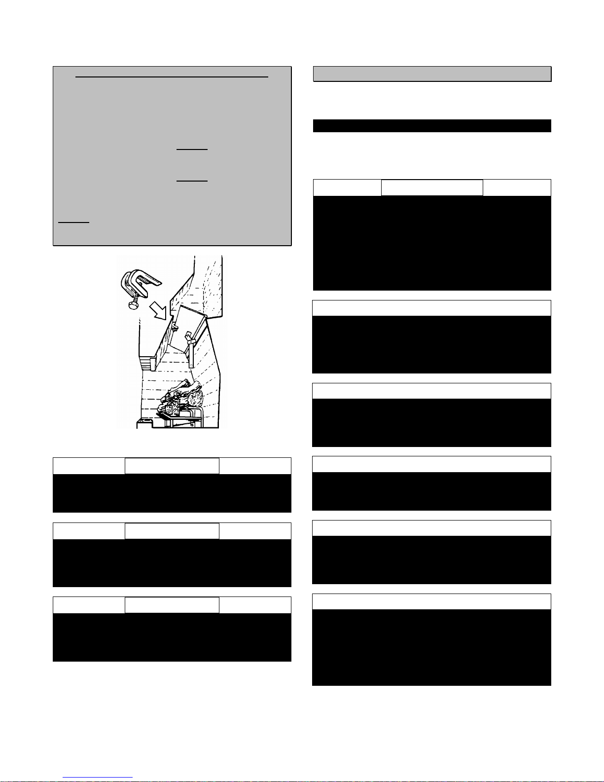
2- FOR VENTED APPLICATIONS: Place the fireplace damper
in the fully open position, and install the damper clamp over
the lip of the damper ( The damper must be in a fully open
position, any time that this appliance is in operation ).
Using a 3/8” nut driver or socket, and turning in a clockwise
direction, tighten the damper clamp bolt until the clamp is
secure. The damper clamp must be in place to maintain the
minimum permanent vent opening. See the chart “ MINIMUM
FIREPLACE DIMENSIONS “ on page 3 & 4, for correct
venting. ( SEE FIGURE 9, page 7 )
NOTE: The State of Massachusetts requires that the chimney
flue damper, when used with decorative gas log sets, be
welded open or completely removed.
3- Using two adjustable pipe wrenches ( one wrench on the gas
stub, and one wrench on the fitting ), remove the existing cap
or gas jet assembly from the gas stub in your fireplace, by
turning the wrench on the gas cap, in a counter-clockwise
direction.
4- Clean the pipe threads, on the gas stub, using either, a wire
brush or steel wool. Apply Teflon tape or pipe dope to the
steel fittings before making any connection.
NOTE: All gas connections ( except for brass to brass )
require Teflon tape or pipe dope.
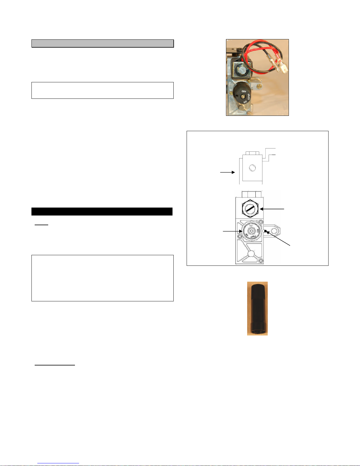
5- Place the appliance into the fireplace ( unit is packaged as a
single burner assembly; grate, valve/regulator assembly, and
burner ). The unit should be centered from both side to side,
and front to back. The unit is shipped, ready for rear gas
connection only. ( SEE FIGURE 10 & 11 )
6- FOR UNVENTED APPLICATIONS: You must secure the
appliance to the floor of the fireplace. This must be done to
prevent movement of the appliance during adjustment of
controls. Movement of the appliance may cause a gas leak,
improper positioning of gas logs, and/or improper combustion
and sooting. ( SEE FIGURE 12 )
NOTE: Special care is required if you are installing the
appliance into a sunken fireplace. The fireplace floor must be
raised, using non-combustible materials, to allow access to
the controls. This will also insure proper air flow to the
appliance.
A) After centering the appliance correctly, and using the
grate leg fasteners as a guide, mark the hole positions on the
fireplace / firebox floor. Drill two ( 2 ) 5/32” diameter holes,
approximately 1 ½” deep for masonry screws ( not included ),
or 1/8” deep holes for sheet metal screws ( not included )
( SEE FIGURE 12 )
B) Affix the appliance to the fireplace / firebox floor using the
appropriate screws.
FIGURE 12
Proper installation of the appliance is essential to prevent
any movement of the gas logs and controls during
operation.
7- Bend a 3/8” gas line, with two ( 2 ) 3/8” brass, female flare
fittings ( not included ), to facilitate the gas connection,
between the valve/regulator assembly, and the gas stub.
BE CAREFUL! Gas lines are easily kinked if bent too sharply.
8- Using an adjustable wrench, and turning in a clockwise
direction, attach a 1/2” Female Flare X 3/8” Male Flare Brass
Reducer Fitting ( not included ), to the gas stub.
9- Using two adjustable wrenches, and turning in a clockwise
direction, attach one end of the gas line, to the brass reducer
fitting that you have just installed on the gas stub. ( One
wrench on the brass gas line fitting, and one wrench on the
brass reducer fitting )
10- Using two adjustable wrenches, and turning in a clockwise
direction, attach the other end of the gas line to the brass
fitting on the valve/regulator assembly. ( One wrench on the
gas line fitting, and one wrench on the brass fitting on the rear
of the regulator for LP units, and on the valve for NG units )
BE CAREFUL! Make sure all gas connections are snug, but DO
NOT over tighten!
11- It is our recommendation that, at this point of the
installation, lighting the pilot, and test ignition should
take place, before attempting to set up the logs.
See “UNITS WITH REMOTE SYSTEMS” section, on page 11,
and “LIGHTING INSTRUCTIONS” on page 15.
12- CHECK FOR LEAKS! Apply soapy water to each connection
and watch for bubbles. If bubbles are seen, turn off the gas
supply; retighten the connections, and CHECK AGAIN! DO
NOT use a lighted match to check for leaks. Repeat this
procedure until you are sure that there are no leaks in the gas
connections.
13- When you are assured that there are no gas leaks present,
you may proceed to “ FINAL SET UP “ on page 12.
GRATE LEG
FASTENER

10
FOR UNITS WITH REMOTE SYSTEMS
All Firegear burner systems are capable of operation with a latching
solenoid, remote control system. See the instructions, packaged with
the remote system that you have purchased, for detailed installation
and operational characteristics. The following instructions are a
general guide for installation only.
Label all wires prior to disconnection when servicing controls. Wiring
errors can cause improper and dangerous operation. Verify proper
operation after servicing.
All Firegear Vent-Free Burner Systems use:
1- The American Flame, AF-1100 Series Valves ( AF-1110 shown
here with remote solenoid shown separately in diagram ). All
systems use only an ODS safety pilot, with a thermocouple.
( SEE FIGURE 13 & 14 )
2- One of the following, latching solenoid, battery operated, remote
systems:
A- FG-LT2 On/off hand held remote
B- FG-LT-TH2 Thermo hand held remote
C- FG-WS-LT Wall switch – hard wired remote
D- FG-WWS-LT Wall switch – wireless remote
E- FG-WWT-LT Wall timer – wireless remote
F- FG-WWTH-LT Wall thermostat – wireless remote
G- FG-LMF/SM1 or 2 HI/MED/LOW hand held remote
NOTE: The FG-AF1000S Latching Solenoid is necessary for operation
with any of the above remote systems, except FG-LMF/SM1 or 2.
CONNECTING THE RECEIVER TO THE VALVE
NOTE: For extended, remote applications, extension wire ( not
included ) will be necessary for your distance run.
1- Using a Jeweler’s Phillips screwdriver, install the stripped ends of
connecting wire, into the screw terminal block, on the rear of the
remote receiver.
FOR HAND HELD TRANSMITTER, REMOTE RECEIVERS, SEE
FIGURE 16 & 17.
FOR WALL SWITCH TRANSMITTER, REMOTE RECEIVERS, SEE
FIGURE 19 & 20.
WIRING SCHEMES ON THE TERMINAL BLOCKS AND
OPERATIONAL CHARACTERISTICS VARY BETWEEN THE TWO
SYSTEMS.
2- Connect the BLACK 18 gauge wire, with the 1/4" female terminal,
from the receiver, to the BLACK wire with the 1/4" male terminal,
from the valve solenoid.
3- Connect the RED 18 gauge wire, with the 1/4" female terminal,
from the receiver, to the RED wire with the 1/4” male terminal,
from the valve solenoid.
4- After receiver wires are connected to the valve solenoid wires,
make sure the receiver shield is located over the receiver, and
then locate the receiver in an area that will not exceed the 130° F,
preferably outside the firebox, on the fireplace hearth.
IMPORTANT NOTE: Operation of these controls is dependent upon
which wire is attached to which terminal. If operation does not
correspond to operating buttons on the transmitter, reverse the wire
installation at the receiver, or at the transmitter. ( SEE FIGURE 16, 17,
19, & 20 )
NOTE: Up to 6.3 VDC of power is provided at the receiver terminal.
FIGURE 13
FIGURE 14
SVE-AF – OPTIONAL SAFETY VALVE KNOB EXTENSION
Gas / Pilot
Control Knob
On / Off
Remote
Plug-In
Receptacle
for Solenoid
Knob
Position
Indicator
Remote
Solenoid
Black Wire
¼” Male
Terminal
Red Wire
¼” Male
Terminal

11
HAND HELD REMOTE RECEIVER
See the instructions, packaged with the remote system for directions
on programming the coding switches on both transmitter and receiver.
FIGURE 15 – HAND HELD REMOTE RECEIVER – FRONT VIEW
FIGURE 16 – HAND HELD REMOTE RECEIVER – REAR VIEW
FIGURE 17 – HAND HELD REMOTE RECEIVER - TOP VIEW
IMPORTANT
TERMINAL BLOCK CONNECTIONS, FOR HAND HELD
TRANSMITTER, REMOTE RECEIVERS, USE THE OUTSIDE
TERMINAL BLOCK RECEPTACLES. ( SEE FIGURE 16 & 17 )
WALL MOUNT REMOTE RECEIVER
See the instructions, packaged with the remote system for directions
on programming, (“Learning”) both transmitter and receiver.
FIGURE 18 – WALL MOUNT REMOTE RECEIVER - FRONT VIEW
FIGURE 19 – WALL MOUNT REMOTE RECEIVER - REAR VIEW
FIGURE 20 – WALL MOUNT REMOTE RECEIVER - TOP VIEW
IMPORTANT
TERMINAL BLOCK CONNECTIONS, FOR WALL MOUNT
TRANSMITTER, REMOTE RECEIVERS, USE THE INSIDE
TERMINAL BLOCK RECEPTACLES. ( SEE FIGURE 19 & 20 )
CODE SWITCHES

12
FINAL SET UP
!!! WARNING !!!
Failure to position the parts in accordance with all included
pictures, diagrams, and drawings, or failure to use only parts
specifically approved with this heater may result in property
damage or personal injury.
DO NOT
USE ANY MATERIAL NOT FURNISHED WITH THIS
APPLIANCE!
1- Lightly, spread the Glowing Embers over the lower section
of the burner ( the burner section closest to the front of the
fireplace ); very little is needed to cover the area, and the
use of too much, will retard the yellow flame, and eliminate
the glow. Apply just enough to obtain a slow glow.
DO NOT PLACE GLOWING EMBERS DIRECTLY ON
THE BURNER PORTS; THIS WILL CAUSE SOOTING!
( SEE FIGURE 21, 22, 23, 24, 25, & 26 )
FIGURE 21
FIGURE 22 – LEFT VIEW FIGURE 23 – RIGHT VIEW
WARNING: Apply loose material, ( Embers & Lava Rock [ Cinders ] ) per instruction manual. DO NOT apply extra material not
supplied with this appliance.
WARNING: All previously applied loose material ( Embers ) must be removed prior to reapplication
CAUTION: DO NOT place Glowing Embers in the area of the safety pilot assembly!
SEE FIGURES 21, 22, 23, 24, 25, & 26

13
FINAL SET UP continued
STOP!
Refer to the log set up instructions, packaged with your
Decorative Gas Logs, ( Box Two ), before continuing with
“ FINAL SET UP “, step 2.
2- Remove all contents from the Decorative Gas Log
shipping container. ( Box Two )
3- Check the contents of the shipping container against the
shipping and packing list, or the parts list in this manual.
Report any missing or damaged gas logs to your retailer.
4- Remove any and all protective wrapping from the gas
logs.
5- Arrange the decorative gas logs, on the burner base,
according to the instructions, packaged with the gas logs.
6- Place the Lava Rock ( cinders ) around the Grate / Burner
assembly.( SEE FIGURE 24, 25, & 26 )
DO NOT PLACE THE CINDERS ON THE BURNER
BASE; THIS WILL CAUSE SOOTING!
7- DO NOT pack cinders around the valve. The valve will
overheat! You must allow air flow around the valve.
8- When you have completed setting up the logs, proceed to
the “ OPERATION “ section, on page 14.
FIGURE 24 – REVOLUTION 360 SHOWN WITH L-360-BH LOG SERIES
FIGURE 25 – LEFT VIEW WITH LOGS, CINDERS, &
EMBERS FIGURE 26 – RIGHT VIEW WITH LOGS, CINDERS, &
EMBERS

14
OPERATION
FOR YOUR SAFETY – READ BEFORE LIGHTING
FIGURE 27 – REAR VIEW - REVOLUTION 360 NATURAL GAS
FIGURE 28 – REAR VIEW – REVOLUTION 420 LIQUID PROPANE
!!! WARNING !!!
Do not use this appliance if any part has been under water.
Immediately call a qualified service technician to inspect the
appliance, and replace any part of the control system and any
gas control that has been under water.
This appliance, depending on model, uses a piezo igniter, to
light the safety pilot. The piezo igniter is located above the gas
valve control knob. Pilots may also be lit by long hearth match,
hand fire starter, or book match clip extender. All units must
be lit by a Safety Pilot. Pilot is located at the rear, left-center of
the unit. ( See Figure 27, 28, & 29 )
Follow these instructions exactly when lighting the appliance.
BEFORE LIGHTING, smell around the appliance area for gas.
Be sure to smell next to the floor, as LP gas is heavier than air
and will settle to the floor. Use only your hand to rotate the gas
control knob. Never use tools. If the knob will not turn by
hand, do not try to repair it; call qualified service technician or
installer. Force or attempted repair, may result in a fire or
explosion. FIGURE 29 – ODS PILOT

15
OPERATION continued
!!! WARNING !!!
All gas burning appliances produce smoke and carbon
monoxide gas during operation. These fumes can be harmful
if the appliance is used in any other than a fully vented, or
certified vent-free fireplace.
!!! WARNING !!!
A fireplace screen must be in place when this appliance is in
operation. Unless other provisions for combustion air are
provided, the screen shall have an opening(s) for introduction
of combustion air.
!!! WARNING !!!
When this gas appliance is used in a fireplace equipped with a
combustion air kit and glass doors, the glass doors should
remain open during log set operation. This will maximize the
radiant heat provided to the surrounding area, and minimize
overheating of any valve installation. The glass doors may be
closed when the log set is not in use.
FIGURE 30
!!! WARNING !!!
WHEN OPERATING THIS VENT-FREE APPLIANCE: DO
NOT burn candles, oil lamps, incense, or any carbon producing
flame, as this will cause soot. Refrain from smoking, the use of
aerosols, hairspray, cleaning products, painting or staining,
etc…, as these will cause soot and unpleasant odors.
!!! WARNING !!!
WHEN OPERATING THIS VENT-FREE APPLIANCE: DO
NOT use ceiling fans, or oscillating floor fans, as these will
cause drafts, and unwanted air thermals, that will cause soot.
!!! WARNING !!!
DO NOT use this appliance as a sole source of heat; it is
intended as a supplemental heat source.
LIGHTING INSTRUCTIONS
1- STOP! Read all warnings and safety information in this
manual.
LIGHTING THE PILOT
2- Push in the gas control knob slightly, and turn it in a
clockwise direction to the OFF position. DO NOT FORCE!
NEVER USE ANY TOOL, TO ROTATE THE GAS
CONTROL KNOB! If gas control knob will not rotate,
contact your installer or the firegear Service Center.
( SEE FIGURE 30 & 31 )
FIGURE 31
3- Slowly, turn on the gas, at the manual shut-off valve,
beside the fireplace.
4- STOP! WAIT FIVE ( 5 ) MINUTES!
5- If you smell gas, STOP!
6- Turn off the gas at the manual shut-off valve, and recheck
all gas connections for leaks. Do not continue until all
leaks are corrected. Once you are assured that there are
no leaks, proceed with step seven ( 7 ).
7- Locate the pilot; pilot is located at the rear, left-center, of
the burner. ( SEE FIGURE 27, 28, 29, & 32 )
FIGURE 32
8- USING THE PIEZO FOR PILOT IGNITION: Depress the
gas control knob all the way down, and turn the knob in a
counter-clockwise direction, to the pilot position. Press the
piezo igniter button, until the pilot is lit. Continue to hold
the gas control knob down for approximately one ( 1 )
minute, after the pilot is lit.
9- Pilot should remain lit, and control knob should pop back
out when released. If not, repeat the aforementioned
steps. If pilot ignition does not take place, contact your
installer or the firegear Service Center.
10- MANUAL PILOT IGNITION: While holding a burning,
long hearth match or hand fire starter, near the pilot head,
depress the gas control knob all the way down, and turn
the knob in a counter-clockwise direction, to the pilot
position. Continue to hold the gas control knob down for
approximately one ( 1 ) minute, after the pilot is lit.

16
LIGHTING INSTRUCTIONS continued
11- Pilot should remain lit, and control knob should pop back
out when released. If not, repeat the aforementioned
steps. If pilot ignition does not take place, contact your
installer or the firegear Service Center.
LIGHTING THE BURNER SYSTEM
12- To manually light the burner system, gently press and turn
the gas control knob, in a counter-clockwise direction, to
the “ ON “ position. Gas should ignite within
approximately five ( 5 ) seconds. Adjust burner flame by
opening or closing manual gas shut-off valve.
FOR UNITS WITH REMOTE SYSTEMS
See the instructions that are packaged with the remote, and/or
instructions on Page 10, of this manual.
Before attempting to light the appliance with the remote,
make sure that the valve control knob is in the fully “ON”
position.
WARNING: If ignition does not take place, TURN THE
GAS OFF, at the manual shut-off valve, and wait five
( 5 ) minutes, before attempting to relight the appliance.
If after repeated attempts, the appliance does not ignite,
contact your installer, or the firegear Service Center.
PILOT FLAME ADJUSTMENT
FIGURE 33
The pilot flame should be a soft blue in color, and should
surround the last 1/2” of the thermocouple tip. Pilot adjustment
is not accessible, or permitted on vent-free units. If the pilot
flame must be adjusted, consult your installer, service agency,
or the gas supplier. ( SEE FIGURE 33 )
CURING REFRACTORY GAS LOGS
!!! IMPORTANT !!!
The hard refractory gas logs, provided with this decorative gas
log set, require curing the first time that they are put into
operation. You must follow the instructions given for curing the
logs, to avoid cracking the logs with continued use.
After the initial lighting of the burner system, adjust the flame to
about two ( 2” ) inches. Allow the flame to burn for thirty ( 30 )
minutes at this setting. Raise the flame an additional two ( 2” )
inches, and allow the flame to burn for another thirty ( 30 )
minutes. Continue this procedure, at thirty ( 30 ) minute
intervals for a total of three ( 3 ) hours.
MAINTENANCE & SERVICE
Your firegear Decorative Gas Log Set should be thoroughly
inspected on a regular basis, at least once a year, by a
qualified installer.
At the beginning of each heating season, the system should be
checked as follows:
1- Check the chimney flue or vent pipe to make sure that the
flue is drawing properly, and that any vent pipe
connections are tight.
2- Check to see that there are no blockages at the chimney
or vent termination.
3- Check for creosote, or soot build up in chimney or vents,
and clean if necessary.
4- Pilot and burners should be inspected annually, at the
beginning of each heating season.
A) Inspect and clean burner air intake, at the rear of the
grate / burner assembly.
B) Remove lint and particles with vacuum or brush.
C) Inspect ODS pilot for operation and accumulation of
lint at air intake holes.
D) Verify flame pattern and log placement for proper
operation.
E) Verify smooth, responsive ignition of main burner.
!!! WARNING !!!
NEVER use needles, wires, or similar cylindrical objects to
clean the pilot; this may damage the calibrated ruby that
controls the gas flow!
ADJUSTMENTS
The burner system has been adjusted for proper operation at
the factory. No adjustment is necessary, other than altitude
de-rate.
NEVER enlarge valve orifices or burner ports.
PILOT FLAME
MUST SURROUND
THERMOCOUPLE
TIP AS SHOWN
PILOT FLAME
THERMOCOUPLE

17
FIREGEAR REVOLUTION NATURAL GAS HEARTH KIT PARTS LIST
PART NUMBER ITEM DESCRIPTION
48-38-38FL 7 VALVE OUT & IN – REGULATOR IN – NG ONLY – BRASS HEX NIPPLE – 3/8 MALE X 3/8 MALE FLARE
49-38-38/T 4 REGULATOR OUT – ORIFICE MOUNT – TAPPED ½ 20 FOR ORIFICE - NATURAL GAS ONLY
DC-1 B – COMMON PARTS PAGE DAMPER CLAMP
GL-REV/8 10 VALVE TO BURNER GAS LINE – 8” – REVOLUTION 360 NG ONLY
GL-REV/10 10 VALVE TO BURNER GAS LINE – 10” – REVOLUTION 420 NG ONLY
FG-AF1000S 12 AMERICAN FLAME VALVE SOLENOID - REMOTE OPERATION ONLY
HBR-360/A 1 HEARTH BURNER REVOLUTION - 24" 360 BURNER - GRATE ASSEMBLY
HBR-420/A 1 HEARTH BURNER REVOLUTION - 30" 420 BURNER - GRATE ASSEMBLY
IM-REVA11 D – COMMON PARTS PAGE INSTRUCTION MANUAL – REVOLUTION AF-1100 – ON / OFF REMOTE
OR-S/35 5 #35 BRASS ORIFICE – STEM TYPE – ½ 20 THREAD – ½ HEX – 420 NG
OR-S/37 5 #37 BRASS ORIFICE – STEM TYPE – ½ 20 THREAD – ½ HEX – 360 NG
PI-1 14 PIEZO IGNITER
PIW-18 15 PIEZO IGNITER WIRE – 18”
REG-35 9 REGULATOR – 3.5" W.C. - NG
REV-EMB A – COMMON PARTS PAGE REVOLUTION - EMBERS - ROCK WOOL
FG-CINDER C – COMMON PARTS PAGE REVOLUTION - LAVA ROCK
SPGL-R360/ODS 3 SAFETY PILOT GAS LINE – REVOLUTION 360 / ODS ASSEMBLY
SPGL-R420/ODS 3 SAFETY PILOT GAS LINE – REVOLUTION 420 / ODS ASSEMBLY
SPI-ODS/N 8 SAFETY PILOT - ODS - NG - SOURDILLON
SPS-1 6 SAFETY PILOT SHIELD – FOR ODS SAFETY PILOT
SV-1100/ODS 11 SAFETY VALVE – AMERICAN FLAME – 1100 – NO SOLENOID / ODS THERMO BLOCK
SV-1110/ODS 11 SAFETY VALVE – AMERICAN FLAME – 1110 – WITH SOLENOID / ODS THERMO BLOCK
SVA-BC 13 SAFETY VALVE AUXILLIARY - BRASS CAP - MANUAL OPERATION ONLY - NO SOLENOID
SVAF-MB/P 2 SAFETY VALVE MOUNTING BRACKET - REVOLUTION - AM FLAME – PIEZO MOUNT
SVE-AF – OPTIONAL ACCESSORY PAGE SAFETY VALVE KNOB EXTENSION – OPTIONAL ACCESSORY
WC-FG E – COMMON PARTS PAGE WARRANTY CARD - FIREGEAR
4
10
6
5
2
1
11
3
13
12
15
14
8
79

18
FIREGEAR REVOLUTION LIQUID PROPANE HEARTH KIT PARTS LIST
PART NUMBER ITEM DESCRIPTION
48-38-38FL 7 VALVE OUT – LP ONLY - BRASS HEX NIPPLE – 3/8 MALE X 3/8 MALE FLARE
49-38-38FL 9 REGULATOR INPUT FEED – BRASS HEX ELBOW – 3/8 MALE X 3/8 MALE FLARE – LP ONLY
49-38-38FL/T 4 ORIFICE MOUNT – BRASS HEX ELBOW – 3/8 MALE X 3/8 MALE FLARE – TAP ½ 20 FOR ORIFICE – LP ONLY
DC-1 B – COMMON PARTS PAGE DAMPER CLAMP
GL-REV/10 8 VALVE TO BURNER GAS LINE – 10” – REVOLUTION 360 LP ONLY – 420 NG ONLY
GL-REV/12 8 VALVE TO BURNER GAS LINE – 12” – REVOLUTION 420 – LP ONLY
FG-AF1000S 15 AMERICAN FLAME VALVE SOLENOID - REMOTE OPERATION ONLY
HBR-360/A 1 HEARTH BURNER REVOLUTION - 24" 360 BURNER - GRATE ASSEMBLY
HBR-420/A 1 HEARTH BURNER REVOLUTION - 30" 420 BURNER - GRATE ASSEMBLY
IM-REVA11 D – COMMON PARTS PAGE INSTRUCTION MANUAL – REVOLUTION AF-1100 – ON / OFF REMOTE
NIP-INS/2 12 REVOLUTION – 2” NIPPLE FROM REGULATOR TO VALVE – LP ONLY
OR-S/52 5 #52 BRASS ORIFICE – STEM TYPE – ½ 20 THREAD – ½ HEX – 420 LP
OR-S/53 5 #53 BRASS ORIFICE – STEM TYPE – ½ 20 THREAD – ½ HEX – 360 LP
PI-1 17 PIEZO IGNITER
PIW-18 18 PIEZO IGNITER WIRE – 18”
REG-10 11 REGULATOR - 10.0" W.C. - LP
REV-EMB A – COMMON PARTS PAGE REVOLUTION - EMBERS - ROCK WOOL
FG-CINDER C – COMMON PARTS PAGE REVOLUTION - LAVA ROCK
SPGL-R360/ODS 3 SAFETY PILOT GAS LINE – REVOLUTION 360 / ODS ASSEMBLY
SPGL-R420/ODS 3 SAFETY PILOT GAS LINE – REVOLUTION 420 / ODS ASSEMBLY
SE-MF/38 13 STEEL STREET ELBOW – 3/8” MALE X 3/8” FEMALE – LP ONLY
SPI-ODS/P 10 SAFETY PILOT - ODS - LP - SOURDILLON
SPS-1 6 SAFETY PILOT SHIELD – FOR ODS SAFETY PILOT
SV-1100/ODS 14 SAFETY VALVE – AMERICAN FLAME – 1100 – NO SOLENOID / ODS THERMO BLOCK
SV-1110/ODS 14 SAFETY VALVE – AMERICAN FLAME – 1110 – WITH SOLENOID / ODS THERMO BLOCK
SVA-BC 16 SAFETY VALVE AUXILLIARY - BRASS CAP - MANUAL OPERATION ONLY - NO SOLENOID
SVAF-MB/P 2 SAFETY VALVE MOUNTING BRACKET - REVOLUTION - AM FLAME – PIEZO MOUNT
SVE-AF – OPTIONAL ACCESSORY PAGE SAFETY VALVE EXTENSION – OPTIONAL ACCESSORY
WC-FG E – COMMON PARTS PAGE WARRANTY CARD - FIREGEAR
4
12
6
5
2
1
13
3
16
15
18
17
10
7
11
14
9
8

19
FIREGEAR REVOLUTION COMMON HEARTH KIT PARTS
Attention: When ordering Parts, it is important that you have the correct part number and description.
For replacement logs, refer to log placement instructions, packed with your log set.
HOW TO ORDER REPAIR PARTS
Parts may be ordered only, through your service person or dealer. For the best results, the service person or dealer should order parts through the
distributor. Parts may be shipped directly to the service person/dealer. All parts listed in the PARTS LIST have individual PART NUMBERS and
descriptions. When ordering parts, first obtain the Model Number from the name plate on your equipment; then determine the PART NUMBER (not the
Index Number) and the part description of each part from the parts list. Be sure to include all of this information.
Appliance/Heater Model Number
Type of Gas: NG ______ LP ______
Appliance/Heater Serial Number
Part Description
Part Number
DO NOT order bolts, screws, washers or nuts. They are standard hardware items, and can be purchased at any local hardware store.
Shipments are contingent upon strikes, fires, and any circumstance, beyond the control of firegear.
firegear LLC
Attention: Customer Service Department
38236 Abruzzi Dr.
Westland, MI 48185
Telephone: 734-595-3550
Fax: 734-595-3512
D
E
C
BA

20
FIREGEAR HEARTH KIT ACCESSORIES
FIREGEAR HAND HELD REMOTE SYSTEMS
FG-LT2 – HAND HELD ON/OFF REMOTE
FG-LT-TH2 – HAND HELD ON/OFF THERMOSTAT REMOTE
FG-LMF/SM1 or 2 – HAND HELD ON/OFF
HI/MED/LOW FLAME REMOTE
FIREGEAR WALL MOUNT REMOTE SYSTEMS
FG-WS-LT – WIRED WALL SWITCH
FG-WWS-LT – WIRELESS WALL SWITCH
FG-WWT-LT – WIRELESS WALL TIMER
FG-WWTH-LT – WIRELESS WALL THERMOSTAT
This manual suits for next models
12
Table of contents