Firestone Intelli Ride 2230 User manual


TABLE OF CONTENTS
WARRANTY . . . . . . . . . . . . . . . . . . . . . . . . . . . . . . . . . . . . . . . . . . . . . . . . . . . . . . . . . .i
LIMITATION OF LIABILITY . . . . . . . . . . . . . . . . . . . . . . . . . . . . . . . . . . . . . . . . . . . . . . . .i
SYSTEM COMPONENTS . . . . . . . . . . . . . . . . . . . . . . . . . . . . . . . . . . . . . . . . . . . . . . . . .2
HEIGHT SENSOR INSTALLATION . . . . . . . . . . . . . . . . . . . . . . . . . . . . . . . . . . . . . . . . . . .5
PROGRAMMING THE SYSTEM . . . . . . . . . . . . . . . . . . . . . . . . . . . . . . . . . . . . . . . . . . . . .8
OPERATION OF THE SYSTEM . . . . . . . . . . . . . . . . . . . . . . . . . . . . . . . . . . . . . . . . . . . . .9
MAINTENANCE . . . . . . . . . . . . . . . . . . . . . . . . . . . . . . . . . . . . . . . . . . . . . . . . . . . . . . .9
COMMONLY ASKED QUESTIONS . . . . . . . . . . . . . . . . . . . . . . . . . . . . . . . . . . . . . . . . . .10
TROUBLE SHOOTING . . . . . . . . . . . . . . . . . . . . . . . . . . . . . . . . . . . . . . . . . . . . . . . . . .12
WARRANTY
What is covered
Firestone Industrial Products Company warrants the IntelliRide system to be free of defects in material and work-
manship for a period of one year or 12,000 miles (whichever occurs first) from the date of original purchase.
If the control system or any part of the control system fails because of a manufacturing defect, Firestone will, at
its option, provide replacement part(s) for the consumer, without charge, provided
the customer:
1) Returns the component/system to the original purchase location, an authorized Firestone distributor.
2) Submits proof of original purchase.
What is not covered
1) Installation or service charges for replacement parts.
2) Damage caused by incorrect installation.
3) Parts that have been altered or tampered with.
4) Damage caused by vehicle accident.
5) Damage from misuse or abuse.
6) Damage caused by extraordinary environmental conditions or events, such as fire, flood or
acts of God.
LIMITATION OF LIABILITY
Warrantor is not responsible for consequential damages. Some states do not allow the exclusion or limitation
of incidental or consequential damages, so the above limitation or exclusion may not apply to you. The warranty
gives you specific legal rights, and you may also have other rights, which vary from state to state. To know
what your legal rights are in your state, consult your local or state consumer affairs office or your state’s
Attorney General.
Vehicle Note: Prior to installation of this kit, the air springs must be installed to your vehicle. Air pressure and
air lines should be removed from the air springs prior to the installation of the Intelliride™ system.
i
24-8201 09-04 NAD-32047-2

C
Congratulations on your purchase of a new IntelliRide system by Firestone. This kit will provide automatic height control and leveling of
your vehicle. The following will introduce you to the system components as well as provide detailed instructions concerning installing the
height sensors and programming the system. Be sure to take all applicable safety precautions during the installation of this kit. Position
the vehicle on a solid level surface and apply the parking brake. Disconnect the negative battery cable from the battery. With the vehicle on a solid,
level surface raise the vehicle and remove the wheels. After the removal of the wheels, lower the vehicle so the suspension rests on jack stands
rated for your vehicle's weight.
TOOLS REQUIRED
>Drill >1/2” End wrench >Phillips head screw driver
>3/8” Drill bit >10mm End wrench >Sharp knife
>3/16” Drill bit >8mm End wrench >Pliers
>Center punch >7mm End wrench >Tape measure
>Hacksaw >3/8” End wrench >Marker
>1” Hole saw >9/16” End wrench
PARTS LIST
ii
Top Box Components Part # Qty
Valve block 9235 1
Pressure Sensor 0002 1
1/4 NPT Straight Fittings 3100 8
Air Compressor 9210 1
Electronic Control Unit 0200 1
Air Dryer 0004 1
Height Sensors 0100 4
Height Sensor Bracket 5342 4
Height Control Rod 3265 4
Height Sensor Template 8252 4
Bottom Layer Components Part # Qty
Air Tank, 3 Gallon 9127 1
Wire Harness & Connections Part # Qty
Variable Leveling Connection (Park Wire) 0008 1
Wire Harness With Switches, Grommet 9238 1
Hardware & Tubing Part # Qty
Separate Plastic Bag with:
Hardware Required for Height Sensor Installation (Figure 2)
10-32 x 1” Machine Screw 8
10-32 Nylon Lock Nut 8
3/16” Flat Washer 8
M5 x 8 mm Machine Screw 8
M6 x 16 mm Machine Screw 4
M6 Nylon Lock Nut 4
Height Control Arm 4
Hardware Required for Height Sensor Linkage Installation (Refer to
Figure 6)
Hose Clamp 4
Axle Mounting Bracket 4
Height Control Linkage 8
M5 Nylon Lock Nuts 8
M5 Jam Nut 8
1/4” Tubing, 18ft. 1
Hardware & Tubing Part # Qty
Separate Plastic Bag with:
Hardware Required for Component Mounting & Air Fittings
Valve Block Mounting Hardware & Exhaust Silencer
Silencer 3271 1
10-32 x 1-3/4” Socket Head Cap Screw 2
10-32 Nylon Lock Nut 2
3/16” Flat Washer 2
Compressor Isolator Mounting Hardware & Air Fitting
1/8 NPT Fitting 1
10-32 x 1” Machine Screw 3
10-32 Nylon Lock Nut 3
3/16” Flat Washer 6
Ground Wire Mounting Hardware
10-32 x 1” Machine Screw 1
10-32 Nylon Lock Nut 1
3/16” Flat Washer 1
ECU Mounting Hardware
10-32 x 1” Machine Screw 1
10-32 Nylon Lock Nut 1
3/16” Flat Washer 1
Air Dryer Mounting Hardware and Air Fittings
3/8 NPT Straight Fitting 2
10-32 x 1” Machine Screw 4
10-32 Nylon Lock Nut 4
3/16” Flat Washer 4
Compressor Relay Mounting Hardware
10-32 x 1” Machine Screw 1
10-32 Nylon Lock Nut 1
3/16” Flat Washer 1
Reservoir Mounting Hardware & Air Fittings
3/8” – 16 Flange Lock Nut 4
3/8” Flat Washer 4
3/8” – 16 x 1” Hex Head Bolt 4
1/4” NPT Plug 1
1/4” NPT Fitting 1
Tie Wraps to Securely Mount Wire Harness 30
Thermal Sleeves to Protect Tubing 4
Inflation Valve for Height Sensor Installation 4
(Air Spring Method)
Torque Recommendations - 1/4 NPT Tank Plug: Tighten the fitting securely to engage the orange thread sealant.
NPT Fittings: Tighten the air fitting so as to make contact with the nylon ring and then tighten 1/4 turn to snug the fitting. No thread sealant is needed.
Pressure Sensor: The pressure sensor is sensitive to over-torque. Carefully install the pressure sensor into the valve block with 7.2 ft-lbs. (9.8 N-m) of torque.
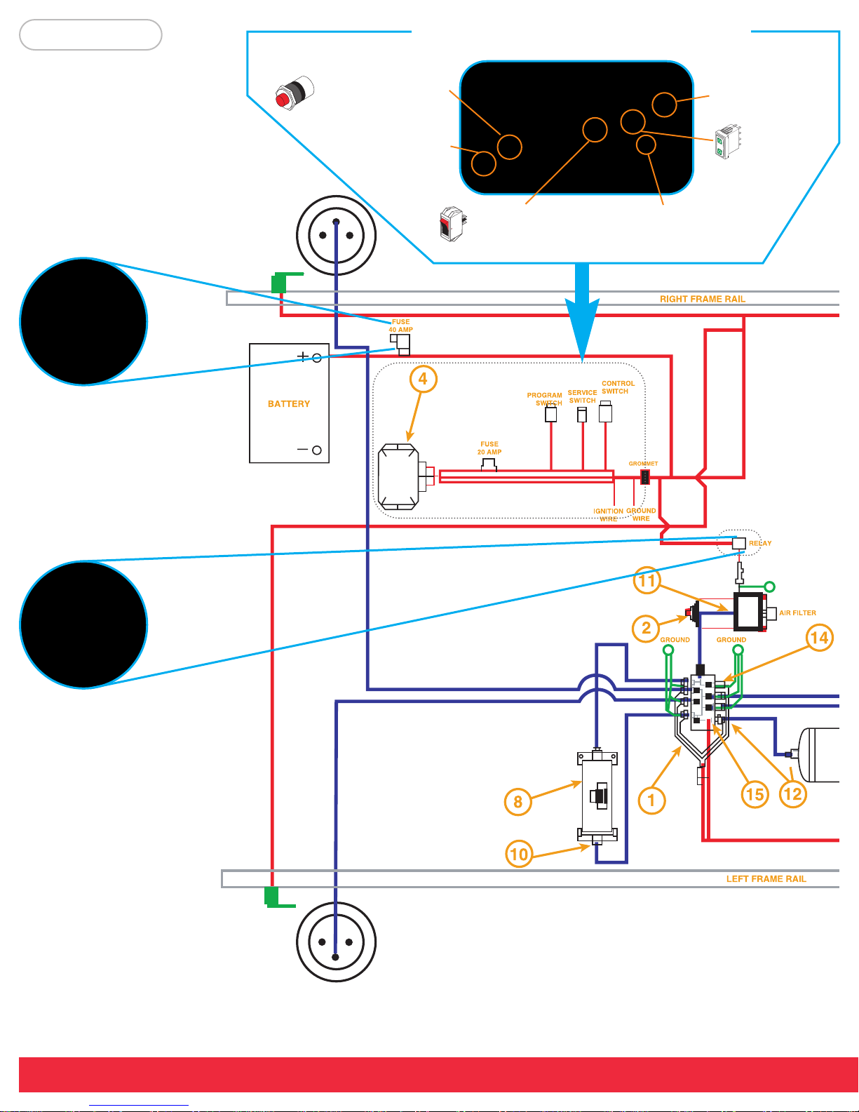
Battery Connection
Connections to be made with
vehicle interior
Program button. This is discon-
nected after programming and
replaced with the Park Wire.
Connector to ECU, to be mounted
inside the vehicle.
Service Switch to be used
to turn the system on and
off.
Ignition wire and ground wire.
Ignition wire should be connected
to a source less than 1/2 amp.
Grommet to be used if needed
in the firewall.
Height Control
Switch
Compressor Relay
To be mounted inside engine bay.
Figure 1

1
IntelliRide™
Full System Schematic
DET DESCRIPTION
1FULL SYSTEM VALVE ASSEMBLY
2AIR COMPRESSOR
3AIR TANK - 3 GALLON
4ELECTRIC CONTROL UNIT (ECU)
5HEIGHT SENSORS
61/4 TUBING 18ft.
7WIRE HARNESS FULL SYSTEM
8AIR DRYER - SYSTEMS
9BRACKET - HEIGHT SENSOR
10 3/8 NPT FITTING, 1/4 TUBE
11 1/8 NPT FITTING, 1/4 TUBE
12 1/4 NPT FITTING, 1/4 TUBE
13 1/4 NPT PLUG
14 1/4 NPT SILENCER
15 PRESSURE SENSOR
3/16” Flat Washer (16) 10-32 Nylon Lock Nut (13)
10-32 x 1” Machine Screw (11)
Miscellaneous Mounting Hardware
This manual suits for next models
2
Table of contents
Other Firestone Automobile Accessories manuals

Popular Automobile Accessories manuals by other brands


ULTIMATE SPEED
ULTIMATE SPEED 279746 Assembly and Safety Advice

SSV Works
SSV Works DF-F65 manual

ULTIMATE SPEED
ULTIMATE SPEED CARBON Assembly and Safety Advice

Witter
Witter F174 Fitting instructions

WeatherTech
WeatherTech No-Drill installation instructions

TAUBENREUTHER
TAUBENREUTHER 1-336050 Installation instruction