Fireye NXD410TS User manual

1
DESCRIPTION
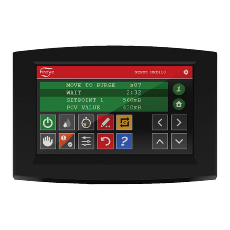
The NXD410TS Touch Screen User Interface provides the means to setup, monitor and display all information
from the PPC4000 and NXF4000 Control and connected accessories. The NXD410TS is a 4.3” widescreen TFT
color touchscreen. The NXD410TS is panel mounted and connects directly to the PPC4000 and NXF4000 using
cable part number 59-561 available by the foot.
Refer to Bulletin PPC-4001 for a complete description of the PPC4000 control system or for NXF4000 See
Bulletin NXF-4001.
SPECIFICATIONS
NXD410TS
Supply Voltage: 24 Vdc (18 to 30 Vdc)
Power
Consumption: 0.60A at 24Vdc (max.)
Temperature Rating: 32°F to 122°F (0°C to +50°C)
Protection Category: Indoors use only, IP40
Unit Dimensions:
Faceplate LxH 129x88 mm
(5.1“)x(3.45“)
Cutout AxB 106.5x73.025 mm
(4.19“)x(2.875“)
allow 1.725” (43.8mm) depth clearance
Interface Method: RS485, 57600 Baud
Shipping Weight: Approx. 0.9 lbs. (0.41 Kg)
NOTE: Proper operation of the NXD410TS Touchscreen displa
y
requires a PPC4000 with an
Engineering code of 9 or greater or a PPC4000 running main firmware revision v3.7 or greater.
Due to limitations of Modbus RTU, only one master can exist on the Modbus interface. The
NXTSD4xx Touchscreen display is considered the master of the bus and the Modbus
system should be configured such that the Touchscreen display is the only device speaking
to the PPC4000(s) on the bus.
NXDTS-4410
December 16, 2019
NX
D
4
10TS
TOUCHSCREEN
INSTALLATION GUIDE
USED WITH PPC4000 and
NXF4000 FUEL AIR RATIO
CONTROLLER

2
Standards and Approvals:
UL File # XAAF.MP1537 (USA)
XAAF7.MP1537 (Canada)
The products have been designed for use in an industrial environment in compliance with the
2014/30/EU EMC Directive, 2014/35/EU LV Directive, and 2011/65/EC RoHS Directive.
The products have been designed in compliance with:
EMC – EN 60950-1:2006
Emissions – EN 55032:2015
Immunity – EN 55035:2017
The installation of these devices into the residential, commercial and light-industrial environments
is allowed only in the case that special measures are taken in order to ensure conformity to EN
61000-6-3.
The products are in compliance with the Restrictions on Certain Hazardous Substances (RoHS)
Directive 2011/65/EC. (RoHS compliant)
In compliance with the above regulations the products are CE marked.
INSTALLATION
The NXD410TS is a panel mounted devices. Use the panel cutout template shown
below. Note: Mounting hardware included. (2X M4X25mm studs, 2X M4 Thumb
nuts)
FIGURE 1. Panel Cutout

3
NXD410TS CONNECTION TO PPC4000/NXF4000
NXD410TS VDC IN TO PPC/NXF4000 Descri
p
tion
VDC IN
p
in 2
(
VDC+
)
P2.1 24 VDC POWER
(
Red
)
VDC IN
p
in 1
(
VDC-
)
P2.6 24 VDC RETURN
(
Black
)
NXD410TS IOIO TO PPC/NXF4000 Descri
p
tion
Tx+ P12.10 Dis
p
la
y
Tx
(y
ellow
)
Tx- P12.9 Dis
p
la
y
T
y
(
Blue
)
Rx+ P12.7 Dis
p
la
y
Ra
(
Oran
g
e
)
Rx- P12.8 Dis
p
la
y
Rb
(
Brown
)
GND Screw CHASSIS Drain wire GND
(
Shield
)
Note: Ethernet, USB B and USB A ports are not active.
Note: All connection colors represent Fireye cable part number 59-561 and is available by the
foot.
Power Ethernet USB B USB A Serial Port
FIGURE 2.

4
DISPLAY CONFIGURATION
The following information outlines button functions of the NXD410TS touch Screen display.
1. Display Configuration Fundamentals.
The NXD410TS display allows the installer or technician to configure/maintain operation of
PPC4000/ NXF4000 controller within the associated burner environment. Please refer to bulletin
PPC-4001 for further control setup information for the PPC4000. Please refer to bulletin NXF-
4001 for further control setup information for the NXF4000.
FIGURE 3. Main Screen Button Definitions
1. Burner on/off button. Green = Burner on, Gray = Burner off
This setting allows the control to turn the burner ON/OFF using the digital input. The operation
of this setting is impacted by the keypad Burner ON/OFF key.
2. Sequence lead/lag control. Green = Lead mode, Gray = Lag mode
This feature allows the user to select a sequencing master (lead boiler) in a sequencing chain.
Sequencing must be configured properly in the sequencing menu in order to select the feature
via the digital input.
3. Reset. For resting a locked out condition.
When active, the digital input allows the user to remotely reset the control during a lockout
event. Note: When using this display with the PPC4000, the reset button will rest the unit with
no limitations. When using this display with the NXF4000, the reset button will be limited to
no more than 5 reset attempts in a 15-minute window. After that 5th reset, the unit can no
longer be reset. To overcome this reset limitation you must recycle the power or insert an SD
card. If an SD card is already inserted, it must be removed and reinserted to reset the reset this
limitation.

5
4. Low Fire. Green = Low Fire Hold, Gray = Normal fire modulation based on real demand.
This setting allows the control to maintain a low fire modulation rate using the digital input.
The operation of this setting is impacted by the keypad Low Fire key.
5. Auto/manual modulation mode
This setting gives the user the ability to place the control in Manual Modulation Mode. Manual
adjustment of the modulation rate can further be done using the keypad or via Modbus. The
operation of this setting is impacted by the keypad AUTO/MAN key.
6. Dual function- Check/run and fault information
This setting gives the user the ability to enable or disable the RUN/CHECK operation via the
digital input. See the BURNER CONTROL SETUP (See Bulletins PPC-4001 or NXF-4001)
section for information on run/check operation. This also allows the user to retrieve Fault
History Display.
7. Commissioning Mode
Go to the Commissioning or Adjust Ratio Mode. LED illuminates when C-MODE is enabled
(after passcode enabled). While in Commissioning Mode or Adjust Ratio Mode, hitting C-
Mode is used to correctly terminate Commissioning and Adjust Ratio Mode.
8. Jump to set point adjust menu
This function allows direct access to the set point menu for set-point, Cut In, Cut Out, P-Band
and other Set-point setup parameters.
9. Begin modify/save changes
Modify “Green” enters modify mode. UP/DOWN arrows are used to modify current value.
SAVE “Red” Save/ enters current parameters being entered.
10. Information
Show summary of servos positions, VFD speed, DI activations and other top level data.
11. Home
From anywhere and in any menu or submenu, immediately suspends any modify mode if
enabled and directs user to default or main screen.
12. Navigation up/raise setting
Move up to the previous menu item. When in MODIFY mode, used to increment numerical
value.
13. Navigation down/lower setting
Move down to the next menu item. When in MODIFY mode, used to decrement numerical
value.
14. Navigation Backwards
Move back one menu layer to navigate with in the menu.
15. Navigation Forwards
Move forward one menu layer to navigate with in the menu. This function is also used to
advance within the combustion curve.

6
16. Help
The help menu provides detailed information on the buttons and feature shown on this display.
The main display area will changes color dependent upon mode as the information shown changes. This is in priority
order – e.g. a lockout background color (red) will supersede commissioning mode (yellow):
a. Green – normal
b. Yellow - Adjust ratio/commissioning mode
c. Red – Lockout

7
This page intentionally left blank

8
NOTICE
When Fireye products are combined with equipment manufactured by others and/or integrated
into systems designed or manufactured by others, the Fireye warranty, as stated it its General
Terms and Conditions of Sale, pertains only to the Fireye products and not to any other
equipment or to the combined system or its overall performance.
WARRANTIES
FIREYE guarantees for one year from the date of installation or 18 months from date of
manufacture of its products to replace, or, at its option, to repair any product or part thereof
(except lamps, electronic tubes and photocells) which is found defective in material or
workmanship or which otherwise fails to conform to the description of the product on the face of
its sales order. THE FOREGOING IS IN LIEU OF ALL OTHER WARRANTIES AND
FIREYE MAKES NO WARRANTY OF MERCHANTABILITY OR ANY OTHER
WARRANTY, EXPRESS OR IMPLIED. Except as specifically stated in these general terms
and conditions of sale, remedies with respect to any product or part number manufactured or sold
by Fireye shall be limited exclusively to the right to replacement or repair as above provided. In
no event shall Fireye be liable for consequential or special damages of any nature that may arise
in connection with such product or part.
WARNING: THE INAPPROPRIATE SELECTION OR APPLICATION OF A SYSTEM
SETTING COULD RESULT IN AN UNSAFE CONDITION HAZARDOUS TO LIFE AND
PROPERTY. Selection of the proper settings for a particular application should be made by a
competent professional, such as a Boiler/Burner technician licensed by a state or government
agency, engineering personnel of the burner, boiler or furnace manufacturer (OEM) or in the
performance of duties based on the information from the OEM.
The equipment described in this manual is capable of causing property damage, severe injury,
or death. It is the responsibility of the owner or user to ensure that the equipment described is
installed, operated and commissioned in compliance with the requirements of all national and
local codes.
FIREYE®
3 Manchester Road
Derry, New Hampshire 03038 USA
www.fireye.com
NXDTS-4410
December 16, 2019
Other manuals for NXD410TS
2
Table of contents
Other Fireye Touchscreen manuals
