Firgelli FA-TVL-180 Series User manual
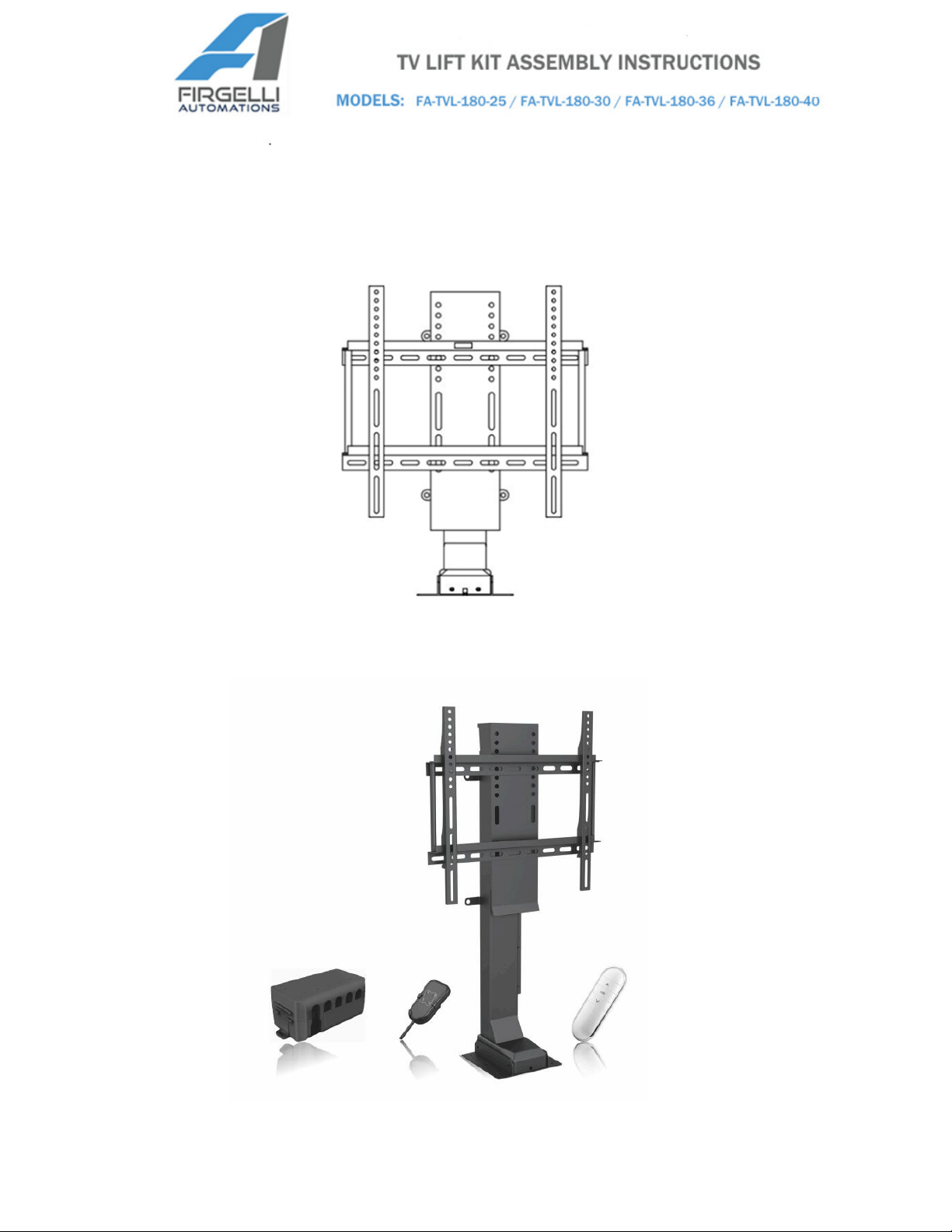
The FA-TVL-180 Series Pop-Up TV Lift
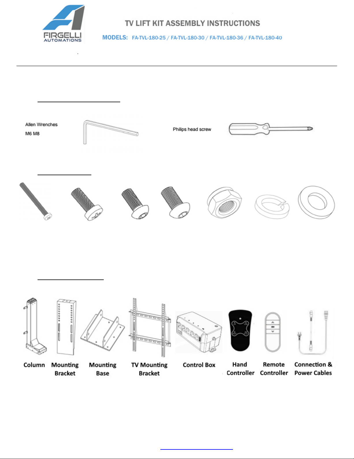
Please take time to identify all the parts and hardware prior to assembly. Lay out all the
components on a padded /carpeted area to avoid damage.
TOOLS REQUIRED
HARDWARE
2 Screws M5x50 4 Screws 8 Hex Bolts 4 Hex Bolts 4 Nuts 8 Spring Washers 8 Washers
M5x50 M6x16 M6x14 M8x16 M8 M6 M6
COMPONENTS
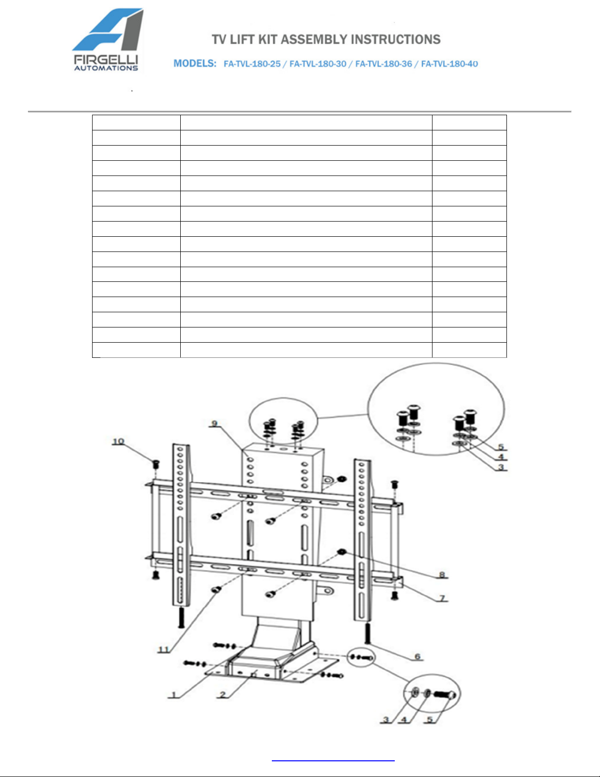
NO.
TYPE
QTY
1 Mounting Base 1
2 Column 1
3 Washers M6 8
4 Spring Washers M6 8
5 Hex Bolts M6x14 8
6 Screws M5x50 2
7 TV Mounting Bracket 1
8 Nuts M8 4
9 Mounting Bracket 1
10 Screws M6x16 4
11 Hex Bolts M8x16 4
12 Connection and Power Cable 1
13 Remote 1
14 Handset 1
15 Control Box 1
ASSEMBLY AND INSTALLATION
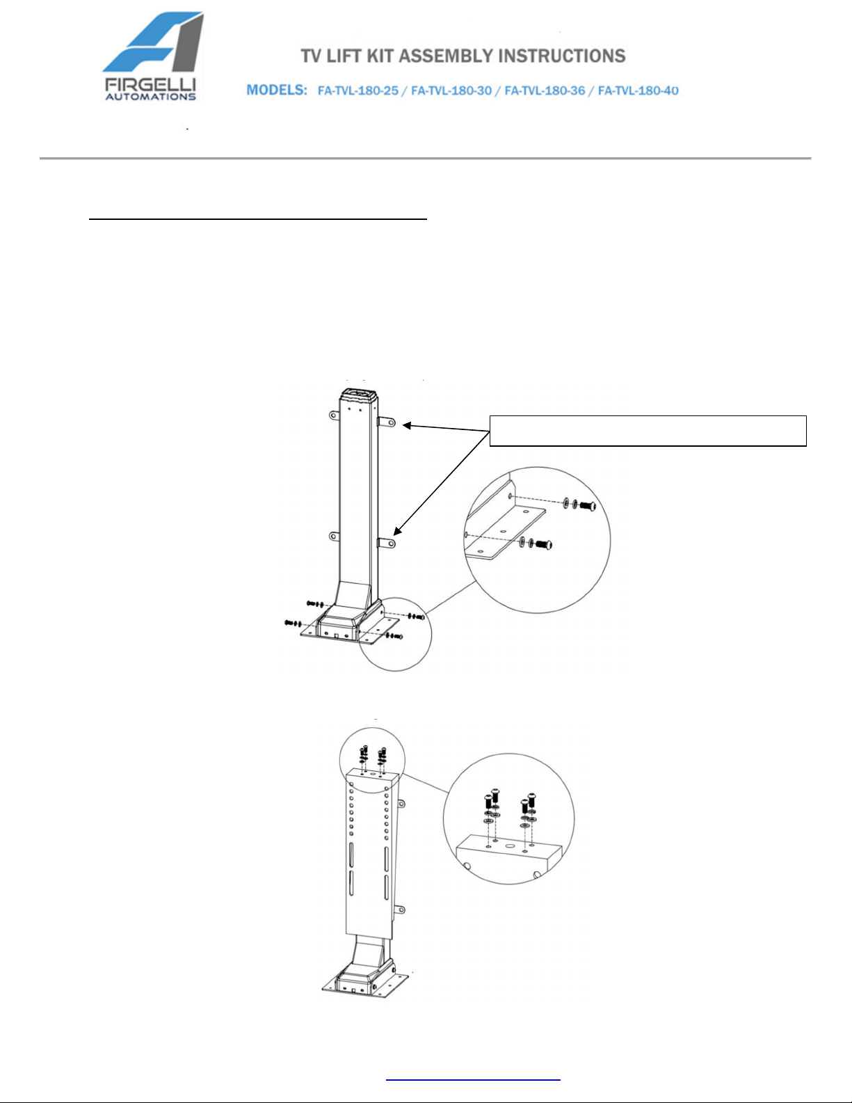
When installing the TV Lift, you have two mounting options. You can use the base plate and mount it to
the bottom of a cabinet or floor. The second option is to use the 4 back mounting tabs to mount it
against a wall or the back of a cabinet.
1. First mount the base plate to the floor or ceiling if used upside down. Then use 4 Hex Bolts
M6x14, each with a Spring Washer and Washer, to attach the Mounting Base to the bottom of
the Column. Tighten the 4 Bolts (2 per side).
2. Use 4 Hex Bolts M6x14, each with a Spring Washer and Washer, to attach the Mounting
Bracket to the top of the Column. Tighten the 4 Bolts.
Optional tabs for wall mounting

3. Use 4 Screws M6x16, to assemble the TV Mounting Bracket as follows.
The long arms will attach to the back of your flat screen TV. All TV’s come with the same mounting
holes, this bracket is designed to be universal so that it works with all TV’s and gives you flexibility to
position the TV relative to the Lift however you prefer.
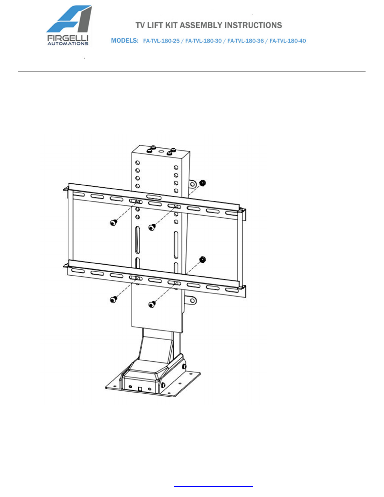
4. Use 4 Hex Bolts M8x16, with 4 Nuts M8, to attach the TV Mounting Bracket to the Mounting
Bracket. Tighten the 4 Bolts. The Mounting Bracket comes with different mounting positions to
allow for different sized TV’s.
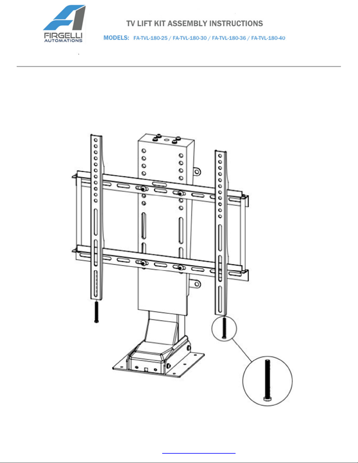
5. Secure the other 2 long arms of the TV Mounting Bracket onto the back of the TV set with 4
screws included with the TV set. Then hang the TV set onto the TV Mounting Bracket as
shown. Use 2M5x50 screws to tighten on the bottom.

6. Connect the hand controller (9 pin plug) with the HS port on the control box. Connect the lift
column (5 pin plug) with the 1st port on control box. Ports No.2-4 are blocked and cannot be
used. Connect the power cable to the control box and plug into power source.

OPERATION
RESET:
The system has to perform a complete RESET in order to operate. The red signal light will flash at
0.5 second intervals indicating a RESET is required.
Press and hold the RESET button on the Hand Controller to lower lift all the way to the bottom. Once
the lift reaches the bottom it will then raise 7mm and the light shuts off indicating the RESET is
complete.
The RESET button must be held and cannot be released during the process. The LED light on the Hand
Controller will flash rapidly, when light turns off, it means the RESET is done.
Notes:
Before RESET procedure is completed; no buttons will function except the RESET button on the hand
controller.
Press and hold RESET button 5 seconds in order to activate the RESET procedure intentionally.
hen the lift is moving, pressing RESET will stop its motion. If RESET is held for at least 5 seconds, the
system will enter the RESET procedure automatically.
STUDY:
Before using the Remote Controller, it is necessary to pair the remote to the receiver:
Press + on the Remote Controller as well as the STUDY button on the Hand Controller
simultaneously and hold. The LED light will flash three times, which indicates studying is complete.
Release buttons when studying process is complete.

After completing the RESET and STUDY processes, the following functions are achievable:
REMOTE CONTROLLER:
Press :
Sustaining Mode: press button once and the lift will extend continuously up; press any button to stop it
or it will stop automatically at the set upper limit spot.
Momentary Mode: press and hold button to raise the lift, release button and the lift stops moving.
Press :
Sustaining Mode: press button once and the lift will retract continuously down; press any button to
stop it or it will automatically stop at the set lower limit spot.
Momentary Mode: press and hold button to lower lift, release button to stop;
COM Button:
Use the COM button to switch between sustaining and momentary modes.
Hold COM button 10 seconds to switch from momentary to sustaining mode and vice versa
When the switch is conducted successfully, the red light will be on and the remote controller will
flash to signal that the change has been saved.
•The setting will be remembered for future remote use.
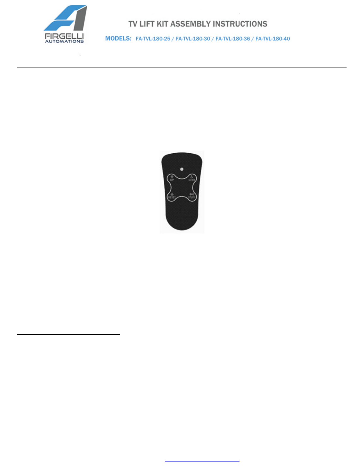
HAND CONTROLLER:
UP button: Press button once, lift rises all the way up to the upper limit position. Press button again to
stop movement before limit has been reached.
Down button: Press button once, lift will lower go all the way down to lower limit position. Press button
again to stop movement before lower limit has been reached.
To set the upper-limit position: Hold the UP and RESET buttons for 3s, when the column reaches the
spot, you want to set as the upper limit position release the buttons.
To set the lower-limit position: Hold the DOWN and RESET buttons for 3s, when the column reaches
the spot, you want to set as the lower limit position release the buttons.
•The system will remember the upper and lower limit positions you have set for future use.
OTHER INFORMATION
•If the column is operated continuously for 3 minutes, it will enter a working protection mode. All
buttons will be disabled during the process. It will return to normal operation after 16 minutes. When
the system enters into working protection mode the indicator light will flash once every 3 seconds.
•If the lift stops working for any other reason, perform RESET procedure

Specifications:
Model FA-TVL-180-25 FA-TVL-180-30 FA-TVL-180-36 FA-TVL-180-40
Stroke 25.5” 29” 35” 39”
Retracted Length 22.4” 25.5” 29.6” 31.89”
Extended Length 48” 54.5” 64.6” 70.89”
TV Sizes 25” – 60”
Input Voltage 110 VAC
Force 135 lbs.
Lifting Speed 0.87”/second (with load)
Duty Cycle 10%, max 2 min. continuous use
Operating
Temperature +5°C - +40°C
Overload
Protection Built-In
Material Powder Coated Steel
Additional Feature Adjustable Height
Thank you for purchasing our TV Lift.
Other manuals for FA-TVL-180 Series
1
This manual suits for next models
4
Table of contents
Other Firgelli TV Mount manuals


Popular TV Mount manuals by other brands


Philips
Philips SQM5222/27 Specifications

AmazonBasics
AmazonBasics B07QDZNDVL manual

EAL
EAL EUFAB 17478 manual

Hama
Hama 00049519 operating instructions

Sanus Systems
Sanus Systems TELEVISION TURNTABLES TV32 Assembly instructions

PEERLESS
PEERLESS PARAMOUNT PF640 and assembly Installation and assembly manual