Firmtec PNP12 User manual

To increase stability the extra bank option may be enabled which by default is
disabled. For most vehicles the additional required processor resources will not
negatively affect overall performance. If the shift light appears to randomly
respond to various engine speeds the DSP sensitivity may be increased slightly.
If the gap between the LEDs is noticeably uneven or inconsistent the DSP
sensitivity may be slightly decreased.
7.1 Fault Finding
Table 4. Fault Finding
We hope you enjoy using this product as much as we enjoyed developing it!
Issue Problem Solution
DSP Mode
No power Blown fuse Check fuse in cigar lighter plug and vehicle
All LEDs flash on startup Stuck Switch Release switch
No response (DSP mode) Sensitivity Reduce Config Parameter 10 (default 7)
Poor response Sensitivity Reduce Config Parameter 10 (default 7)
Flicker throughout range Sensitivity Increase Config Parameter 10 (default 7)
Flicker throughout range Sensitivity Switch on extra RAM bank Config Param 13
Response at RPM/3 Third Harmonic Switch on Third Harmonic Test Config Param 12
Response at RPM/3 Third Harmonic Increase Config Parameter 10 (default 7)
Tacho Mode
No power Blown fuse Check fuses and wiring
All LEDs flash on startup Stuck Switch Release switch
Flicker throughout range Input Filter Increase config param 6 (start @ 0, inc by 1)
No response at high revs Input Filter Increase config param 6 (by 1, down to 0)
Flicker between LEDs Hysteresis Increase hysteresis filter config param 5
Wrong set point No of Cylinders Run Auto Setup
PNP12
4 LED Plug and Play
Sequential Shift Light
Operation Manual
www.firmtec.co.uk
Developed and Manufactured by
Advent Controls Ltd, Liverpool, UK
Made in UK

Exclusion List
If shift point setting Method 1 or calibration repeatedly fails you may need to set
up an exclusion list. This stops sources of electrical noise from equipment other
than the alternator (such as HID lighting, ECUs, fans etc…) being analysed. In
calibration mode this is done by clicking the SET switch with the engine at idle
and the equipment switched on. During the test the display will count down
from 9 to 0. During this time the user may also rev the engine to exclude certain
engine speeds from analysis. Contact support@firmtec.co.uk for further details.
A system reset clears the exclusion list.
5.2 Auto Setup
Auto Setup is used with the 3-wire Tacho Mode to set the number of engine
cylinders. If the shift light is connected to a coil LT wire, then it can be difficult to
determine how many cylinders the coil will fire for. Auto Setup will measure the
time between pulses at a known engine speed and determine this
automatically. It can tolerate some inaccuracy in the rev-counter which does
not affect the overall accuracy of the shift light.
To utilise Auto Setup, enter Calibration Mode (L2 flashing on power up) and
hold the engine at 3000RPM. Press and hold the SET switch (L3 will light as per
the DSP calibration). When the engine speed is stable at around 3000RPM
release the SET switch. The shift light will now calculate the number of engine
cylinders. If successful L1 will be seen flashing alternate with the DSP calibration
result LED and the shift light will return to Tacho Mode (L3 flashing on power up).
If L2 flashes then the setup could not be determined on this occasion. If neither
L1 nor L2 was seen to be flashing then no TACH connection was detected
during the test (check wiring). Do not use Tacho Mode WS with Auto Setup.
6.1 DSP Optimisation
By default, in DSP mode, the Firmtec Sequential Shift Light is optimised for rapid
response at high engine speeds. On engines with high angular acceleration
(the rate at which the revs rise) the shift light may respond poorly or not at all
(particularly at low engine speeds) if additional processor resources are
required by the third harmonic testing, extra memory banks and the 3us
sampling rate (controlled by range cross value).
To increase response rates the user may disable the extra memory bank and
third harmonic test. Changing the range cross value is not recommended.
Disabling the 3rd harmonic test may cause the shift light to respond to engine
speeds 1/3 that of the set speed (e.g. 2000rpm when set to 6000rpm). This can
be ‘tuned out’ by gradually increasing the DSP Sensitivity.
EMC/EMI Compliance Statement: CE Mark Declaration of Conformance
This product conforms to the following specifications:
EMC: EN55022
Safety: EN60950
Immunity: EN55024
This product complies with European Directive 1995/5/EC.
Manufacturer's Disclaimer Statement
The information in this document is subject to change without notice and does not represent a commitment on the part of the v endor.
No warranty or representation, either expressed or implied, is made with respect to the quality, accuracy or fitness for any particular
purpose of this document. The manufacturer reserves the right to make changes to the content of this document and/or the products
associated with it at any time without obligation to notify any person or organisation of such changes. In no event will the manufacturer
be liable for direct, indirect, special, incidental or consequential damages arising out of the use or inability to use this product or
documentation, even if advised of the possibility of such damages. This document contains materials protected by copyright. All rights
are reserved. No part of this manual may be reproduced or transmitted in any form, by any means or for any purpose without expressed
written consent of its authors. Product names appearing in this document are mentioned for identification purchases only. All trademarks,
product names or brand names appearing in this document are registered property of their respective owners.
Contents
1.1 Introduction 1
2.1 Installation 2
3.1 Setup and Usage 4
3.2 Setting the Shift Point 5
3.3 Switching off the Display 7
4.1 Configuration Parameters 8
5.1 Calibration 12
5.2 Auto Setup 14
6.1 DSP Optimisation 14
7.1 Fault Finding 15
1.1 Introduction
The Firmtec Sequential Shift Light was designed primarily for motorsport
applications allowing for no compromise in performance and reliability. Giving
the driver a clear visual indication of the approaching rev-limit allows for perfectly
timed gear changes resulting in maximum performance. Performance gained by
optimising the gear change alone yields valuable ‘tenths’ per lap adding up to
many seconds per race and that’s not including the gains from allowing the driver
full concentration on the road and not the rev-counter. The Firmtec Sequential
Shift Light has 3 high brightness Light Emitting Diodes (LEDs) which light sequentially
over the user-defined rev band preceding the shift point. This gives the driver the
chance to anticipate the shift point, without having to concentrate on a rev-
counter, and the final ultra bright shift light confirms the precise moment at which
the next gear is required.

Pulley Ratio = PC / PA
Example
If the Crank and Alternator Pulleys measure 13cm and 5cm respectively, the
Pulley Ratio is equal to:
13.0/5.0 = 2.60
This is entered using the digital set function in a similar way to entering a shift point
engine speed. To enter this ratio, in calibration mode, the SET switch is double
clicked to enter the digital set function. 2.60 would be entered as 2, 6, 0 (as if
setting the engine speed to 2600RPM). The shift light will automatically exit
calibration mode and return to DSP mode on completion.
Number of Claw Poles
You can often see the number of claw poles within the alternator through the
outer casing (see Figure 3). This is the number entered using configuration
parameter option 8. Most vehicles have a 6 pole alternator. Note this value must
be entered outside of Calibration Mode as only pulley ratios can be entered
whilst in this mode.
P
A
P
C
Crank
Pulley
Alternator
Pulley
The latest version of the Firmtec Sequential Shift Light uses sophisticated Digital
Signal Processing (DSP) techniques to analyse the vehicle electrical system. From
this data the shift light is able to calculate vehicle engine speed with only a simple
two-wire connection to the vehicle wiring loom. Connection through the cigar
lighter socket is sufficient on most vehicles making the Firmtec Sequential Shift
Light a truly plug and play device.
The Firmtec Sequential Shift Light has two operating modes; DSP and Tacho. In
DSP mode the Firmtec Sequential Shift Light performs a spectrum analysis on the
vehicle electrical system to derive engine speed and requires a simple two
wire/cigar lighter connection. In Tacho mode the Firmtec Sequential Shift Light is
connected like a conventional shift light to the vehicle tachometer drive or
ignition coil. In this mode the user has more precise control over the first 3 LEDs.
Quiescent Current (Standby): <1mA
Maximum Current (4 LED): 85mA
Minimum Operating Voltage: 9V
Maximum Operating Voltage: 16V
Processor: 32MHz RISC MCU (8MIPS)
DSP Technique: Fast Fourier Transform (up to 60kHz)
Accuracy: Better than 10rpm*
Maximum Engine Speed: up to 18000rpm*
*tacho mode only
2.1 Installation
2-wire Plug and Play
The Firmtec Sequential Shift Light requires only a simple a two-wire connection to
the vehicle. It is supplied with a standard 12v accessories/cigar lighter connector
for easy connection to the vehicle and is ready to be used as soon as it is
plugged in.
Alternative Tachometer Connection
For more precise control of the shift light the standard plug can be removed
exposing three wires (+/GND/TACH) for connection to the vehicle tachometer
drive or ignition coil. It is recommended that the device be connected to a
‘switched’ supply which operates on the ignition switch – especially when fitted to
vehicles which are not in regular use. It is essential that the positive supply is not
connected directly to the positive side of the ignition coil as this terminal
experiences high voltage spikes which could damage the device and give
erratic operation.
‘Claw Poles’ – This
alternator has 6 pairs

The signal wire, coloured blue, should be connected to the switched Low Tension
(LT) connection of the ignition coil (typically indicated with a (-) sign). There is
normally a connection to this terminal found on the vehicle dashboard wiring
loom. If this is not the case the signal wire will need to be extended and
connected directly to the coil. On distributor-less ignition systems this wire can be
connected to any one of the switched LT connectors. Typically on distributor-less
ignition systems there will be a large diameter positive supply wire with two slightly
smaller diameter switched wires. The blue wire should be connected to either
one of these.
Alternatively the blue wire can be connected to the tachometer drive output.
This is essential on Capacitive Discharge Ignition (CDI) systems.
It is recommended that ‘snap-lock’ connectors are used to connect the cable to
the vehicle wiring loom. Alternatively soldering directly to the existing cabling is
also acceptable. Any poor connections will result in erratic operation of the unit
and may cause flickering of the LEDs. Please refer to Figure 1 and Figure 2 for
schematic diagrams.
Red: 12V + VE (e.g. Battery (+) terminal)
Green: 0V Earth (e.g. Vehicle Chassis or Battery (–) terminal)
Blue: Signal Wire. Connect Directly to Coil LT (-)/Tach terminal
Figure 1. Conventional Ignition Wiring Diagram
Figure 2. Wasted Spark Distributor-less Ignition Wiring Diagram
5.1 Calibration
For the digital set functions to work accurately the unit must first be calibrated.
DSP Mode
The primary source of electrical noise in the vehicle electrical system is caused by
the alternator. The alternator is a 3-phase alternating current generator which is
rectified and regulated to DC at 14.4v. As it is an alternating current device it
produces energy at a certain frequency proportional to engine speed and the
number of ‘claw poles’ within it. The alternator is typically driven faster than the
engine and the ratio of alternator speed to engine speed is equal to the ratio of
the large crankshaft drive pulley to the smaller alternator drive pulley.
There are two ways of calibrating the shift light for DSP Mode. The unit can
measure the alternator output frequency at a specific engine speed (3000RPM) or
the user can specify the pulley ratio and number of claw poles (typically 6). This
information is available on the Firmtec website for certain vehicles or can be
physically measured on the vehicle.
Engine Speed Sampling
The easiest way to calibrate the shift light is to measure the alternator frequency
at a known engine speed. To do this calibration mode must be selected (L2
flashing on power up). To calibrate the shift light, press and hold the SET button.
LED L3 will display after 2 seconds. When the engine is at precisely 3000RPM,
release the SET button. The recorded data is now analysed (this may take up to 2
seconds) and if the operation is successful the red LED L4 will flash to confirm this.
If the blue LED L3 flashes this indicates that the operation was not successful and
should be tried again. If repeated attempts at calibration fail you may need to
set up an exclusion list (see Exclusion List for details).
Entering Pulley Ratio
In calibration mode (L2 flashing on power up), the digital set function sets the
pulley ratio only. No other configuration options are available in this mode.

3.1 Setup and Usage
L1 L2 L3 L4
L1 (Blue) L2 (Blue) L3 (Blue) L4 (Red)
DSP Mode Calibration Mode Tacho Mode Tacho Mode WS
Table 1: Ignition type setup
When the unit is first powered on the current setup is indicated by the flashing
LEDs as shown in Table 1.
The operating mode is changed by pressing the set button once whilst the
current mode is being displayed (LED flashing at power-up).
DSP Mode
This mode makes use of the 2-wire plug and play setup and is the default mode
for the shift light. The shift point can be set using Method 1 (Half Engine Speed)
or Method 2 (Digital Set). However, for digital set to be accurate in DSP mode
the shift light must first be calibrated using Calibration Mode.
Calibration Mode
This mode is selected to calibrate the shift light for DSP mode or to make use of
the Auto Setup function in Tacho Mode. For further detail see Calibration/Auto
Setup
Tacho Mode
This mode is used to make use of the three wire setup. It allows for more
accurate control of L1, L2 and L3 and does not require calibration. However, it
is important to first select the correct engine type (number of cylinders – see
Configuration Parameters) or to run the Auto Setup function.
Tacho Mode WS
Range Crossover
The Firmtec Sequential Shift Light has two DSP operating modes optimised for low
and high engine speeds. This value controls the crossover set point which is
typically around 4000RPM by default and is optimum for most engines.
Third Harmonic Test
Setting this option to 1 enables the third harmonic test and setting it to zero
disables the test. A harmonic is an integer multiple of a signal such that it’s
measured frequency would be n x fq (n is the harmonic, fq is the fundamental
frequency). A pure, noise free signal would provide considerable energy for a
circuit tuned to it’s third harmonic and appears as a peak on a spectrum analysis
plot. The third harmonic test is used to determine whether the energy at this
frequency is caused by a fundamental or a harmonic however this analysis adds
to the workload of the processor. See optimisation for more details.
Extra Sample Bank
Setting this option to 1 enables the additional memory bank to be used and
setting to zero disables the additional memory bank. The voltage of the electrical
system of the vehicle is rapidly sampled and stored every 3μs (microseconds) and
analysed thereafter. The extra bank option enables an additional memory
allocation for storing data; however this creates additional workload for the
processor. See optimisation for more details.

light will illuminate at the set engine speed whereas it will extinguish at a slightly
lower engine speed – the difference being controlled by the hysteresis value.
Please contact [email protected]o.uk for further details. A high hysteresis value
may be required on some ‘V’ engines due to the offset in timing between
cylinders.
Filter Coefficient (Option 6)
This value can be adjusted to change the latency of the input and should be
minimised to ensure adequate response to high engine speeds. If the shift light
regularly flickers at engine speeds below that of the set point this value may be
increased (try starting at 1, incrementing by 1). If the shift light does not
respond to high engine speeds this value may be reduced down to 0. Please
contact support@firmtec.co.uk for further details.
DSP Mode LED Gap (Option 7)
This value sets the relative gap between LEDs in DSP mode when using the
digital set function. Please note the RPM gap is larger at higher engine speeds
than at lower engine speeds. A value of 0 may correspond to approximately a
30RPM gap at 3000RPM whereas this would be approximately 60RPM at
6000RPM.
Number of Poles (Option 8)
This value corresponds to the number of ‘claw poles’ in the vehicle alternator.
Typically an automotive alternator has 6 poles, which is the default value. See
Calibration Mode for further details.
Operation Mode (Option 9)
This is an alternative method for setting the operating mode of the shift light.
0 DSP Mode
1 Calibration Mode
2 Tacho Mode
3 Tacho Mode WS
DSP Mode Sensitivity
This option sets the Global Fourier Energy Limit for the device. The energy level
of each frequency in the spectrum is analysed and this value sets the minimum
energy level a signal must reach to be considered valid. See Optimisation for
information on how to use this control.
This mode is intended for use when connected to a ‘Wasted Spark’ type coil
pack. It is included to remain compatible with legacy devices but is not
recommended for general use. If the vehicle engine is a 4-cylinder WS type and
the TACH connection is connected to a coil then this mode can be used with the
default settings for an instant setup.
3.2 Setting the Shift Point
There are two methods of setting the shift point engine speed. Generally Method
1 is used as an approximate setting (and to set the rev-band if required) and
Method 2 is used for accurately setting the shift point.
Method 1: Half Engine Speed
Method 1 can be used in both DSP and Tacho modes. With the engine running,
press and hold the SET button (the LED will light after 2 seconds to show set mode
has been entered). Raise the engine speed to half that of the shift point and
allow the engine speed to settle. Once the engine speed is stable the SET button
is released and the desired shift point engine speed is set. It should be noted that
at engine speeds above 1250rpm (Tacho mode only) the red LED (L4) will light
indicating the minimum engine speed setting (shift point – 2500rpm) has been
reached. If this is not the case check setup and installation.
If setting the shift point has been successful the LED RPM gap is now set. By
pressing the SET button once, the current setting can be changed and is shown on
the LEDs. Once the desired setting is displayed the SET button is held until all LEDs
are extinguished. This stores the new interval setting. This interval setting is also
used when setting the shift point digitally using Method 2.
In DSP mode the exact RPM gap between LEDs is not accurately configurable. L1
gives the minimum gap between LEDs and L4 gives the maximum.
In Tacho mode the gap can be set to 50rpm (L1), 100rpm (L2), 150rpm (L3) or
200rpm (L4). For example, if set to 200rpm the LED prior to the shift point, L3, would
light at 200rpm less than the shift point LED (L4). L2 would light at 200rpm less than
the L3 engine speed and so on. This would give a total rev-band of 600rpm from
the first LED (L1) to the shift point (L4).
Example: Setting the shift point to 6000rpm
Hold engine speed at 3000rpm and press and hold SET. LED L1 will illuminate to
show set mode has been entered and in Tacho mode the red LED L4 will illuminate
to show the minimum engine speed (1250rpm) has been

reached. Release the SET button. The shift point has now been set to 6000rpm.
In Tacho mode to set an interval of 200rpm the SET button should be pressed
repeatedly until the red LED L4 is illuminated. In DSP mode this would give the
maximum RPM gap. The SET button should now be held until all LEDs have
been extinguished. The setup is now complete. The following should now be
observed whilst driving:
5400RPM 5600RPM 5800RPM 6000RPM
Method 2: Digitally Entering a Shift Point
Method two allows the user to accurately define a shift point between 1000
and 9990rpm. This can be done with the engine on or off in DSP or Tacho
modes but not in calibration mode.
Digital set mode is entered by double clicking the SET button which will
illuminate all LEDs.
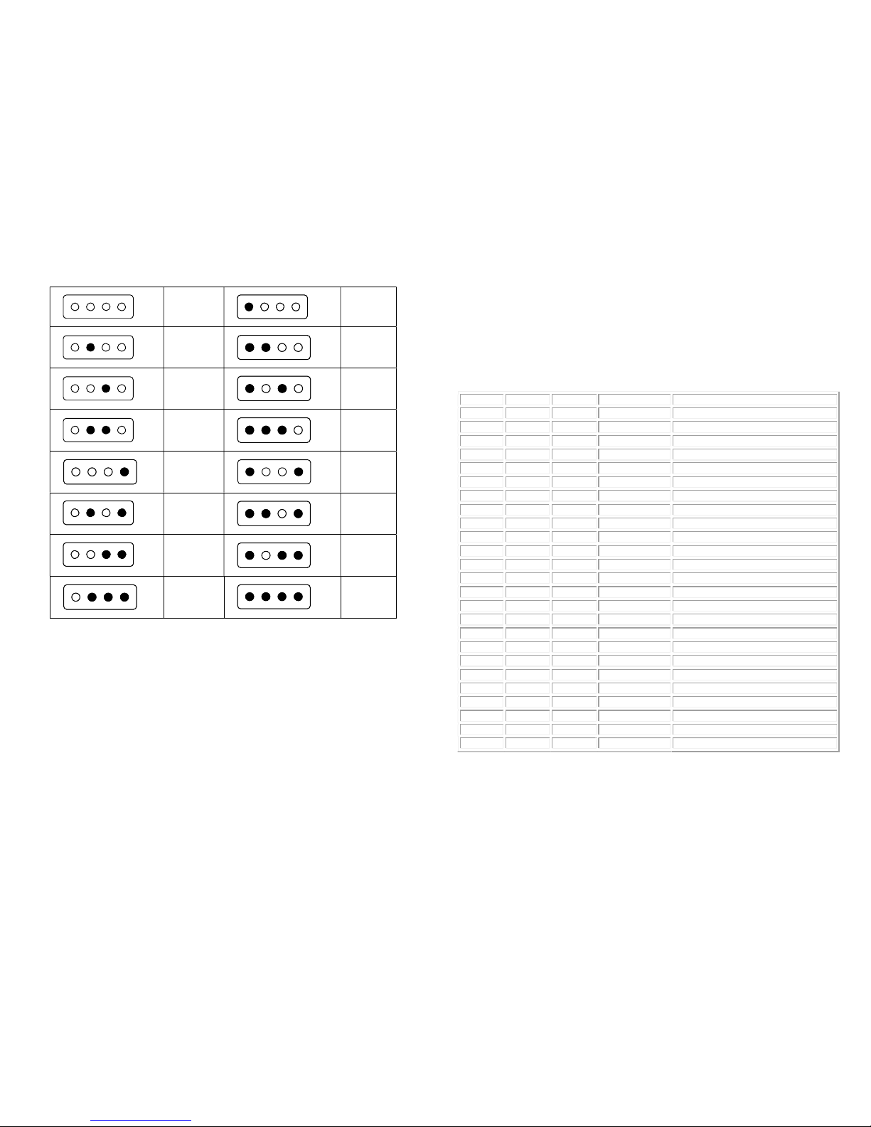
The LEDs will then display a binary value starting at 0 (all off) and will count up to
nine and back to zero, incrementing by 1 every second. Table 2 shows the
binary to decimal conversion however it is not necessary to know or recall this
information as the user can simply count from zero to the desired number value
each time the display changes.
The thousands digit is entered first followed by hundred and tens. To select a
digit the SET button is pressed when the corresponding value is displayed on the
LEDs.
For example, in DSP or Tacho Mode, double click the set button to enter digital
set mode. After the LEDs have extinguished, the display will start incrementing
from zero (all off) to nine. To set the shift point engine speed to 6250rpm count
up from zero (all off) to 6 (off, on, on, off) and click SET to select the thousands
digit. The display will be held for two seconds to confirm the selected digit.
After this the display will continue counting so that the hundreds digit can be
selected. If the desired digit is missed the display will roll-over back to zero and
can be selected the next time it is displayed. When the number ‘2’ is displayed
(off, on, off, off) the button is clicked and this will be shown on the display for 2
seconds. Finally the tens digit can be selected in the same manner. The shift
point is then stored and normal operation is resumed.
Please note holding the switch during initial power up will result in the ‘stuck
switch’ error being displayed.
Default values are as follows:
Engine type: 4-cyl
LED Gaps: 100RPM
Hysteresis Value: 4
Filter Coefficient: 2
DSP LED Gap: 1
Alternator Poles: 6
Operating Mode: 0
DSP Sensitivity: 7
Range Cross: 4
3rd Harmonic Test: On
Extra Sample Bank: Off
Tacho Engine Speed: ~2500RPM
DSP Engine Speed: ~3000RPM (2.60 Pulley Ratio)
LED Gaps (Tacho Mode Only) (Option 1-3)
Individual LED rev differences can be set using this option. The minimum value of
zero corresponds to 50RPM and increases by multiples of 50 RPM with the value
entered (max. 750RPM).
Engine Type/Number of Cylinders (Option 4)
This option is used to set the number of engine cylinders and is used in Tacho
mode to calculate the shift point and LED gaps.
If the TACH connection is made to the ECU tachometer output then this value is
typically set to the number of cylinders of the engine.
If the TACH connection is connected directly to an ignition coil then this value is
the number of cylinders that the coil is used for. For example, with a conventional
4-cylinder, single coil, contact breaker points setup, the coil supplies all 4 cylinders.
In this case the Number of Cylinders is set to 4. In a modern engine which makes
use of a wasted spark type coil pack each coil typically supplies just 2 cylinders.
Hence in this case the Number of Cylinders would be set to 2.
If the user is having trouble setting up this option then the Auto Setup function
should be used in calibration mode to determine this value.
Hysteresis Value (Option 5)
Hysteresis is an engineering term used to describe the ‘one-wayness’ of a system.
There is a small amount of hysteresis programmed in to the shift light to account for
minor variations in the timing of the ignition system. The shift
Zero
One
(Red)
Two
Three
Four
Five
Six
Seven
Eight
Nine
Ten
Eleven
Twelve
Thirteen
Fourteen
Fifteen
Table 2: Binary Code
3.3 Switching off the Display
To switch off the Firmtec Sequential Shift Light the SET button is given one short
press with the engine running. The red shift light will be seen to flash 3 times
indicating that the unit is entering standby mode. By pressing the SET button one
more time the unit will return to normal operation, indicated by the Blue L3 LED
flashing 3 times.
4.1 Configuration Parameters
The Firmtec Sequential Shift Light features an in-built configuration menu for
advanced options. The shift light can be operated fully without accessing this
menu which is provided for extra flexibility (firmware v4.06 or greater).
The menu is accessed using the digital set mode by setting the ‘thousands’ digit
to zero (0). For example, to change the engine type to 6-cylinder, the value 0, 4,
6 is entered in the digital set mode.
x1000 x100 x10 Range Description
Mode Item V
0 0 0 Reset to Defaults
0 1 0-14 (V+1) x 50 RPM LED3/LED4 Rev Difference
0 2 0-14 (V+1) x 50 RPM LED2/LED3 Rev Difference
0 3 0-14 (V+1) x 50 RPM LED1/LED2 Rev Difference
0 4 0 4 Engine Type: 16cyl
1 1 1-cyl or one coil per plug
2 2 2-cyl (parallel twin)
3 3 3-cyl
4 4 4-cyl (default 4)
5 5 5-cyl
6 6 6-cyl
7 10 10-cyl
8 8 8-cyl
9 12 12-cyl
0 5 0-14 (V+1) x 8us Hysteresis Value (default 4)
0 6 0-14 (V+1) x 0.25ms Filter Coefficient (default 2)
0 7 0-7 (see notes) DSP LED Gap (default 1)
0 8 0-14 0 – 14 Pairs Number of Poles (default 6)
0 9 0-3 0 – 3 Operating Mode (default 0)
0 10 0-14 0 – 15 DSP Sensitivity (default 7)
0 11 0-14 0 – 15 Sample Rate Crossover (default 4)
0 12 0-1 0 – 1 3rd Harmonic Test (0 – Off, 1 – On)
0 13 0-1 0 – 1 Extra Sample Bank (0 – Off, 1 – On)
Table 3. Configuration Parameters
System Reset (Option 0)
To reset the Firmtec Sequential Shift Light to factory defaults, using digital set
mode, a value of 0, 0, 0 is entered. This can also be achieved by holding the SET
switch whilst the current setup is being displayed during power up.
Table of contents
Popular Test Equipment manuals by other brands


Com-Power
Com-Power CDN-AF4 manual

Valhalla Scientific
Valhalla Scientific 4314KV Operation manual

Keysight Technologies
Keysight Technologies InfiniiVision MSO-X 4022A Programmer's guide

Sykes-Pickavant
Sykes-Pickavant 02695000 instruction manual

Shimpo Instruments
Shimpo Instruments ST-320BL Operation manual

GE
GE Multilin EPM 7000 quick start guide