Sykes-Pickavant 02695000 User manual

Sykes-Pickavant Ltd, Unit 4 Cannel Road, Burntwood Business Park, Burntwood, Staordshire, WS7 3FU. United Kingdom
Tel: +44 (0) 1543 679900 Fax: +44 (0) 1543 679901
e-mail: sales@sykes-pickavant.com www.sykes-pickavant.com
02695000
Pre-Inspecon Headlight Beam Tester
INSTRUCTION MANUAL
Specialist Tool Solutions

2
INDEX
TAKING DELIVERY OF THE DEVICE .....................................................3
INTRODUCTION.......................................................................................3
TECHNICAL DATA ...................................................................................3
SYMBOLS USED IN THE MANUAL.........................................................4
PREPARATION OF THE DEVICE............................................................5
HANDLING THE PACKAGED DEVICE..................................................5
HOW TO UNPACK THE DEVICE..........................................................5
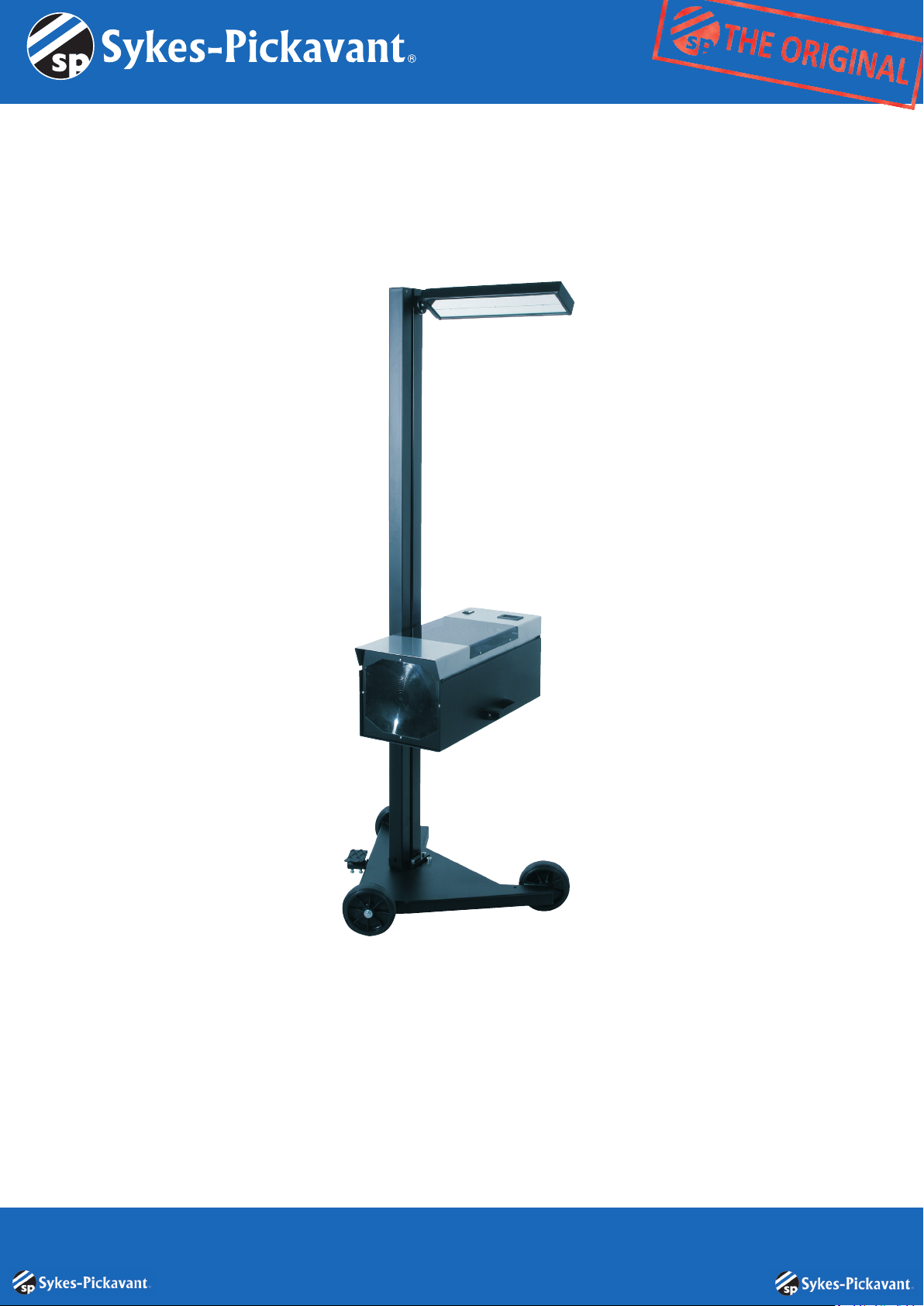
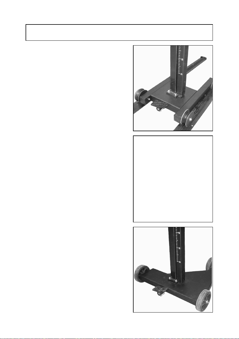
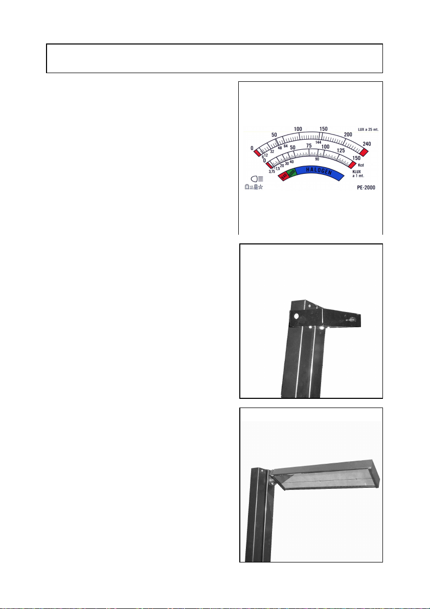
DESCRIPTION OF THE DEVICE..............................................................6
GENERAL SAFETY PRECAUTIONS.......................................................9
PREPARATION.......................................................................................10
ASSEMBLING THE MIRROR VISOR ..................................................10
PREPARATION OF THE VEHICLE .....................................................10
WORK SURFACE................................................................................10
ALIGNMENT OF THE VEHICLE.............................................................11
POSITIONING......................................................................................11
POSITIONING WITH THE HELP OF THE LASER POINTER.............11
ALIGNMENT OF THE VEHICLE.............................................................12
ALIGNMENT WITH THE MIRROR VISOR.........................................12
ADJUSTMENT......................................................................................12
ALIGNMENT WITH THE LASER VISOR............................................13
HEADLIGHT BEAM TESTING ART. 2400 AND 2400/D........................14
ADJUSTMENT......................................................................................14
TESTING THE LOWER BEAM HEADLIGHT.......................................14
TESTING THE UPPER BEAM HEADLIGHT........................................14
HEADLIGHT BEAM TESTING ART. 2400 AND 2400/D........................15
TESTING THE FOGLIGHT BEAM.......................................................15
HEADLIGHT BEAM TESTING ART. 2400/ I ..........................................16
PREPARATION....................................................................................16
ADJUSTMENT......................................................................................16
TESTING THE LOWER BEAM HEADLIGHT.......................................16
HEADLIGHT BEAM TESTING ART. 2400/ I ..........................................17
TESTING THE UPPER BEAM HEADLIGHT........................................17
TESTING THE FOG LIGHT .................................................................17
ADDITIONAL INSTRUCTIONS...............................................................18
REPLACING THE LASER VISOR BATTERIES..................................18
REPLACING THE BATTERIES ART. 2400/D......................................18
REPLACING THE BATTERIES ART. 2400/I .......................................18
ADDITIONAL INSTRUCTIONS...............................................................19
CLEANING AND SERVICING..............................................................19
DEMOLITION AND DISPOSAL............................................................19

3
TAKING DELIVERY OF THE DEVICE
At the moment of taking delivery of the device make sure
that you have received all the material indicated on the
accompanying documentation and that the device has not
suffered any damage during transport. If this should be the
case point out the extent of the damage to the forwarder
and in the meantime contact our customer service
department. Only by promptly following this procedure will it
be possible to receive the missing material and
compensation for damages.
INTRODUCTION
This is a device designed for centering the headlights of
any vehicle or motor-vehicle correctly.
The device must be used exclusivelyfor such purpose.
Even the best machinery can only function properlyand
efficiently if used correctly and kept fully efficient. We
therefore request that you carefully read this instruction
booklet and refer to it every time any difficulties should
arise when using the device. In case of need, we would like
to remind you that our service centres, organised jointly
with our retailers, are always willing to provide any advice
required.
NOTE: for the purposes of updating the device in line with
technological progress and specific production or
installation requirements, the manufacturer may decide
without warning to introduce modifications to it. As a result,
even if the illustrations shown in this manual should differ
slightly from the device in your possession, the safety
features and instructions given in it remain applicable.
TECHNICAL DATA
U/M
width mm 600
length mm 670
height mm 1740
weight kg 30
Power supply voltage art. 2400/D V d.c. 9
Power supply voltage art. 2400/ I V d.c. 12

4
SYMBOLS USED IN THE MANUAL
Warning symbol
Read the section preceded by this symbol carefully, for the safety of th
e operator and the
device.

5
PREPARATION OF THE DEVICE
HANDLING THE PACKAGED DEVICE
The device has its own special box.
Not more than two boxes should be
piled on top of each other.
The weight is 30 kg.
The measurements of the boxes are:
B: 670 mm
L: 590 mm
H: 760 mm
HOW TO UNPACK THE DEVICE
Open the top end of the box and pull
out the device while inclining it
slightly.
Keep the box for possible transport requirements.

6
DESCRIPTION OF THE DEVICE
The headlight beam tester is a device for testing
the headlights of all types of motor vehicles,
vehicles and heavy goods vehicles.
The device can be installed as a fixed station with
“v» wheels and lateral movement on tracks.
The column can rotate, by means of a pin
mounted on precision ball bearings, by about 30°
for alignment with the vehicle and is blocked by a
pedal operated brake.
Using the same base rubber castors can also be
mounted
The headlight beam tester can also be mounted
on a traditional type base which again allows
rotation of the column.

7
DESCRIPTION OF THE DEVICE
The optical box can be adjusted height-wise by
sliding it along silent and precise plastic sliding
blocks balanced by a spring mounted on the
inside of metal sheeting cover containing a
centimetre gauge for exact positioning in relation
to the headlight.
ART. 2400 I
The control monitor has a large, back-lit LCD
display and serial socket RS232, enabling a
number of operations to be carried out rapidly and
guiding the operator in the centering of the
headlight.
Art. 2400/D
The digital display means the luminous intensity
value can be quickly read off.

8
DESCRIPTION OF THE DEVICE
ART. 2400 e 2400/S
The analogical instrument has three scales, two of
which are graduated and one of which is coloured.
The visor facilitating alignment of the device with
the vehicle may function by means of a mirror or
laser.

9
GENERAL SAFETY PRECAUTIONS
The rules shown below should be followed carefully to prevent damage to the operator or the device
Carefully read the safety labels on the device, do not cover them for any reason and replace them
immediately if they should be damaged
The device should only be used by authorised staff trained to use it.
Do not use the device in an explosive environment.
The workplace must be dry and sufficiently aired.
When moving the device watch out for other people and especially children.
Do not bang against shelves or scaffolding where there is a risk of falling objects, you could be injured
or the device damaged.
The storage temperature should be between -5°C and +55°C.
The operating temperature should be between -5°C and 45°C.
Provide an appropriate exhaust fumes extraction system, since the headlights must be tested with the
engine on. Accidental inhalation of carbon monoxide can cause serious injury and even prove fatal.
Contact our area representative to find out which is the best system for your premises.
Avoid leaving the headlight beam tester exposed to sunlight or in the immediate vicinity of sources of
heat such as stoves, radiators etc.
Do not leave the headlight beam tester in the rain or in excessively damp places, the electronic
circuits could be damaged.
If the headlight beam tester is to be left idle for prolonged periods cover it with a special dustsheet
(optional).
The headlight beam tester contains a battery which if handled improperly could cause a risk of fire or
explosion. To prevent such risks do not use sources of heat or naked flames near the battery and in
the event of replacement use another with the same technical characteristics.
If anomalous functioning of the device should be observed request the assistance of the retailer or
send the machine to the nearest servicing centre.
In the event of replacing components, request ORIGINAL spare parts from a concessionaire and/or
Authorised Retailer.
Tampering with any parts of the device will entail lapsing of the guarantee.

10
PREPARATION
ASSEMBLING THE MIRROR VISOR
The mirror visor is calibrated with the respective device
during the testing phase and cannot consequently be
used with other headlight beam testers.
Place the visor beside the plate so that the attachment
holes and external rims coincide; screw on using the
two screws provided.
Do not mount the mirror in a rotated position
(protruding from the joint block) it would be in an
incorrect position.
PREPARATION OF THE VEHICLE
Make sure that the headlights are clean and dry. If the vehicle has its own headlight adjuster inside
the vehicle, position this to “0”. Remove anything which might affect the correct attitude of the
vehicle: mud, snow, ice etc. Straighten up the wheels of the vehicle. Make sure that the vehicle
has no distortion of the body. Check that the tyre pressure is correct. Turn on the engine and
perform the test. In the case of vehicles with pneumatic suspensions turn on the engine five
minutes before starting the test and continue with the engine on.
WARNING!
When working in enclosed areas with the engine on, an extraction system of the noxious fumes
produced is required. Use of a specific exhaust fume extraction system is recommended.
WORK SURFACE
During testing of the headlights the floor surface
should be flat. If this is not possible the headlight beam
tester and the vehicle should, at least, be positioned on
a surface with an even difference in level and in any
case with an incline of not more than 0.5%. The testing
of headlights on surfaces which are not perfectly
regular or flat is not recommended inasmuch as the
adjustment of the same may not be correct.

11
ALIGNMENT OF THE VEHICLE
POSITIONING
Place the headlight beam tester in front of the right
headlight of the car at a distance of approx. 20cm,
measure the height from the ground to the centre of the
headlight and adjust the optical box to the corresponding
height using the graduated scale on the column. Use the
top of the sliding block as an index on the scale.
POSITIONING WITH THE HELP OF THE LASER
POINTER
By turning the wheel on the back of the optical box to the
“0”, position, corresponding to the centre of the lens, a
laser ray will be emitted which will help you to align the
centre of the headlight.
When you set the inclination of the headlight using the
wheel the laser will switch off automatically.
At the end of every test, to prevent the batteries from
going flat, turn the inclination wheel situated at the back of
the optical box to a percentage other than 0% ( e.g. 1%)
WARNING!
Do not look at the laser beam directly during this
operation and make sure that it is not pointing at people
near the workstation.

12
ALIGNMENT OF THE VEHICLE
ALIGNMENT WITH THE MIRROR VISOR
Look for two symmetrical details on the front of the
vehicle (such as the top of the windscreen or the
headlights themselves). Release the column using the
pedal, turn the optical box until the two points of
reference coincide with the black line impressed on the
mirror when looking into the mirror.
OK
NO
ADJUSTMENT
Check that the optical box is level by checking the spirit-
level inside it. If it is not level, loosen the lever in the
picture and adjust the box.

13
ALIGNMENT OF THE VEHICLE
ALIGNMENT WITH THE LASER VISOR
The operator and planner of the workstation should be aware of the risks deriving from laser
beams. The work station should not in any case be in an area of transit, must be clearly identified
and marked off by a yellow line, if possible enclosed by barriers.
Check that there are no people present in the testing area, release the column using the pedal, turn
the visor downwards and turn it on.
Look for two details on the front part of the vehicle, such as the two headlights and turn the optical
box until the two reference points coincide with the line projected by the visor, then block the
column.
WARNING!
Turn off the laser immediately, before continuing any other operations, whether for testing or
adjusting the headlight.
The line laser is in class 3A with a wavelength of 650 nm (nanometres) and a power of 3 mW
(milliwatt) so that even direct observation of the beam with the assistance of amplifying observation
instruments such as binoculars may be dangerous. Accidental exposure is not considered
dangerous inasmuch as since the beam is visible the eyelid reflex does not allow exposure of more
than 0.25 sec.

14
HEADLIGHT BEAM TESTING ART. 2400 AND 2400/D
ADJUSTMENT
At the top of the headlight read off the headlight
inclination given by the manufacturer, e.g. 1.2%, turn
the wheel situated at the back of the optical box
accordingly.
Should no indications be given by the manufacturer,
observe the legal dispositions.
WARNING!
We would like to remind you that the inclination of the
headlights must in any case be in observance of current
law, which states that for lower beam headlights
situated at up to 80cm from the ground the
inclination must be at least 1%.
For upper beam headlights above 80 cm, the
inclination must be at least 1.5%.
TESTING THE LOWER BEAM HEADLIGHT
Check that the position of the projection of the headlight
is aligned with the serigraphed line on the test panel and
if so, press the switch with the lower beam headlight
symbol to read off the value.
TESTING THE UPPER BEAM HEADLIGHT
Check that the position of the projection of the headlight
is aligned with the serigraphed line on the test panel and
if so, press the switch with the upper beam headlight
symbol to read off the value.

15
HEADLIGHT BEAM TESTING ART. 2400 AND 2400/D
TESTING THE FOGLIGHT BEAM
Check that the position of the projection of the foglight is
aligned with the serigraphed line on the test panel and if
so, press the switch with the foglight symbol to read off
the value.

16
HEADLIGHT BEAM TESTING ART. 2400/ I
PREPARATION
Using the UP and DOWN buttons, type in the height
of the headlight from the ground and press ENTER.
WARNING!
If the writing BATTERY FLAT appears when turning
on, connect the battery charger provided to the
socket situated on the back of the optical box and
leave to charge for at least 12 hours; testing can also
be done however with the battery charger connected
and functioning.
ENTER START
ADJUSTMENT
At the top of the headlight read off the headlight
inclination stated bythe manufacturer, e.g. 1.2%,
turn the wheel situated at the back of the optical box
accordingly.
Should no indications be given by the manufacturer,
observe the legal dispositions.
WARNING!
We would like to remind you that the inclination of
the headlights must in any case be in observance of
current law, which states that for lower beam
headlights situated at up to 80cm from the ground
the inclination must be at least 1%.
For upper beam headlights above 80 cm, the
inclination must be at least 1.5%.
TESTING THE LOWER BEAM HEADLIGHT
The display will now read “CHECK RIGHT
HEADLIGHT”, press ENTER.
The wording ”ANB.DX KLX=015,2” (right lower
beam Klux= “read off value ”) will now appear, check
that the position of the projection of the headlight is
aligned with the serigraphed line on the test panel
and if so, press ENTER.

17
HEADLIGHT BEAM TESTING ART. 2400/ I
TESTING THE UPPER BEAM HEADLIGHT
The wording ”ABB.DX KLX=041.5” (right upper
beam Klux= “read off value ”) will now appear on the
display, check the position of the projection of the
headlight on the test panel and press ENTER.
TESTING THE FOG LIGHT
The wording ”FNB.DX KLX=011.4” (right foglight
Klux= “read off value ”) will now appear on the
display, check the position of the projection of the
foglight on the test panel and press ENTER
Now move over to the left-hand side of the vehicle
and repeat the test sequence.
At the end of the procedure the device will forward
the data to the PC station.
WARNING!
In the case of free-standing headlight beam testers
(on rubber castors) after being positioned on the left
headlight, check the alignment once again using the
visor.

18
ADDITIONAL INSTRUCTIONS
REPLACING THE LASER VISOR BATTERIES
Unscrew the two screws on the cover of the laser
visor and replace the 3 1.5V size AA batteries making
sure you put them in the right way up; close the visor
again fixing the cover on using the screws provided.
WARNING!
For longer duration we recommend using alkaline
batteries.
REPLACING THE BATTERIES ART. 2400/D
Should the headlight beam tester device battery need
replacing proceed as follows:
with a crosshead screwdriver unscrew the two self-
tapping screws fixing the battery support to the back
cover of the optical box.
Remove the support and extract the battery, detach
the connector and replace. Reassemble, repeating
the operations described for disassembly in the
reverse order.
WARNING!
For longer duration we recommend using alkaline
batteries.
REPLACING THE BATTERIES ART. 2400/I
To replace the 12Vcc 2Ah lead battery proceed as
follows:
open the optical box, removing the cover, be careful
not to damage the electrical connections.
The battery is attached behind the test panel, to
remove it unscrew the nut with a socket wrench and
unhook the attachment bracket. Remove the battery
and replace with a new one making sure you put it in
the right way up.
Reassemble and check the movement of the test
panel before putting the cover back on.

19
ADDITIONAL INSTRUCTIONS
CLEANING AND SERVICING
The machine does not require special servicing apart from normal cleaning with a damp cloth
(water and spirit or normal detergent).
WARNING!
Do not use nitrogen based solvents
DEMOLITION AND DISPOSAL
The machine is made mainly of steel.
Other parts:
Plastic: some small parts
Cardboard and paper: packaging and documents
Painting of the machine: epoxy, scratch-resistant powder.
For disposal of the machine, observe local council regulations.
Table of contents
Other Sykes-Pickavant Test Equipment manuals