Genie CCTV Rapport mini User manual

P/N : 388087320
PRINTED IN KOREA
FAR
OPEN
TELE
OSD
NEAR
CLOSE WIDE
COM V/
300V 300V~
MAX
V
~~♬
MODE SET
PWR
CHG
Tx
Rx
Rapportmini
Multi Functional CCTV Tester

BEFORE USING RAPPORT mini
SAFETY INFORMATION
PRODUCT INTRODUCTION
PRODUCT SPECIFICATION
Dimensions
LED Indicator
FUNCTIONAL SPECIFICATION
Mode Setup
Video Tester
Colour Bar Generator Mode
Digital Multimeter
Measuring AC & DC Voltage
Measuring Resistance
Continuity Testing
PTZ Controller
SPD(SPEED)
GPST(GO TO PRESET)
SPST(SET PRESET)
FUNC
MENU
DATA
4
5
6
12
14
15
16
17
18
20
22
24
25
25
26
28
29
29
29
30
31
Setup
USER NAME
SLEEP TIME
BEEP
FLASH
SYMBOLS
33
34
34
34
35
36
TABLE OF CONTENTS TABLE OF CONTENTS
02 MULTI FUNCTION CCTV TESTER 03 MULTI FUNCTION CCTV TESTER

안전 및 경고 사항
Be sure to read through the "Safety Information" section
before using this Rapport mini.
General Precautions
Pay attention to the following precautions when using
the Rapport mini.
BEFORE USING RAPPORT mini
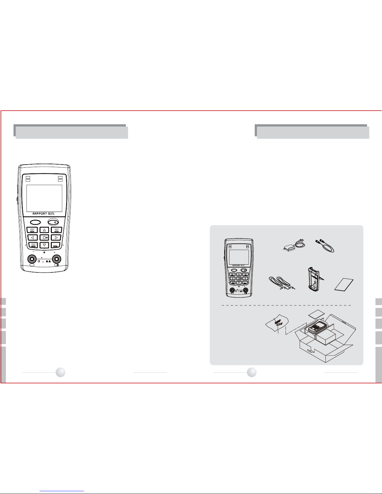
This basic instruction manual is for users of the Rapport mini. Starting with an outline of this
Rapport mini, the manual explains its operation,how it connects to other devices, how to
use the menu buttons,and how it should be operated.
It is highly recommended, even for those who have handled similar devices, as well as for
those using it for the first time, to read all the instructions thoroughly, especially the
precautions, before using the Rapport mini.
If there are any questions which arise when using the Rapport mini or the unit is damaged,
please contact the supplier of your Rapport mini.
Safety Information highlights and explains the precautions which should be taken, for the
safety of users, when using the Rapport mini.
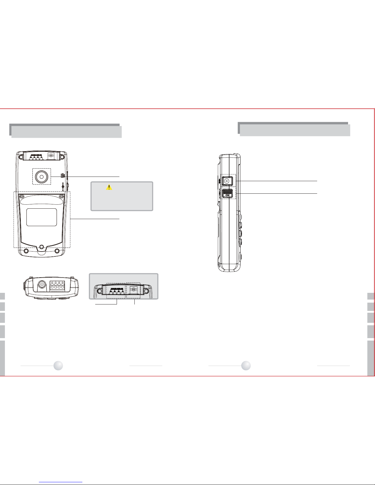
When using the Digital MultiMeter function to measure voltage, be sure
that the input does not exceed the capabilities of the tester. Overloading
the tester can cause damage or personal injury.
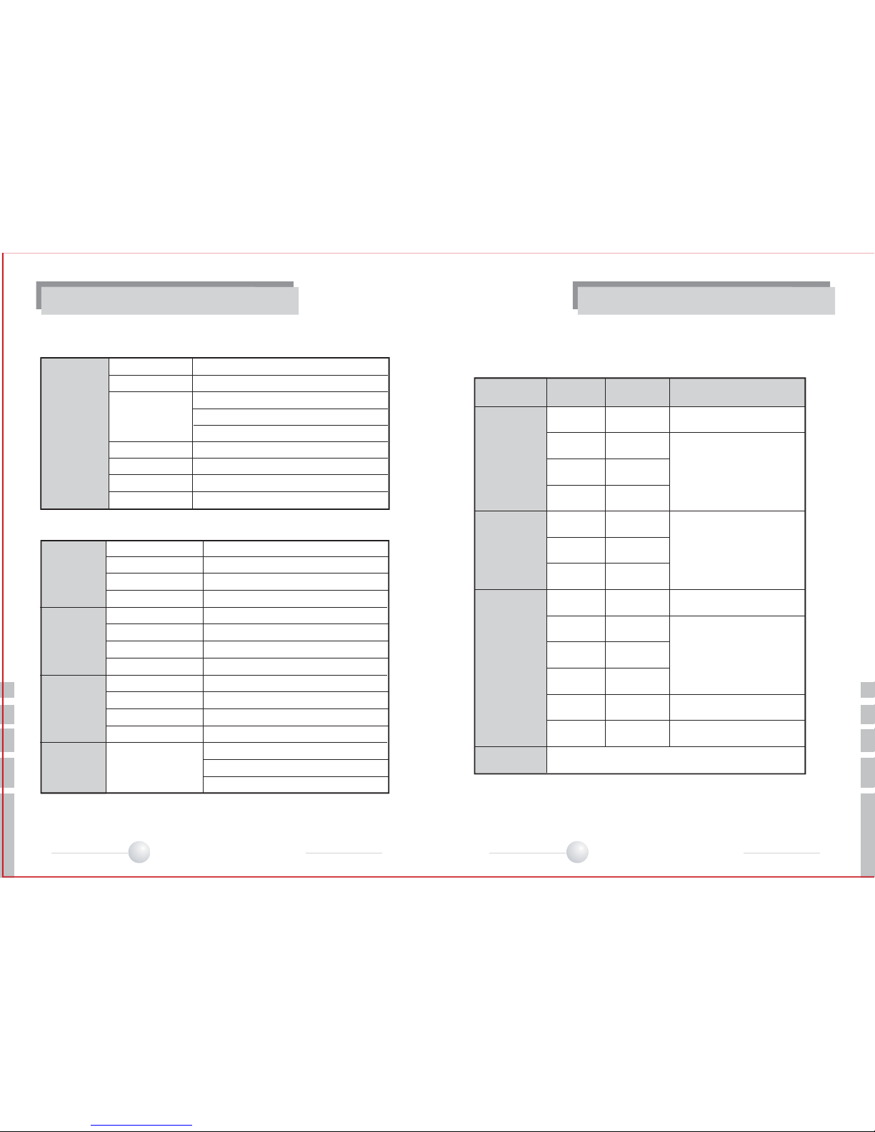
Environmental Limitations
Temperature: -10 to 40 degrees C
Relative Humidity: 30% -90%
DC input voltage: 12V +/-10%, 1A
Rapport mini Safety Precautions
-Use only specified replacement fuses.
-Do not use damaged test leads with the DMM.
-When using the DMM function, set the proper mode before connecting to the circuit
under test.
-When measuring resistance, make certain that the circuit is de-energized before
connecting the test leads to the circuit.
-Do not measure resistance on powered circuits.
-Do not use the unit in damp, humid or gaseous environments.
-Do not touch it with wet hands.
-Be mindful not to shock or shake the unit while in use to avoid damage.
-Avoid areas with strong magnetic or electromotive fields, which can cause incorrect
measurements.
-Remove the power plug from the outlet when there is a lightning storm.
-Neglecting to do so may cause fire or damage to the product.
-The Main plug is used as a disconnect device and shall stay readily operable at any
time.
-Be sure to use only the standard adapter that is specified in the specification sheet.
-Using any other adapter could cause fire, electrical shock, or damage to the product.
-Securely plug the power cord into the power receptacle. Insecure connection may cause
fire.
-If any unusual smells or smoke come from the unit, stop using the product. In such
case, immediately disconnect the power source and contact the service centre.
Continued use in such a condition may cause fire or electric shock.
-When cleaning, do not spray water directly onto parts of the product. Doing so may
cause fire or electric shock
SAFETY INFORMATION
04 MULTI FUNCTION CCTV TESTER 05 MULTI FUNCTION CCTV TESTER

FAR
OPEN
TELE
OSD
NEAR
CLOSE WIDE
COM V/
300V 300V~
MAX
V
~~♬
MODE SET
PWR
CHG
Tx
Rx
• Rapport mini • Accessories
BNC cablePower Adaptor
Test lead body cover
FAR
OPEN
TELE
OSD
NEAR
CLOSE WIDE
COM V/
300V 300V~
MAX
V
~~♬
MODE SET
PWR
CHG
Tx
Rx
RAPPORT MINI
MANUAL
manual
Rapport mini has a built-in Lithium Polymer
Battery.
It can be recharged using a DC12V power
adapter with an output of 1A or above and
reaches its full charge after a period in
excess of 5 hours. After the battery has been
fully charged for the first 2~3 charging
cycles, it can be used for approximately 6
hours (up to a Max.8 hrs in normal
operation).The battery can be recharged by
connecting it to the DC adapter, regardless of
OSD power, when the slider switch has been
turned on.
The discharge operation starts when the
Main Switch is turned on and it then
consumes power from the battery. Therefore,
when the Rapport mini is not being used for
a period of time, make sure the Main Switch
is turned off.
PRODUCT INTRODUCTION PRODUCT INTRODUCTION
Summary
StandardItems
Check the contents of your Rapport mini package against the standard checklist below :
Designed, with portability and serious CCTV engineers in mind, the Rapport mini is an
advanced piece of video test equipment consisting of many useful test functions
needed to professionally install a CCTV system; test functions include Service Monitor,
Multimeter, PTZ Test, RS-422 and RS-485 Communication Test, etc.
Test Leads
Adaptor
BNC to BNC Cable
RAPPOR MINI
MANUAL
• Rapport mini Package
06 MULTI FUNCTION CCTV TESTER 07 MULTI FUNCTION CCTV TESTER

FAR
OPEN
TELE
OSD
NEAR
CLOSE WIDE
COM V/
300V 300V~
MAX
V
~~♬
MODE SET
PWR
CHG
Tx
Rx
⑤
⑥
⑦
① ② ③ ④
MODE
SET
FAR
OPEN
TELE
OSD
NEAR
CLOSE
WIDE
COM V/
300V 300V~
MAX
V~♬
①②
①: Common Port, Lead for black colour
②: Voltage & Resistance Port, Lead for red colour
PRODUCT INTRODUCTION PRODUCT INTRODUCTION
Product Introduction
Power LED
Charge LED
Data Transmitting LED
Data Receiving LED
LCD
Keypad
MODE Button
SET Button
PTZ mode
Red LED is on when the system is switched on.
Green LED is on when the battery is fully charghed.
Red LED is on when PTZ data is transmitted.
Green LED is on when PTZ data is received.
2.5” Colour TFT LCD
Main keypad for Rapport mini operation
Mode Select: Video, MultiMeter, PTZ Control.
Used to confirm selection in menu screens.
(Press for 2 seconds to power on.)
Adjusts PTZ Focus Far Operation.
IRIS OPEN
Part Name Function
①
②
③
④
⑤
⑥
Part Name Function
Adjusts PTZ Focus Near Operation
IRIS Close
Adjusts PTZ Focus Zoom-in Operation
Clear OSD of PTZ mode
Adjusts PTZ Focus Zoom-out Operation
Moves PTZ Up/Down/Left/Right & Select Menu
Control Torch ON/ OFF button
PTZ mode
PTZ mode
PTZ mode
PTZ mode
Torch control
Test Lead Connection : Ports for Digital MultiMeter
V/
COM
08 MULTI FUNCTION CCTV TESTER 09 MULTI FUNCTION CCTV TESTER

①
②
①DC Power Jack : DC Power Input Jack (DC12V, 1A)
②Power Switch : Main Power Supply ON/OFF switch
①②
①Flash : White LED to light up in the dark area
②Internal Battery Cover
①Communication Port : Input & Output of PTZ communications signals
(RS 422/ RS485, Rx+, Rx-, Tx+, Tx- )
②Video Port : Select Video In and Video out in the Video mode
• Vin : Display input video signal to NTSC or PAL format.
• Vout : Transmit Standard Color-bar to external motor with NTSC or PAL format.
①
②
CAUTION
PRODUCT INTRODUCTION PRODUCT INTRODUCTION
DO NOT shine the torch light
directly into someone's eyes; it
could cause damage to their eyes.
10 MULTI FUNCTION CCTV TESTER 11 MULTI FUNCTION CCTV TESTER

Electrical
Characteristic
Video Mode
Input Voltage
Battery
Built-in charger
Display
Display Resolution
Working Temp.
Dimensions
DC 12V ± 10%, 1A
7.4V (3.7x2)Li-Poly, 2000mAh
Charging Time : 6 hour
Operation Time : Up to 8 hours hour
5 hour (Light HIGH ON), Continuous working
2.5" TFT-LCD (Digital), RGB666
320 x 240
-10℃~40℃
L159.3 x W79.1 x T32.2 (mm)
Electrical Specifications
Functional Specifications
Video IN / OUT
LCD Adjustment
Color bar generation
Signal Mode
Communication
PTZ Protocol
Baud rate
Rx Data Analyzer
DC Voltage Range
AC Voltage Range
Continuity
Resistance Range
ON / OFF
1CH, BNC ( IN/OUT selectable), 1.0 Vpp
Brightness, contrast
Standard Color bar (NTSC/PAL)
NTSC/PAL (Auto adapt)
RS422, RS485
Multi (24 protocols)
2400bps~38400bps
Hex Value Analysis
400mV/4V/40V/300V
4V/ 40V/300V
Built-in Buzzer sound
400Ω/4KΩ/40KΩ /400KΩ/4MΩ/40MΩ
-Viewing angle : about 60°
-Normal Operation : 5 hours continuous working
-Flash intensity :LOW/ MID/ High
PTZ
Controller
Digital
Multimeter
Torch Control
Mode Range Minimum
Measuring Accuracy
DC Voltage
400mV 100uV
4V 1mV
40V 10mV
300V 100mV
AC Voltage
4V 1mV
40V 10mV
300V 100mV
Resistance
400Ω 0.1Ω
4㏀ 1Ω
40㏀ 10Ω
400㏀ 100Ω
4㏀ 1㏀
40㏀ 10㏀
Continuity Beeper is activated when the resistance is below 80Ω
±(2.5% +4dgts)
±(2.5% +4dgts)
±(2.5% +4dgts)
±(2.0% +4dgts)
±(2.0% +2dgts)
±(2.0% +4dgts)
±(3.0% +5dgts)
(40㎐ ~ 500㎐)
Multimeter Specifications
Note:
Maximum voltage drop approx. 2V on the measuring current.
PRODUCT SPECIFICATION PRODUCT SPECIFICATION
12 MULTI FUNCTION CCTV TESTER 13 MULTI FUNCTION CCTV TESTER

Dimensions
159.3
66.5
63.8
FAR
OPEN
TELE
OSD
NEAR
CLOSE WIDE
COM V/
300V 300V~
MAX
V
~~♬
MODE SET
PWR
CHG
Tx
Rx
79.1
32.2
* L159.3 x W79.1 x T32.2 (mm)
PWR
CHG
Tx
Rx
OFF
OFF
ON
OFF
OFF
ON
OFF
Flicker(1 Hz)
Item RED LED GREEN LED
PRODUCT SPECIFICATION PRODUCT SPECIFICATION
LED Indicator
On charging : RED LED ON
Fully charged: GREEN LED ON
The LED turns Red or Green depending on the recharging status.
Discharged
Charging
Fully charged
Low battery
Battery is consumable item with 6 months warranty after purchase.
Use the manufacture provided adaptor only (DC12V/1A).
When Red LED flickers, reload battery or recharge battery.
14 MULTI FUNCTION CCTV TESTER 15 MULTI FUNCTION CCTV TESTER

MODE
MODE
MODE
제품소개
FAR
OPEN
TELE
OSD
NEAR
CLOSE WIDE
MODE SET
MODE SET
PWR
CHG
Tx
Rx
MODE SET
PWR
CHG
Tx
Rx
RAPPORT-MINI Ver : 0.03
[ Mode change ]
• Video Tester (Color CCTV Field Monitor )
• Color Bar Generator (Standard Video Signal Generator)
• Digital Multimeter
• PTZ Controller
• Receive Data Analyser
• Setup
• Torch ON / OFF
FAR
OPEN
TELE
OSD
NEAR
CLOSE WIDE
MODE SET
VIDEO NTSC
BRI 3CON 7
METER
VIDEO PTZ DATA SETUP
COLOR
0101
Functional use
Power ON/OFF
The power switch is located on the side of the handset.
Turn the power switch on, and press to start Rapport mini.
To turn off the system, press & hold for more than 2 sec. Then,
POWER OFF is displayed on the main screen with a beep. Release the
button. Turn the power switch OFF to prevent battery drain during storage.
The switch must remain ON to recharge the batteries.
A rechargeable battery should be plugged in over 5 hours to fully charge.
The charged battery can operate for about 8 hours.
When the battery indicator shows below , recharge it for use. (Full
charge: )
FUNCTIONAL SPECIFICATION
After the power is applied the above on-screen message is displayed.
Approximately 2 seconds later the screen switches to the last OSD before power
was turned off. The Rapport mini stores the last accessed OSD.
The initial OSD message displays the Rapport mini's firmware information. Versions of the
product change whenever new firmware is uploaded.
Modesetup
MainFunctions
The MODE SELECT menu is displayed when the key is depressed and
moves to the next menu whenever the key is pressed
The OSD menu changes whenever the key is pressed, and sequences
through in the following order :
VIDEO -> ColorBar -> Meter -> PTZ controller -> Receive Data -> SETUP
->VIDEO
SET
SET
16 MULTI FUNCTION CCTV TESTER 17 MULTI FUNCTION CCTV TESTER

[ Video Tester mode ]
VIDEO
IN
VIDEO NTSC
BRI 3CON 7
①
④
⑥ ⑦
②
③
⑤
VIDEO NTSC
[ Video Mode ]
①VIDEO : Indicates Current Mode.
②NTSC : Indicates NTSC or PAL System. (LOSS: No video)
③Indicates remaining battery.
④Indicates screen brightness, and brightness increases by +1 when the FAR
key is pressed, and decreases by -1 when the NEAR key is pressed.
⑤Indicates screen contrast, and contrast increases by +1 when the TELE key
is pressed, and decreases by -1 when the WIDE key is pressed.
⑥Indicates Mode, and changable by MODE button.
⑦Indicates SET & Indicates OSD clear button
[ OSD clear]
METER
VIDEO PTZ DATA SETUP
COLOR
0101
VIDEO NTSC
BRI 3CON 7
MODE CLR
제품소개 FUNCTIONAL SPECIFICATION
FUNCTIONAL SPECIFICATION
VideoTester
Connect the output terminal of video output system to the video BNC port of
Rapport mini.
( : DC Adaptor connected : Operated by Battery)
※ If there is no video signal at the VIDEO IN port of the
Rapport mini
“LOSS”
will be displayed.
18 MULTI FUNCTION CCTV TESTER 19 MULTI FUNCTION CCTV TESTER

ColourBarGeneratorMode
VIDEO NTSC
BRI 3CON 7
COLOR BAR NTSC
BRI 3CON 7
METER
VIDEO PTZ DATA SETUP
COLOR
0101
MODE FORMAT
①
④
⑥ ⑦
②
③
⑤
[ Color Bar Test mode ]
COLOR BAR NTSC
BRI 3CON 7
MODE FORMAT
COLOR BAR PAL
BRI 3CON 7
MODE FORMAT
[ NTSC ] [ PAL ]
VIDEO
OUT
VIDEO
제품소개 FUNCTIONAL SPECIFICATION
FUNCTIONAL SPECIFICATION
①VIDEO : Indicates Current Mode.
②NTSC : Indicates NTSC or PAL System. (LOSS: No video)
③Indicates remaining battery.
④Indicates screen brightness, and brightness increases by +1 when the FAR
key is pressed, and decreases by -1 when the NEAR key is pressed.
⑤Indicates screen contrast, and contrast increases by +1 when the TELE key
is pressed, and decreases by -1 when the WIDE key is pressed.
⑥Indicates Mode, and changable by MODE button.
⑦Indicates video format change (NTSC <-> PAL)
( : DC Adaptor connected : Operated by Battery)
To enter the PATTERN GENERATION MODE press the SET key while in the Colour bar mode.
By default the Video will be displayed in the top portion of the screen.
Outputs Colour bars allowing technicians to configure monitors and troubleshot cameras by
sending a known good video signal down a questionable coax run. Supports both PAL &
NTSC video signal formats.
C A U T I O N
Video teminal is selected by internal
firmware. Do not go into the Color bar
mode when the camera video is
connected.
20 MULTI FUNCTION CCTV TESTER 21 MULTI FUNCTION CCTV TESTER

METER
VIDEO PTZ DATA SETUP
COLOR
0101
METER
DC Ω
AC VOLT
ACV 0.042V
METER
AC Ω
DC VOLT
DCV+ 00.1mV
MODE STORE
[ Select Multimeter Mode ] [ Multimeter Mode ]
METER
DC Ω
AC VOLT
DCV+ 12.01V
DCV+ 12.02V
MODE STORE
①
④
⑥
⑦
⑧
②
③
⑤
⑨
Button for Multimeter mode
FAR
OPEN
TELE
OSD
NEAR
CLOSE WIDE
MODE SET
①②③
V
~~♬
①Voltage mode
②OHM(resistance) mode
③AC/DC, resistance/ continuity
제품소개 FUNCTIONAL SPECIFICATION
FUNCTIONAL SPECIFICATION
DigitalMultimeter
Voltage, resistance and continuity can be tested.
To prevent electric shocks, injury, or damage to the Rapport mini, disconnect
the power supply to the circuit under test, and discharge all high-voltage capacitors
before testing resistance and continuity.
When using the meter function of the Rapport mini, make sure the unit is
switched on and set to the appropriate test mode before connecting the test lead
set to the circuit under test.
W A R N I N G
Press the button to go into the multi meter mode.
Setup Keys
METER
※Sleep time is not operated in Multimeter mode.
(Sleep function -> see 34 page)
①METER : Indicates current mode.
②Indicates remaining battery.
③Indicates type of test set up :Resistance test, Continuity test, DC & AC Voltage.
④Indicates test mode : DCV > DC Voltage, ACV > AC Voltage, OHM> Resistance
BUZZ> Continuity
Indicates test value displayed : Resistance (Ω, kΩ, MΩ), voltage( V, mV), continuity(BUZZ)
⑤
⑦ Indicates measured value on hold :
The measure value is stored and displayed here when the SET key is pressed .
⑨ Indicates Store button by using SET button.
⑧Indicates mode display : Digital multimeter mode is displayed.
⑥Indicates measured graph value :
The Measured Input value is displayed in the form of a graph.
The graph is changed automatically and is equal to the measured value.
OVER is displayed when the measured value is higher than the setup value.
( : DC Adaptor connected : Operated by Battery)
22 MULTI FUNCTION CCTV TESTER 23 MULTI FUNCTION CCTV TESTER

METER
AC Ω
DC VOLT
DCV+ 12.01V
DCV+ 12.02V
MODE STORE
METER
DC Ω
AC VOLT
ACV 6.00V
MODE STORE
METER
AC
DC VOLT
OHM 9.86M
OHM 9.86M
MODE STORE
COM V/
300V 300V~
MAX
V
~~♬
COM V/
300V 300V~
MAX
V
~~♬
COM V/
300V 300V~
MAX
V
~~♬
Ω
COM V/
300V 300V~
MAX
V
~~♬
COM V/
300V 300V~
MAX
V
~~♬
METER
AC
DC VOLT
BUZZ 53.0
MODE STORE
Ω
제품소개 FUNCTIONAL SPECIFICATION
FUNCTIONAL SPECIFICATION
Measuring AC & DC Voltage
Voltage is the difference in electrical potential between two points.
The polarity of an AC voltage varies with time, while DC polarity is constant.
The meter displays AC voltage as RMS values (Root Mean Square readings).
The RMS value is the equivalent DC voltage measured in a time varying
sinusoidal signal.
(AC Voltage Test) (DC Voltage Test)
Measuring Resistance
The unit of resistance is the Ω. The meter sends a low current into the circuit so that
the resistance can be measured. This current runs along all paths between the two
probes and enables the total resistance to be calculated.
Continuity Testing
Continuity means the presence of a complete path for current to flow. The
continuity test features a beep that sounds when a circuit is complete. The beep
allows users to quickly test continuity without having to watch the display.
The beeper is activated when the resistance between the red and black probes is
less than 80Ω.
24 MULTI FUNCTION CCTV TESTER 25 MULTI FUNCTION CCTV TESTER

PTZ Control Button
VIDEO
IN
Tx-
Tx+ VIDEO
Tx- Tx+ Rx- Rx+
[ Select PTZ Control mode] [ PTZ Control mode ]
PTZ ADDR Setting PROTOCOL Setting
BAUDRATE Setting PARITY Setting
PTZ NTSC PTZ NTSC
①
④
⑥⑦
②
③
⑤
PTZ NTSC PTZ NTSC
PTZ NTSC
METER
VIDEO PTZ DATA SETUP
COLOR
0101
PTZ ADDR :001
PROTOCOL : (01)PELCO-D
BAUDRATE: 2 . 4Kbps
PARITY : NONE
SPD
15
GPST
001
SPST
001
FUNC
01
MENU
PTZ ADDR :001
PROTOCOL : (01)PELCO-D
BAUDRATE: 2 . 4Kbps
PARITY : NONE
SPD
15
GPST
001
SPST
001
FUNC
01
MENU
MODE SETUP
PTZ NTSC
PTZ ADDR :001
PROTOCOL : (01)PELCO-D
BAUDRATE: 2 . 4Kbps
PARITY : NONE
SPD
15
GPST
001
SPST
001
FUNC
01
MENU
MODE SETUP
PTZ NTSC
SPD
15
GPST
001
SPST
001
FUNC
01
MENU
MODE OK
PTZ ADDR :001
PROTOCOL : (01)PELCO-D
BAUDRATE: 2 . 4Kbps
PARITY : NONE
SPD
15
GPST
001
SPST
001
FUNC
01
MENU
MODE OK
PTZ ADDR :001
PROTOCOL : (01)PELCO-D
BAUDRATE: 2 . 4Kbps
PARITY : NONE
SPD
15
GPST
001
SPST
001
FUNC
01
MENU
MODE OK
PTZ ADDR :001
PROTOCOL : (01)PELCO-D
BAUDRATE: 2 . 4Kbps
PARITY : NONE
SPD
15
GPST
001
SPST
001
FUNC
01
MENU
MODE OK
PTZ ADDR :001
PROTOCOL : (01)PELCO-D
BAUDRATE: 2 . 4Kbps
PARITY : NONE
FAR
OPEN
TELE
OSD
NEAR
CLOSE WIDE
MODE SET
FUNCTIONAL SPECIFICATIONFUNCTIONAL SPECIFICATION
①VIDEO : Indicates Current Mode.
②NTSC : Indicates NTSC or PAL System. (LOSS: No video)
③Indicates remaining battery.
④Indicates PTZ Setting
-> PTZ ADDR : PTZ address setting ( 000~255)
-> PROTOCOL: PTZ protocol setting (24 Protocols)
-> BAUDRATE : Communication speed setting
(2.4Kbps, 4.8Kbps, 9.6Kbps, 19.2Kbps, 38.4Kbps)
-> PARITY: Parity bit setting (EVEN,ODD, NONE)
( : DC Adaptor connected : Operated by Battery)
PTZController
Connecting Camera and Monitor
PTZ Operation Test: Up, Down, Left, Right, Zoom and Manual focus control are
possible. The tester can also be set to various protocols and transmission
speeds (baud rates).
The PTZ SELECT menu is displayed when the PTZ key is pressed.
26 MULTI FUNCTION CCTV TESTER 27 MULTI FUNCTION CCTV TESTER

Each menu setting / value setting
ⓐ Go into the PTZ mode &
Exit button
ⓑ Change PTZ setting value
ⓒ Select PTZ setting
SET
SET
SET
SET
SET
FAR
OPEN
TELE
OSD
NEAR
CLOSE WIDE
MODE SET ⓐ
ⓑⓑ
ⓒ
ⓒ
PTZ NTSC
PTZ NTSC
MODE GO
MODE GO
SPD
15
GPST
001
SPST
001
FUNC
01
MENU
PTZ ADDR :001
PROTOCOL : (01)PELCO-D
BAUDRATE: 2 . 4Kbps
PARITY : NONE
SPD
15
GPST
001
SPST
001
FUNC
01
MENU
PTZ ADDR :001
PROTOCOL : (01)PELCO-D
BAUDRATE: 2 . 4Kbps
PARITY : NONE
PTZ NTSC
MODE GO
SPD
15
GPST
001
SPST
001
FUNC
01
MENU
PTZ ADDR :001
PROTOCOL : (01)PELCO-D
BAUDRATE: 2 . 4Kbps
PARITY : NONE
PTZ NTSC
SPD
15
GPST
001
SPST
001
FUNC
01
MENU
PTZ ADDR :001
PROTOCOL : (01)PELCO-D
BAUDRATE: 2 . 4Kbps
PARITY : NONE
MODE GO
FUNCTIONAL SPECIFICATIONFUNCTIONAL SPECIFICATION
- PTZ Control Setup Screen
Press and hold the SET button for 2seconds until PTZ protocol menu activates.
PTZ control (Up, Down, Left, Right), is performed using the arrow keys.
How to Control a PTZ Camera
SPD (SPEED) : Move the cursor to the SPD
icon, using the procedures described above.
A total of 16 increments in speed (0 to 15)
are available
for selection using the keys.
PTZ functions - Up, Down, Left, Right movements are carried out using the SET
Button. Focus and Zoom adjustments are made using the FAR/NEAR (Focus) and
TELE/WIDE (Zoom) buttons.
GPST (GO TO PRESET) : Moves the camera
view to a designated preset location; Presets
are numbered 000 to 255. The cursor moves
to the GPST position when the key is
pressed. Select the previously stored
PRESET number using the & keys
(move by+1, -1 step). Once selection is
complete, press the key once more
and the camera will move to the PRESET
location.
SPST (SET PRESET) : Sets and stores
PRESET information in the range from 000
to 255. First, move the camera to the
required view and press the key, and
use the & keys to place the cursor at
the location of the chosen preset. Then set
up the address where the preset is to be
stored by using the & keys, and
press the key once more. The
location information is now stored as a
preset address.
FUNC (Function): User can set different
functions that automatically load the presets
of the camera system. The FUNC setup uses
the SPST and MENU information buttons for
the user to program various presets. The
different number of presets can range from
00 all the way to 63. The functions (presets)
can be programmed by the (+1), (-1)
buttons and steps by using the &
keys.
28 MULTI FUNCTION CCTV TESTER 29 MULTI FUNCTION CCTV TESTER

PTZ OSD clear
PTZ NTSC PTZ NTSC
TELE
OSD
TELE
OSD
FAR
OPEN
TELE
OSD
NEAR
CLOSE WIDE
MODE SET
FAR
OPEN
TELE
OSD
NEAR
CLOSE WIDE
MODE SET
PTZ NTSC
PTZ NTSC
SPD
15
GPST
001
SPST
001
FUNC
01
MENU
MODE GO
PTZ ADDR :001
PROTOCOL : (01)PELCO-D
BAUDRATE: 2 . 4Kbps
PARITY : NONE
MODE SETUP
MAIN MENU
DOME
CAMERA
MOTION
DISPLAY
CLEAR DATA
EXIT
SPD
15
GPST
001
SPST
001
FUNC
01
MENU
MODE SHIFT SETUP
PTZ ADDR :001
PROTOCOL : (01)PELCO-D
BAUDRATE: 2 . 4Kbps
PARITY : NONE
MODE SHIFT SETUP
DATA RCV NTSC
METER
VIDEO PTZ DATA SETUP
COLOR
0101
VIDEO
Tx- Tx+ Rx- Rx+
VIDEO
IN
RX-
RX+
TX-
TX+
FUNCTIONAL SPECIFICATIONFUNCTIONAL SPECIFICATION
MENU :
Activates the PTZ camera’s internal menu. PTZ cameras have an on-screen menu
system that allows Rapport mini to program various functions of the camera including
day/night mode, focus settings, and tours. When a tour is programmed into the camera it
can be activated with Rapport mini using the TOUR function in the menu.
MODE :
Change the menu.
SETUP :
Setup the PTZ Camera menu.
OSD Clear :
When you press button in the PTZ mode, the PTZ OSD clear button is
activated and press the button, the PTZ OSD is cleared.
DATA:
When you want to know the input signal of an exterior controller, you can see the input
data(HEX value) by connecting the communications cable to the RX terminal of the
Rapport mini. The control commands from the keyboard of an external controller are
displayed on the screen. Most important is that the communication speed are matched.
30 MULTI FUNCTION CCTV TESTER 31 MULTI FUNCTION CCTV TESTER

MODE
[ Clear received data ]
DATA RCV
MODE CLEAR
FF 00 00 FF 01 00 00
FF 01 00 02
3B 3B
79
FF 01 00 02
3B 3B
79
FF 01 00 00 00 00 01
①
③
④⑤
②
DATA RCV
MODE CLEAR
FF 00 00 FF 01 00 00
FF 01 00 02
3B 3B
79
FF 01 00 02
3B 3B
79
FF 01 00 00 00 00 01
DATA RCV
MODE CLEAR
SET
[ Select SETUP mode ] [ SETUP mode ]
SETUP
METER
VIDEO PTZ DATA SETUP
COLOR
0101
USER NAME : RAPPORT - MINI
SLEEP TIME : 30Min
BEEP : ON
FLASH LVL : HIGH
SETUP
USER NAME : RAPPORT - MINI
SLEEP TIME : 30Min
BEEP : ON
FLASH LVL : HIGH
MODE
SETUP
USER NAME : RAPPORT - MINI
SLEEP TIME : 30Min
BEEP : ON
FLASH LVL : HIGH
MODE
①②
③
④
FUNCTIONAL SPECIFICATIONFUNCTIONAL SPECIFICATION
①DATA RCV : Indicates Current Mode.
②Indicates remaining battery.
③Indicates received data.
④Indicates change mode.
⑤Indicates data clear on the screen. (Press SET button to operate it)
( : DC Adaptor connected : Operated by Battery)
①SETUP : Indicates Current Mode.
②Indicates remaining battery.
③Indicates setup items.
④Indicates change mode.
( : DC Adaptor connected : Operated by Battery)
Select a menu item by pressing the & keys.
Each setup value can be changed by pressing the & keys
Mode Select : To access this menu depress the key and select the
SETUP icon.
Setup
32 MULTI FUNCTION CCTV TESTER 33 MULTI FUNCTION CCTV TESTER

SETUP
USER NAME : RAPPORT - MINI
SLEEP TIME : 30Min
BEEP : ON
FLASH LVL : HIGH
MODE
SETUP
BACK
USER NAME
RAPPORT - MINI
0123456789()ABCDEFGHIJKLM
NOPQRSTUVWXYZ!@#$% & +-+<>
FLASH ON/OFF & Level Change
Flash Level
- OFF
- LOW
- MID
- HIGH
Torch
OFF
Press 2 seconds Press 2 secondsFLASH ON
SETUP
USER NAME : RAPPORT - MINI
SLEEP TIME : 30Min
BEEP : ON
FLASH LVL : HIGH
MODE
SETUP
USER NAME : RAPPORT - MINI
SLEEP TIME : 30Min
BEEP : ON
FLASH LVL : HIGH
MODE
SETUP
MODE
USER NAME : RAPPORT - MINI
SLEEP TIME : 30Min
BEEP : ON
FLASH LVL : HIGH
FUNCTIONAL SPECIFICATIONFUNCTIONAL SPECIFICATION
Selecting the USER NAME initiates an editing menu and shows the associated
key strokes.
BUZZER: Select a menu item by pressing
the & keys.
Each setup value can be
changed by pressing the
& keys (ON/OFF)
SLEEP TIME: Select sleep time by using
the & buttons and change
sleep options by using the
& buttons. The options
are OFF, 1, 5, 10, 30, 60 minutes.
Select a menu item by pressing the & keys.
Each setup value can be changed by pressing the & keys
Select a menu item by pressing the & keys.
Flash level can be changed by pressing the & keys
To turn on or turn off, use the button for 2 seconds.
※ Sleep time makes the power go OFF automatically,
unless the button is pressed.
※Torch fucntion is not worked in SETUP mode but only Torch level setting is available.
34 MULTI FUNCTION CCTV TESTER 35 MULTI FUNCTION CCTV TESTER

MEMO
Number
1
2
3
4
5
6
7
8
9
10
11
12
13
Direct current
Alternating current
3
Symbol Description
Both direct and alternating current
Three-phase alternating current
Earth (ground) TERMINAL
PROTECTIVE CONDUCTOR TERMINAL
Frame or chassis TERMINAL
Equipotentiality
On(Supply)
Off(Supply)
Equipment protected throughout
by DOUBLE INSULATION or
REINFORCED INSULATION
Caution, rick of electronic shock
Caution, hot surface
IRE 60417 - 5031
Reference
IRE 60417 - 5032
IRE 60417 - 5033
IRE 60417 - 5017
IRE 60417 - 5019
IRE 60417 - 5020
IRE 60417 - 5021
IRE 60417 - 5007
IRE 60417 - 5008
IRE 60417 - 5172
IRE 60417 - 5041
**The equipment shall not be used for measurements of categories II, III and IV.
**If the equipment is used in a manner not specified by the manufacturer, the protection provided by the
equipment may be impaired.
SYMBOLS
TABLE 1 - SYMBOLS
36 MULTI FUNCTION CCTV TESTER

Table of contents
Popular Test Equipment manuals by other brands

Shimpo
Shimpo DT-311J instruction manual

MONARCH INSTRUMENT
MONARCH INSTRUMENT PALM STROBE x instruction manual

Baker Hughes
Baker Hughes Druck DPI 620 Genii Safety Instructions and User Guide

Jula
Jula Meec Tools 405-056 User instructions

Rosenberger
Rosenberger 19CK010-150 user manual

Vitlab
Vitlab piccolo 1 operating manual