Firmtech FBL601BC Series User manual


FBL601BC_serial User Guide Version 1.0
Revision History
페이지 2 / 12
Revision History
Revision
Date
Change Descriptions
Ver 1.0
2022-09-15
- Write a draft

FBL601BC_serial User Guide Version 1.0
(C) Copyright FIRMTECH Co., Ltd. 2005
페이지 3 / 12
(C) Copyright FIRMTECH Co., Ltd. 2005
All rights reserved
The products and operation descriptions contained herein shall be protected by
copyright law.
Any part or whole of products or operation description shall not be copied, reproduced,
translated, nor transformed into readable form by electronic device or machines, without
prior consent in writing by FIRMTECH Co., Ltd.
There might be some misprinting or technical faults in the products and operation
description which are subject to change without prior notice.

FBL601BC_serial User Guide Version 1.0
List of Content
페이지 4 / 12
List of Content
Revision History ...........................................................................................................................2
(C) Copyright FIRMTECH Co., Ltd. 2005.......................................................................................3
List of Content.............................................................................................................................4
1 What is Bluetooth? ...................................................................................................................5
1.1 Features of Bluetooth......................................................................................................5
1.2 Operation of Bluetooth ...................................................................................................5
2 Product Overview .....................................................................................................................6
3 Product Components................................................................................................................6
3.1 FBL601BC_serial .............................................................................................................6
3.2 Interface Board (Option) .................................................................................................6
4 FBL601BC_serial Appearance....................................................................................................7
4.1 FBL601BC_serial Dimension ............................................................................................7
4.2 FBL601BC_serial PIN Assign ............................................................................................8
5 Interface (Pin Connection) ........................................................................................................9
6 Interface Board (Jig Board)......................................................................................................10
7 Specification of FBL601BC_serial ............................................................................................11
8 Current Consumption .............................................................................................................12
9 Preliminary Product Components ............................................................................................12

FBL601BC_serial User Guide Version 1.0
1 What is Bluetooth?
페이지 5 / 12
1 What is Bluetooth?
1.1 Features of Bluetooth
Objectives of Bluetooth : To Realize Wireless Communication for Short Distance with Low Power
Consumption, High Reliability, and Low Cost.
Frequency in Use: To Use ISM(Industrial, Scientific, Medical) Band which does not require any
permission to use.
-2.400 –2.4835 GHz, 79 channels
-2.465 –2.4835 GHz, 23 channels (in France)
Transmission Rate : 1Mbps ~ 3Mbps
Transmission Output : 1mW (10m, Class2), 100mW (100m Class1)
Network Configuration : Configured with Master and Slave relation. A Bluetooth unit shall allow
simultaneous connections up to 7 devices (in case of ACL).
Reliability : To Guarantee stable wireless communication even under severe noisy environment
through adopting the technique of FHSS (Frequency Hopping Spread Spectrum).
1.2 Operation of Bluetooth
<Feature 1-1 Bluetooth Operation>
Bluetooth operates based on the connection between “Master”and “Slave”.
Masters are simply supposed to do “Inquiry”and “Page”. Slaves are supposed to do “Inquiry Scan”
and “Page Scan”.
If a Master finds a Slave and so “inquiry”is successful, a Slave responds to the Master with its
information.
Interconnection between the Master and the Slave is achieved only if the information from the Slave is
corresponded with the Master, and the Slave sends data to the Master.

FBL601BC_serial User Guide Version 1.0
2 Product Overview
페이지 6 / 12
2 Product Overview
Major Features of FBL601BC_serial
1. Bluetooth Specification 5.2 Low Energy Support
2. Easily Applicable to the Product with 8 Pins Header Type
3. Support AT Command, and capable to control FBL601BC_serial by using AT Command
4. UART can be used as an interface
※We request the new users of FBL601BC_serial to read the information on this description carefully before
they start to use the products.
3 Product Components
3.1 FBL601BC_serial
MODEL
PICTURE
Q’TY (EA)
FBL601BC_serial
(On-board Chip Antenna)
1
<Table 3-1 Basic Components of FBL601BC_serial >
3.2 Interface Board (Option)
MODEL
PICTURE
Q’TY (EA)
Interface Board
1
<Table 3-2 Components of Interface Board >
※If you find any of above components is defective, or not included in the package, please contact the seller
you purchased.

FBL601BC_serial User Guide Version 1.0
4 FBL601BC_serial Appearance
페이지 7 / 12
4 FBL601BC_serial Appearance
4.1 FBL601BC_serial Dimension
[Top View]
[Side View]
<Figure 4-1 FBL601BC_serial Dimension>

FBL601BC_serial User Guide Version 1.0
4 FBL601BC_serial Appearance
페이지 8 / 12
4.2 FBL601BC_serial PIN Assign
<Figure 4-2 FBL601BC_serial PIN Assign>
NO
Name of Signal
Features
I / O
Level
1
GND
Ground
2
VCC
DC 3.3V
3
STATUS
Operation Status
Output
TTL
4
FA_SET
CONFIG_SELECT
Factory Reset
Configuration Select
Input
TTL
5
Power Save Control
Power Save On/Off Control
Input
TTL
6
NC
No Connect
-
-
7
TXD
Transfer Data (Data out)
Output
TTL
8
RXD
Received Data (Data in)
Input
TTL
<Table 4-1 Pin Description>
- STATUS port
To be used to monitor the status of FBL601BC_serial
It keeps LOW (0V) when the Bluetooth wireless section is connected smoothly and both devices can
communicate
In standby mode for connection with Bluetooth, or connection trial, or searching for around Bluetooth
device will repeat LOW and HIGH.

FBL601BC_serial User Guide Version 1.0
5 Interface (Pin Connection)
페이지 9 / 12
-FA_SET / CONFIG_SELECT
If you want to enter the configuration mode, turn on the power to the module while inputting LOW Signal
(0V) to Configuration Select (No. 4 pin).
If you want to change to the factory default value, enter the LOW Signal (0V) for more than 5 seconds into
the Factory Reset (Pin No. 4) after entering the configuration mode and all setting values will be changed to
the original purchase status.
- Power Save Control Port
Select FBL601BC_serial's Power Save ON/OFF Control When high is applied it operates as Power Save On
When low is applied, it operates as power save off.
5 Interface (Pin Connection)
<Figure 5-1 Pin Connection Control>

FBL601BC_serial User Guide Version 1.0
6 Interface Board (Jig Board)
페이지 10 / 12
6 Interface Board (Jig Board)
<Figure 6-1 Interface Board>
No.
Title
Description
1
UART communication & power port
UART communication interface terminal for PC connection
5V power input terminal
2
Power ON/OFF Switch
Interface Board Power On/Off Switch
3
STATUS LED
USB LED: USB port status LED
POWER LED: 3.3V power supply LED
STATUS LED: Status confirmation LED
RX LED: UART input confirmation LED
TX LED: UART Output confirmation LED
4
Configuration Select Switch
Switch for enter the configuration mode
The configuration entry mode method is as follows.
①Hold CONFIG switch and power on..
②Enter the configuration mode completed
Factory Reset Switch
Factory initialization switch
The Factory initialization is as follows.
①Enter the configuration mode
②After entering configuration mode, press the FASET
switch Hold for 5 seconds.
③Factory initialization completed
5
Connection connector
FBL601BC_serial Connection connector
<Table 6-1 PC Interface Board>

FBL601BC_serial User Guide Version 1.0
7 Specification of FBL601BC_serial
페이지 11 / 12
7 Specification of FBL601BC_serial
No.
Part
Specification
1
Bluetooth Spec.
Bluetooth Specification 5.2 Low Energy Support
2
Communication distance
10 M
3
Frequency Range
2402 ~ 2480 MHz ISM Band
4
Sensitivity
-79dBm (Typical)
5
Transmit Power
0dBm(Typical)
6
Size
15.50mm x 18.50 mm x 12.34mm
7
Support Bluetooth Profile
GATT Service
8
Input Power
3.3V
9
Current
Consumption
Peripheral
2.1mA(Max : Power Save Off)
Central
4.5mA(Max : Scanning)
10
Temperature
Operating
-10℃ ~ 50℃
Limit Operating
-40℃ ~ 85℃
11
Communication Speed
9,600bps –115,200bps
12
Antenna
Chip Antenna
13
Interface
UART (TTL Level)
<Table 7-1 FBL601BC_serial Specification>

FBL601BC_serial User Guide Version 1.0
8 Current Consumption
페이지 12 / 12
8 Current Consumption
Status
Current Consumption (mA)
MIN
MAX
AVG
Ready
1.79
1.79
1.79
Advertising
1.86
1.97
1.90
Connection
1.92
1.94
1.93
< Table 8-1 Peripheral Current Consumption of FBL601BC_serial>
Status
Current Consumption (mA)
MIN
MAX
AVG
Ready
1.87
1.87
1.87
Scanning
4.25
4.48
4.32
Connection
1.95
1.97
1.96
< Table 8-2 Central Current Consumption of FBL601BC_serial>
TEST CONDITIONS
Baud Rate : 9600 bps, Input Voltage : DC 3.3V
The power consumption will change depending on transmission speed and volume of data.
9 Preliminary Product Components
The preliminary value of product is set as on the <Table 9-1>.
Please be sure of basic set value and so on before using the product.
Type
Set Value
Device Name
FBL601(XXXXXX)
Uart (baud rate-data bit-parity bit-stop bit)
9600-8-N-1
ROLE
Peripheral
Advertising Interval
100ms
Connection Interval
12ms
<Table 9-1 Preliminary Configuration Setting Value for FBL601BC_serial>
※FBL601BC_serial can change the setting value by using AT command of Bluetooth setting.

FCCMODULARAPPROVALINFORMATIONEXAMPLESforManual
ThisdevicecomplieswithPart15oftheFCCRules.Operationissubjecttothefollowingtwoconditions:
(1) Thisdevicemaynotcauseharmfulinterference.
(2) Thisdevicemustacceptanyinterferencereceived,includinginterferencethatmaycause
undesiredoperation.
CAUTION:Changesormodificationsnotexpresslyapprovedbythepartyresponsiblefor
compliancecouldvoidtheuser'sauthoritytooperatetheequipment.
NOTE:ThisequipmenthasbeentestedandfoundtocomplywiththelimitsforaClassBdigitaldevice,
pursuanttoPart15oftheFCCRules.Theselimitsaredesignedtoprovidereasonableprotectionagainst
harmfulinterferenceinaresidentialinstallation.Thisequipmentgeneratesusesandcanradiateradio
frequencyenergyand,ifnotinstalledandusedinaccordancewiththeinstructions,maycauseharmful
interferencetoradiocommunications.However,thereisnoguaranteethatinterferencewillnotoccur
inaparticularinstallation.Ifthisequipmentdoescauseharmfulinterferencetoradioortelevision
reception,whichcanbedeterminedbyturningtheequipmentoffandon,theuserisencouragedtotry
tocorrecttheinterferencebyoneormoreofthefollowingmeasures:
‐Reorientorrelocatethereceivingantenna.
‐Increasetheseparationbetweentheequipmentandreceiver.
‐Connecttheequipmentintoanoutletonacircuitdifferentfromthattowhichthereceiveris
connected.
‐Consultthedealeroranexperiencedradio/TVtechnicianforhelp.
FCCRadiationExposureStatement:
ThisequipmentcomplieswithFCCradiationexposurelimitssetforthforanuncontrolledenvironment.
Thisequipmentshouldbeinstalledandoperatedwithminimumdistance20cmbetweentheradiator&
yourbody.
OEMINTEGRATIONINSTRUCTIONS:
ThisdeviceisintendedonlyforOEMintegratorsunderthefollowingconditions:
The module must be installed in the host equipment such that 20cm is maintained between the
antenna and users, and the transmitter module may not be co‐located with any other transmitter or
antenna. The module shall be only used with the internal on‐board antenna that has been originally
tested and certified with this module. External antennas are not supported. As long as these 3
conditionsabovearemet,furthertransmittertestwillnotberequired.
However,theOEMintegratorisstillresponsiblefortestingtheirend‐productforanyadditional
compliancerequirementsrequiredwiththismoduleinstalled(forexample,digitaldeviceemissions,PC
peripheralrequirements,etc.).Theend‐productmayneedVerificationtesting,Declarationof
Conformitytesting,aPermissiveClassIIChangeornewCertification.PleaseinvolveaFCCcertification
specialistinordertodeterminewhatwillbeexactlyapplicablefortheend‐product.
Validityofusingthemodulecertification:
In the event that these conditions cannot be met (for example certain laptop configurations or co‐
locationwithanothertransmitter),thentheFCCauthorizationforthismoduleincombinationwiththe
hostequipmentisnolongerconsideredvalidandtheFCCIDofthemodulecannotbeusedonthefinal
product. In these circumstances, the OEM integrator will be responsible for re‐evaluating the end
product (including the transmitter) and obtaining a separate FCC authorization. In such cases, please
involve a FCC certification specialist in order to determine if a Permissive Class II Change or new
Certificationisrequired.
UpgradeFirmware:
ThesoftwareprovidedforfirmwareupgradewillnotbecapabletoaffectanyRFparametersascertified
fortheFCCforthismodule,inordertopreventcomplianceissues.
Informationthatmustbeplacedintheendusermanual:
TheOEMintegratorhastobeawarenottoprovideinformationtotheenduserregardinghowtoinstall
orremovethisRFmoduleintheuser'smanualoftheendproductwhichintegratesthismodule.Theend
usermanualshallincludeallrequiredregulatoryinformation/warningasshowinthismanual.
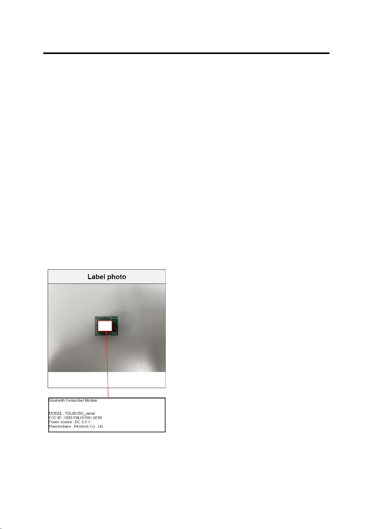
End product labeling:
Table of contents
Other Firmtech Network Hardware manuals


Popular Network Hardware manuals by other brands


Digital Watchdog
Digital Watchdog VMAX ip PLUS DW-VP92T4P quick start guide

OWC
OWC MINISTACK STX user guide

rock space
rock space RSD0610 Quick installation guide

Cimetrics
Cimetrics B6130 Setup / configuration

ADTRAN
ADTRAN Total Access 300 Series Installation and maintenance guide

Mobatime
Mobatime DTS 2440.audio-clock instruction manual