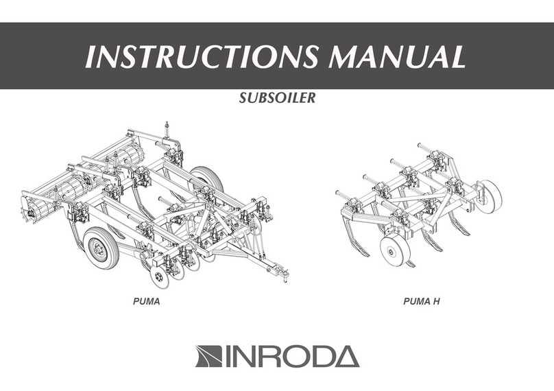
INRODA Light Duty Disc Harrow User manual

Light Duty Disc Harrow
DESBRAVADORA PREMIUM
INSTRUCTIONS MANUAL

THE PREMIUM DESBRAVADORA IS USED FOR MOVE AND LEVELING GROUND, AND
INCORPORATING HERBICIDES INTO THE SOIL, LEAVING IT IN IDEAL CONDITION
FOR PLANTING. IT WAS DEVELOPED WITH THE HIGHTEST LEVEL OF QUALITY AND
RESISTANCE AND CAN BE TRANSPORTED USING THE TRACTOR’S THREE POINTS. IT
HAS HIGHT RESISTANT DISCS AND BEARINGS LUBRICATED BY OIL OR GREASE.

01
01 - Introduction
- Warranty
02 - Parts:
- Light duty disc harrow
03 - Safety Rules
- Transportation by trucks/semi-trailers
04 - Technical Specifi cations
05 - Assembly:
- Disc Gang Assembly
- Bearing mount
- Joining the structures
- Locking handle assembly
- Coupling tongue assembly
06 - Coupling:
- Coupling with the tractor’s Hydraulics for transportation or harrowing
- Coupling the harrow with the Tractor’s Traction Bar
07 - Adjustments and Operations:
- Harrow opening adjustments
- Moving the harrow
- Starting the harrow
- Operations
08 - Maintenance:
- Lubrication
- Grease roller bearings
- Oil bath roller bearings
- Lubrication points
- Bearing adjustments
09 - Calculating the harrow’s hourly yield
- Table of approximate production
10 - Cleaning
11 - Genuine Parts
12 - Identifi cation
02
03
04
05
07
08
09
10
11
11
11
12
13
13
14
14
15
16
17
17
17
18
19
20
21
22
22
22
TABLE OF CONTENT
HARROW OPENING ADJUSTMENTS

02
INTRODUCTION
This manual is an important part of your machine provided by IN-
RODA Indústria de Roçadeiras Desbravador Avaré Ltda and should re-
main with the machine when you sell it.
Reading your operator’s manual will help you and others avoid per-
sonal injury or damage to the machine. Information given in this manual
will provide the operator with the safest and most effective use of the ma-
chine. Knowing how to operate this machine safely and correctly will allow
you to train others who may operate this machine.
The dealer will delivery the equipments and explain about safe
working, maintenance technical support and provide further details about
the terms and conditions of the warranty.
To obtain performance of the warranty, the original purchaser must
request warranty service from a distributor authorized to sell the product to
be serviced .
Following the instructions of this manual and correct maintenance it
will provide a long years of trouble-free from your implement.

03
WARRANTY CERTIFICATE
INRODA Indústria de Roçadeiras Desbravador Avaré Ltda., as manufacturer warrants all parts, (except those referred to below), of the product
described in this manual to be free from defects in materials and workmanship during the period of 6 (six) month from the invoice date to the first
purchaser following the rules bellow :
WARRANTY COVER
The warranty will cover defective parts not subject to normal wear and tear will be repaired or replaced at our option during the warranty period
when the use follow the content of this manual.
To requesting the warranty is necessary show the warranty certificate and invoice with all fields filled in observance of the warranty rules.
WARRANTY VOID CONDITIONS
This warranty does not apply to equipment or parts that have been subjected to improper or unauthorized installation or alteration and modifica-
tion, misuse, negligence, accident, overloading, overspeeding, improper maintenance, repair or storage so as, in our judgment, to adversely affect its
performance and reliability;
Failure to follow recommended operating and maintenance procedures, including maintenance in dealer unauthorized by the manufacturer, also
voids warranty
Maintenance and replacement of parts by not genuine INRODA parts;
Project changes also void the warranty;
Incomplete or incorrect filling of the warranty certificate.
THE WARRANTY DOES NOT COVER:
Damages caused by accidents;
Part damaged by the normal wear unless problems from defects in materials and workmanship.
Fluids and lubricate oil;
Transportation charges on product submitted for repair or replacement under this warranty must be borne by purchaser.
GENERAL CONDITIONS
All equipment and parts replaced under this warranty will become the property of the manufacturer, INRODA;
The warranty of parts replaced are limited of the equipment warranty period above described.
Delay in warranty services does not provide right to reimbursement, indemnification or extending the warranty

04
LIGHT DUTY DISC HARROW
01 - Coupling tongue
02 - Disc axle
03 - Axial bearing
04 - Disc
05 - Front frame
06 - Rear frame
07 - Complete locking handle
08 - Opening adjustment bar
02 - PARTS
02
01
03
06
05
04
07
08
DRAWING 01

05
03 - SAFETY RULES
THIS IS THE SAFETY ALERT SYMBOL. IT IS USED TO ALERT YOU TO POTENTIAL PERSONAL INJURY HAZARDS.
OBEY ALL SAFETY MESSAGES THAT FOLLOW THIS SYMBOL TO AVOID POSSIBLE INJURY OR DEATH.
1 - When operating the equipment, do not allow people to be near to or on top of the equipment.
2 - Do not start the tractor’s engine in an enclosed space without adequate ventilation. The gases that are emitted are harmful to your health.
3 - When turning on or off the hydraulic hoses, alleviate the circuit pressure.
4 - Periodically check the condition of the hoses. If there is any indication of leaking oil, immediately replace the hose. Oil under high pressure can
cause serious injuries.
5 - Do not make adjustments with the equipment turned on.
6 - When driving the tractor on roads, keep the brake pedals interconnected.
7 - When servicing, assembling, or disassembling the disk sections, use gloves.
8 - When positioning the tractor for hitching with the equipment, make sure that you have suffi cient space and that no one is very near. Always
maneuver the tractor in a low gear at a low speed and be prepared to brake in the case of an emergency.
9 - Do not use loose-fi tting clothing because it could become caught in the equipment.
10 - Always drive the tractor at safe speeds, especially on uneven or inclined terrain. Always keep the tractor hitched.
11 - When working on inclined surfaces, proceed with caution in order to maintain constant stability. If you start to experience problems with stability,
reduce your speed, turn the wheels away from the incline and never raise the equipment.

06
12 - When starting the tractor’s engine, sit correctly in the operator’s seat and be completely aware of the correct and safe operating procedures of
both the tractor and the equipment. Always put the gearstick in the neutral position, turn off the gear system of the power take-off control and put the
hydraulic controls in the neutral position.
13 - Do not do work with the tractor front too light if there is a tendency of lift up add more extra-weight in its front or in the wheels.
14 - When leaving the tractor, set gear in the neutral position and apply the parking brake. Never leave the equipment hitched to the tractor with the
hydraulic system in the raised position.
WARNING: The incorrect handing of this implement may result in serious injuries or death. Before using the implement read
carefully the instruction manual. Be sure that the person responsible for the operation is instructed about the correct handing
and safety and has understood the instruction manual concerning this machine.

07
TRANSPORT BY TRUCK
The transport in long distances must be done by a truck or another vehicle able to doing it, following the instruc-
tions below:
- For loading and unload the rotary cutter use proper ramps Do not use hilly places it may result in
serious injuries or death
- For unloading the rotary cutter use proper anchor points .
- Lock the rotary cutter on the vehicle during the transport.
- Use the proper devices (rope, chain, wire) to attaching the rotary cutter during the transport procedures
- Inspect the rotary cutter after 8km then check ropes and attachment devices every 100km traveled
- Pay attention about the transport height because electrical power lines overhead or in bridges may
result in serious injuries or death..
- Inform about local laws height and width requirements when necessary follow the regulations for lighting
requirements be sure turn signal lights and tail lights are clean and visible.

08
TABLE 01
50 - 150
1.1/4”
Number of
Disks
Cutting width
(mm)
Disk Axle
diameter
Weight (kg)
Disk 20”
Working depth
(mm)
Tractor
required
20 1700
24 2100
28 2350
32 2700
36 3000
42 3600
500
575
630
720
765
870
50 - 60
60 - 65
70 - 75
80 - 90
85 - 95
95 - 100
Dimensions
18” x 4 mm
Or
20” x 4 mm
Espacing
175 mm
04 - TECHNICAL FEATURES

09
1 - During the parts inspection in the package
2 - Wear PROTECTIVE GLOVES before doing anything.
- Put the convex washer (2), the nut (3), the nut lock (4) on the shaft (1) and
attach with the bolt (5). Note that the shaft should be fl ush with the nut.
- Add to the shaft (1), a disc (6), a bearing (7), another disc (6), a spool (8),
and the repeat this procedure as shown in fi gure 2.
- When mounting harrow 20, 36, and 42 discs with spacing of 175 mm,
place the spools on the inner side of the harrow, as shown in fi gure 02
- When fi nished with the whole gang, each disc and spool, put on a concave
washer (10), and nut (3), tightening until the whole gang is tight.
- Having done this, lock the disc gang and tighten the nut (3) using impacts.
- When you have made it as tight as possible, adjust The nut lock (4) with
a washer (10), always tightening the nut until it is fl ush, attach it using the
bolt (5), the washers and nuts.
05 - ASSEMBLY
When using roller bearings, they should be mounted with the lubrica-
tion system (plug or grease nipple must be turned to the rear side) as
shown in Drawing 03.
02
01
03
06
05
04
07
06
08
09
10
03
04
05
DRAWING 02
DRAWING 03
ATTENTION
07
View of the front and rear mounted
gang with the lubrication system at
the rear of the equipment to provide
the best protection.
NOTE

10
DISK GANG ASSEMBLY
20 DISCS
* 175 mm
24 DISCS
* 175 mm
28 DISCS
* 175 mm
32 DISCS
* 175 mm
36 DISCS
* 175 mm
42 DISCS
* 175 mm
These fi gures show the assembly of the disk sections for
each harrow model.
The disc smallest in diameter should be attached at
the ends of each disc gang.
During assembly, make sure that the parts are in the
correct position, that the disk concavities are aligned
with the thrust washers, the bearings, and the spools.
DRAWING 04
NOTE
IMPORTANT
LEGENDA
= BEARING
= SPOOL
= DISC

11
BEARING ATTACHMENT MOUNT
Hitch the front frame
(1) to the rear frame
(2) using the joining
pin (3) and lock it in
place with the cotter
pin (4), as shown in
Drawing 06.
Insert the adjustment bar (2) into the adjuster (1), attaching it with the pin
(3), washer, and safety bolt (4). Insert the wire (5) into the adjuster mount,
together with the coil torque spring (6) and lock it into place with the cotter
pin (7). Attach the fl at pin (8) to the adjuster (1) and place the wire between
the fl at pin (8). then, insert the pin and cotter pin (9) into the wire Drawing
07.
When assembling the
frame be sure that the
bearing concavity is
installed as illustrated in
Drawing 05.
02 01
03
05
04
02
01
03
06
05
04
07
08
09
DRAWING 05
DRAWING 06
DRAWING 07
COPLING THE GANGS
LOCKING THE GANGS

12
01
02
03
04
05
DRAWBAR TONGUE ASSEMBLY
Hitch the tongue (1) Drawing 08, to the front gang (2), using
the pin (3) and cotter pins (4) as shown in fi gure 08.
Note where it’s written “THIS SIDE UP.”
check the harrow, tighten all of the bolts, shafts, and nuts.
Check the operation of the parts, locking drawbar.
etc. Clean and grease the grease nipples.
Attach the cleaners (5), Drawing 09, to the frames and leave a spacing of
10 mm between the cleaner and the disc.
10 mm
DRAWING 08
DRAWING 09

13
COUPLING THE DISK HARROW IN THE TRACTOR HYDRAULIC SYTEM FOR TRANSPORTR OR WORKING
06 - COUPLING
To couple the harrow to the tractor’s hydraulic system, do the following:
lift the tongue (1) onto the front frame and lock in place with the
pin (2). Then, hitch the lower left arm of the tractor with the
coupling pin of the harrow as shown by detail “A” in Drawing 10.
Couple the three point of the tractor to the surface of the coupling
tongue, as shown by detail “B.”
Then, using of the height adjuster lever of the tractor, couple
the pin to the lower right arm of the tractor, as shown in letter “C.”
02
01
A
B
C
Before coupling the harrow to the tractor, verify that the tractor is ready in
the following ways:
- If it has a set of front extraweight
- If it is necessary to
place ballasts on the
wheels, according to
the manual of a specifi c
tractor.
To hitch the harrow to
the tractor’s traction
bar, you should make
sure they are aligned,
adjusted to the exact
height and use the
coupling pin (1)
Drawing 11.
When coupling the harrow, looking for a safe and easily accessible
place. Always use a low gear and low speeds.
01
DRAWING 10
DRAWING 11
COUPLING HARROW WITH THE TRACTOR DRAWBAR
IMPORTANT

14
HARROW OPENING ADJUSTMENTS
07 - ADJUSTMENTS AND OPERATIONS
To obtain the ideal penetration of the disks, you must
Adjust the opening of the harrow according to the type of soil:
- In the most conditions soils, increase the opening.
- In lighter or soils, decrease the opening of the harrow.
To oppenir or closing the harrow, pull the wire that runs to
the tractor operator,
releasing the set of
opening adjustments.
If you want to open the
harrow, position the
tractor in front, and if you
want to close it, position
the tractor behind.
For transport, close the
harrow completely.
For medium soils, the drawbar set on the middle opening of the plate, as
shown in Drawing 13; moving it to other openings changes the angle of
attack of the front section.
This adjustment is recommended when the disk harrow is not
reaching the ideal working.
A
DRAWING 12
DRAWING 13
HARROW MOVEMENT
IMPORTANT

15
STARTING THE HARROW
Harrowing is done in two basic ways, independent of the format and size of
land,: outside-in or inside-out.
Before beginning operations with the harrow, check it over completely,
retightening every bolt, nut, shaft.
And principally, the disc gangs When beginning to harrow, you must always
Follow the terracing or contours of the land, going along the length of the
terrace and keeping it on your left. Drawing 14
INSIDE TO OUTSIDE HARROW
LEVEL HORROWING
OUTSIDE IN SQUARE HARROWING FURROW
FURROW
CONTOUR LINE
On terrain with a contour line it’s common to start two parcels at the same
time, making sure to start the job with the contour line on your left. When
you arrive at the middle of the level curve, it’s a good idea to begin another
parcel to reduce fuel use. Drawing 16
This way allows for obtaining the best results. when you are working right
on top of the front part, it´s a good idea to start another square . Drawing 15
STARTING
POINT
Note that the harrowed terrain must always be on the operator’s left.
DRAWING 14
IMPORTANT
DRAWING 15
DRAWING 16

16
1 - Retighten the nuts and bolts after the fi rst day of use, as well as
check the condition of all the pins and cotter pins. Then, retighten
after every 24 hours of use.
2 - You should pay special attention to the disc gangs,
retightening daily during the fi rst week of use. Then, retighten
periodically.
3 - Choose a gear that allows the tractor to maintain a certain
reserve of power in case you encounter unexpectedly diffi cult
areas.
4 - Speed is relative to the gears of the tractor and can only be
determined by your local conditions. We recommend on average
5-7km/h, which it is not advisable to surpass to maintain the best
job effi ciency and avoid possible damages to the harrow.
5 - Your labor should be done from the left, as previously
mentioned; in other words, from the closed side of the harrow,
where the gangs are closer to one another.
6 - Pay close attention to the lubrication spacing.
7 - Already harrowed terrain always should be to the operator’s
left.
8 - Remove sticks or any other object that gets caught in the
discs.
9 - The tractor’s traction bar normally oscillates during jobs.
10 - On compacted earth that’s diffi cult for the discs to
penetrate, you may see shallow cuts with poor results. In
these cases, we recommend using other equipment that is
more adequate.
11 - As previously mentioned, the Premium Desbravadora
disc harrow has a number of different settings, but each
adjustment depends on local conditions.
OPERATIONS

17
TABLE 02
08 - MAINTENANCE
Lubrication is absolutely necessary for the good performance and durability
of the harrow’s moving parts, helping to reduce maintenance costs. The
simplest way to prolong the life of your harrow is to avoid interruptions of
jobs and perform correct lubrication.
Before beginning a job, carefully lubricate each grease cup, paying attention
to the relubrication intervals. Check the quantity, effi ciency and purity of the
lubricant. Avoid using products contaminated by water, dirt, etc.
- Wipe the grease with a clean lint-free cloth and replace any that may be
damaged.
- The amount of grease in each bearing is 150 grams.
The grease roller bearings should be relubricated every 24 hours of work,
using the grease specifi ed in the table to the right.
If there are other manufacturers and/or equivalent brands that are not
listed in the table, consult the technical manual of the manufacturer.
- The oil bath roller bearings work with constant lubrication, but it’s still
necessary to give them the following attention:
- Check the oil level of each bearing and retainer ring on a fl at surface
before using the harrow for the fi rst time and also every day of the week.
- Check the oil level every 120 hours of work.
- The oil should be changed every 1000 hours of work. Use SAE 90 min-
eral oil.
- Afterwards, check it every week.
After periods of disuse, when you fi nish the season, paint your disc harrow,
protect the discs with oil, lubricate all of the grease cups and store the
harrow in a covered and dry place, avoiding contact with the ground.
The discs should be replaced as soon as you notice that they are not
performing well, or are characterized by a reduction in the diameter
or other damages during a job. Check to make sure that none of the
moveable parts show wear. If necessary, replace the parts.
MANUFACTURER RECOMMENDED TYPE OF GREASE
PETROBRÁS LUBRAX GMA 2
ATLANTIC LITHOLINE MP 2
IPIRANGA SUPER GRAXA IPIRANGA
IPIRANGA SUPER GRAXA 2
IPIFLEX 2
CASTROL LM 2
MOBIL MOBILGREASE MP 77
TEXACO MARFAK 2
AGROTEX 2
SHELL RETINAX A
ALVANIA EP 2
ESSO MULTIPURPOSE GREASE H
LITHOLINE MP 2
BARDAHL MAXLUB APG 2 EP
HARROW MAINTENANCE
LUBRICATION
GREASE ROLLER BEARINGS
NOTE
OIL BATH ROLLER BEARINGS

18
LUBRICATION POINTS
After the fi rst day of working with the equipment, retighten
all of the bolts and nuts.
DRAWING 17
WARNING
Table of contents
Other INRODA Farm Equipment manuals
Popular Farm Equipment manuals by other brands

Thorne
Thorne BEES ON A BUDGET W.B.C. BEEHIVE Assembly instruction

Salford
Salford 2015 522 Assembly and Parts Manual

Gaspardo
Gaspardo Direttissima 250 Use and maintenance

Heiniger
Heiniger ONE/G Translation of the original instructions

LOFTNESS
LOFTNESS Battle Ax H Series manual

KMC Controls
KMC Controls 61 Series manual

Finn
Finn T90-II HydroSeeder Parts and Operator's Manual

BERARDINUCCI
BERARDINUCCI TORNADO Operating and maintenance manual

Morris
Morris RUSTLER Operator's manual

Amazone
Amazone KG Special Series Operating instruction

Spudnik
Spudnik 990 Owner's/operator's manual

Goldacres
Goldacres Salvarani TF-EV 24 Operator's manual