BRODDSON SCANDIA User manual

Operator´s manual
SCANDIA
version 1-2020-01-01


5-6 Introduction
7 Maintenance overview
8 Warranty
9 Main dimensions front and rear view
10 Main dimensions side view
11 Requirements on the trailer vehicle
12 Recognition of signs and signals
13-14 Antifreeze system
15 Connecting the towing vehicle
16 Disconnection of the sweeper
17 Manual lowering of the sweeping device
18 Lift o the sweeper
19 The loads of the truck
20 First hours of operation
21 Remote control box
22 Main operational box
23 Manual control of hydraulic valves
24 Sweeping
25 Sprinkler system
26 Hydraulic oil
27 General regulations
28 Daily wash
29-30 8 hour service
31-32 40 hour service
33 100 hour service
34 250 hour service
35 500 hour service
36 2 years service
37 Replacement of side brushes ”Tufts”
38 Replacement of side brushes ” Saja”
39 Replacement of main brush
40 Brush pressure adjustment
41 Angle adjustment of side brushes
42 Damage protection spring for side brushes
43 Adjustment of elevator belts
44 Adjustment of conveyor rubber belt
45 Adjustment of collector shoes & string collector
46 Pivot brake adjustment on front wheel (refers to 3-wheel)
47 Winter Storage
48 Re-start of the unit
49 Troubleshooting
50-51 Technical data
INTRODUCTIONTABLE OF CONTENTS

5www.broddson.com
INTRODUCTION
We congratulate You to Your purchase of BRODDSON SCANDIA ”heavy duty” Elevator Street
Sweeper.
It is important that all drivers and service personnel read this instruction manual before the machi-
ne is taken into operation.
The instruction book makes You familiar with the sweeper’s all advantages, such as safety precau-
tions, service, adjustments, technical data and warranty regulations.
When ordering wear or spare parts please always mention:
- machine type
- serial number
- year mode!
In our continuous strive to always improve our products it may occur that the latest modications
are not yet included in this instruction manual.
Therefore, if You have any questions, please do not hesitate to contact our local distributor or
BRODDSON AB on the following telephone or fax numbers.
The BRODDSON SCANDIA is an elevator street sweeper which is designed to be towed after an
ordinary tipper truck.
The sweeper has its own diesel engine or uses the truck’s hydraulics for the operation of the hy-
draulic system. The towing truck which should be a truck with tipper body shall be designed with
an approved towing coupling as well as electrical socket for the light and other indicators.
The power for the hydraulic system is coming from the diesel engine or via the truck’s hydraulics
All sweeping functions are operated from a remote control panelwhich is to be mounted at suitable
place in the towing units driving cab.

6www.broddson.com
INTRODUCTION
WARNING!
Serious personal or property damage can occur if the warning instructions are
not followed.
Avoid sweeping up ropes, steel cables, large stones and larger pieces of wood that
may get stuck.
Before operation
• Read the operating instructions and learn exactly how the machine works.
• Read all the warning instructions in this book and make sure you understand them and that
you know where the signs are located.
• Check that all safety equipment is mounted on the sweeper.
• Check that the sweeper is working properly.
During operation
Make sure that nobody comes close to the machine.
Make sure that nobody is riding on or after the machine.
Driving in strong slopes
Drive at the right speed so that you always have full maneuverability and control over the machine.
When driving in strong slopes, the speed must be adjusted so that the truck and sweeper are not
”tied together” with each other.
Emergency Stop
In case of danger, the diesel engine and also all the functions
on the sweeper is stopped immediately. By turning on the
red button on the remotecontrol box or emergency stop on the
right front of Scandia.
During transport, the drawbar must be in the
normal straight position!

7www.broddson.com
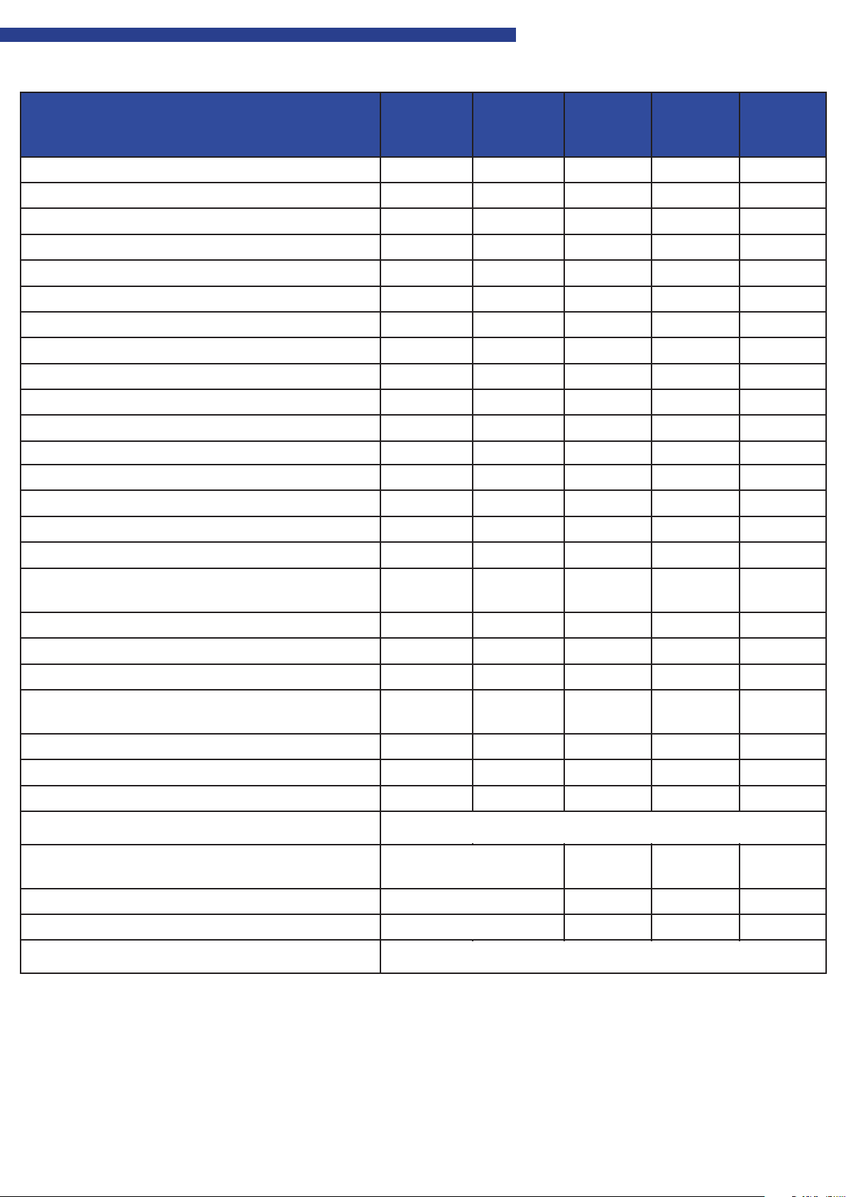
MAINTENANCE OVERVIEW
To see more about each service interval, look further in the book
Maintenance overview Daily Weekly After 250
working
hours
Each
500
hours
Each
750
hours
Cleaning the machine √
Visual inspection of tyres √
Check fuel level, refuel if necessary √
Check the fan belt √
Check the conveyor rubber mat tension √
Engine service due to supplier´s regulations √
Check oil level in engine, add if necessary √
Check coolant level, add if necessary √
Draining water separator √
Change of oil in air lter (cyclone lter) √
Check the brushes, change if necessary √
Re-tighten elevator rake nuts √
Cleaning of water lter √ √ √
Check water nozzles, clean if necessary √ √ √ √
Lubrication due to lubrication scheme √ √ √ √ √
Cleaning of air cleaner element (clean plastic tank) √ √ √ √ √
Cleaning of radiator, blow with compressed air
only if necessary √ √ √ √ √
Check hydraulic oil level, add if necessary √ √ √ √
Replacement of hydraulic lter cartridge √
Replacement of hydraulic breathing lter √ √ √
Check for leakage on cooler and cooler hoses,
defect or porous hoses are to be changed out √ √ √
Check tension of elevator belts √ √ √
Check wheel bearings on wheel axle √ √ √
Function control √ √ √
Recharging of battery
Visual inspection of oil leakage on hydraulic
system, tighten if necessary √ √ √
Check wheel nuts, tighten if necessary (460 Nm) √ √ √
Check pressure in tyres (675 kPa) √ √ √
Replacement of hydraulic oil
Aer instruction
Aer instruction
Aer instruction
Every two years
If necessary

8www.broddson.com
WARRANTY
Broddson provides a 12-month factory warranty on each new machine.
The warranty applies to material defects and incorrect work up to a maximum of 1000 operating
hours and provided that the prescribed service and maintenance have been performed.
Broddson assumes all costs if a design defect is found. Otherwise only compensation is paid
wrong part and shipping in one direction.
Please always mention the machine type, year model and production number.
This information is indicated on the nameplate.

9www.broddson.com
MAIN DIMENSIONS FRONT AND REAR VIEW

10 www.broddson.com
1. Conveyor
2. Elevator
3. Dydraulic valve
4. Side door
5. Dieseltank
6. Engine
7. Hydraulic pump
8. Hydraulic oil tank
9. Drawbar
10. Towing eye
11. Sprinkler system
12. Water Pump
13. String collectors
14. Side brush suspension
15. Side brushes
16. Chassis
17. Water tank
18. Rear Wheel
19. Roller brush suspension
20. Roller brush
21. Collector shoe
MAIN DIMENSIONS SIDE VIEW

11 www.broddson.com
REQUIREMENTS ON THE TRAILER VEHICLE
The towing truck which should be a truck with tipper body, it must be equipped with the following:
- rotating warning lights
- adapted towing device
- connector for connecting lighting, brake and turn signal to the sweeper.
When connecting the sweeper to the towing vehicle, the drawbar
shall be adjusted so that it is horizontal between the truck and
the sweeper.Height adjustment is done by
changing the drawbar, attaching (A).
The control panel is easily visible in the driver’s cab and within easy reach of the driver.
The supplied plug socket for remote control shall be mounted rmly on the rear of the towing
vehicle in connection with the towing device.
A

12 www.broddson.com
RECOGNITION OF SIGNS AND SIGNALS
NOTE!
Always read the instruction manual!
The sticker is placed on
electrical box inside the door
NOTE!
Maximum hydraulic pressure!
The sticker is located on the right
side cover
WARNING!
Do not stand between the truck and the
machine during connection,
Severe crush injuries can occur
Decal is placed on the drawbar.
WARNING!
For rotating brushes, 3 decals are placed in
the following places: the tailgate for the roller
brush, and on the side doors.
WARNING!
Serious personal or property damage can occur if the warning instructions are
not followed.

13 www.broddson.com
WARNING!
To prevent freezing (below 0 °
• Empty the water tanks.
• Empty the water lter on water (D).
• Start the machine operation, switch on the water system.
Run the water until it runs out. Then shut down the operation
• Follow the steps below.
• Start machine operation and switch on water distribution.
Run the system until ushing uid comes from the water nozzles.
• Fill the container with ushing liquid
( not concentrated! ).
• The container holds about 7 liters.
• Turn the crane (A) Clockwise until it is at the botom.
(Closed position)
• After the frost protection, this tap is used to set
the water pressure, which should be MAXIUM
6 BAR!
A
ANTIFREEZE SYSTEM

14 www.broddson.com
• The picture on the left shows how the cranes
• relationship stands when to sweep and
• use the water system.
• The picture on the left shows how the cranes
relationship stands when to protect against
frost.
• (B) Shows that the faucet for the antifreeze
container is open.
• (C) Shows that the main tap for the water is
closed.
B
C
D
ANTIFREEZE SYSTEM

15 www.broddson.com
- Back to the towing vehicle
- connect the towing vehicle, Make sure it does not tilt more than 5 degrees in relation to the truck’s
- Lower the parking support (B), to the right height through the knob (A).
- Connect the lighting connector
- Connect remote control box
- For sweepers equipped with air brakes. connect air connection to the truck’s braking system
- Attach both rubber straps (D) from the conveyor on each side of the atbed.
- Release the handbrake by cranking the handbrake (C) counterclockwise until the brake is released.
- For sweepers equipped with air brake, the actuating valve must also be pressed in to release the brake.
D
A
B
C
CONNECTING THE TOWING VEHICLE

16 www.broddson.com
A
B
D
Disconnection of the street sweeper
- Engage and block the parking brake by cranking the handle (A) clockwise until
the parking brake is completely blocked.
- Disconnect the electrical system by turning the key at the main switch (D) located on the
right front side of the street sweeper and remove the key.
- Remove the electrical socket for the lights.
- Remove the socket for the remote control.
- Remove the two rubber strings for the conveyor which are fastened at the sides of the tipper body.
- Lower the parking support jack to a proper position by turning the knob (B).
- Disconnect the towing eyelet from the towing truck.
DISCONNECTION OF THE SWEEPER

17 www.broddson.com
A
D
B
C
MANUAL LOWERING OF THE SWEEPING DEVICE
When the diesel engine is not running, side brushes, roller brush and elevator are lowered by tur-
ning the handle (A) on the ball valve 90 degrees to the right.
The crane is located inside the left side door next to the return crane from the left side brush motor
The oil then goes directly to the hydraulic oil tank and thereby lowers the sweep unit.
In order for the raising and lowering of the sweeper unit to work from the remote control again the
handle must (A) turned back parallel to the ball valve (D).
Position (B)is for maintenance of hydraulic hoses and couplings only. At this position, the return
line is bypassed and can cause major damage to the hydraulic system if it is not reset to that
position (C) before starting the machine.

18 www.broddson.com
Anchoring of the sweeper for transport
When transporting the sweeper on another vehicle
the machine must be xed on each side of the shaft,
in the mounting loops mounted on the chassis.
The anchoring points are marked out with
enclosed symbol.
LIFT OFF THE SWEEPER
When lifting the sweeper with, for example a crane.
Lifting cables must be attached to each side of the elevator,
in the lifting eye. The lifting wire should also be attached at the rear.
There markings are available.
Place for mounting of lifting cables is marked with
the symbol shown on the right

19 www.broddson.com
THE LOADS OF THE TRUCK
Warning! The towing vehicle must withstand loads as shown below:
R1S = static pressure – vertically
Service weight 4.300kg
Total weight 6.600kg
R1S = 850kg

20 www.broddson.com
FIRST HOURS OF OPERATION
IMPORTANT!
After the rst 8 operating hours, tighten the nuts holding the brush plate.
At the same time check the other screws and nuts at the brushes so that they are xed.
Also tighten the nuts that hold the elevator rakes in the belts.
The tightening torque shall be 10 Nm.
This should then be done regularly every 40 hours of operation.
After the rst 25 hours of operation, the following must be tightened:
- wheel bearing clearance
- wheel nuts
- hydraulic couplings
The sweeper must be continuously checked to maintain and
any consequential damage is prevented.
Table of contents
Popular Farm Equipment manuals by other brands

Harvest TEC
Harvest TEC 444T installation manual

P.Lindberg
P.Lindberg 9051583 Original manual

GREAT PLAINS
GREAT PLAINS Turbo Max VT1110-7.5M Operator's manual

Warn
Warn ProVantage 79958 installation instructions

Vicon
Vicon EXTRA 632 T Assembly instructions

GREAT PLAINS
GREAT PLAINS 2 Series Operator's manual

Amazone
Amazone Cayros Series operating manual

KUHN
KUHN GF7001 T Operator's manual

Westeel
Westeel Bin on Hopper Pea Installation and Storage Instructions

Raven
Raven SmarTrax Spra-Coupe 220 installation manual

SlurryKat
SlurryKat Low-Line Series Operation and maintenance manual

Warn Industries
Warn Industries 80558 installation instructions