manuals.online logo
Brands
  1. Home
  2. •
  3. Brands
  4. •
  5. First
  6. •
  7. Control Unit
  8. •
  9. First 700 Series Instruction Manual

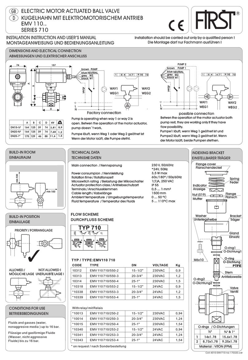
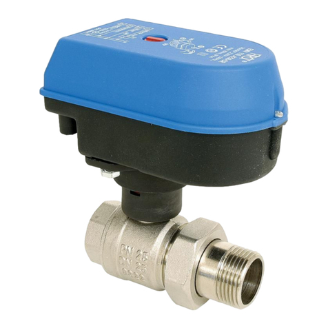
First 700 Series Instruction Manual

R
SERIES 700, 800, 801
157
D
A
CB
G
¾”
1"
DN
20
25
A
157
164
B
135
138
C
22.0
25.5
D
145
165
E
85
95
1.66
2.0
G
½"
¾”
1"
DN
15
20
25
A
148
157
164
B
130
135
138
C
17.5
22.0
25.5
D
63
74
88
1.0
1.15
1.4
G
½"
¾”
1"
DN
15
20
25
A
148
157
164
B
130
135
138
C
17.5
22.0
25.5
D
63
74
88
E
99
110
127
1.1
1.3
1.5
Series 700..
Series 800.. Series 801..
E
E
D
D
D
G1
min 100
min 100
1
2
14x1.78
8.73x1.78
15.6x1.78
9.25x1.78
½” ” & 1"
EMV 110..
ELECTRIC MOTOR ACTUATED BALL VALVE
KUGELHAHN MIT ELEKTROMOTORISCHEM ANTRIEB
GB
D
INSTALATION INSTRUCTION AND USER’S MANUAL
MONTAGEANWEISUNG UND BEDIENUNGSANLEITUNG
Installation should be carried out only by a qualified person !
Die Montage darf nur Fachmann ausführen !
DIMENSIONS AND ELECTICAL CONNECTION
ABMESSUNGEN UND ELEKTRISCHER ANSCHLUSS
BUILD-IN ROOM
EINBAURAUM
TECHNICAL DATA
TECHNISHE DATEN
Main connection ................... ........
Power consumption ............. .............................................
Rotation time......................... .................................................
Microswitch rating ............... ..........
Insullaton class .................... ......................
Actuator protection class .... ..............................................
Terminals............................... ..............................
Cable length.......................... ..................................................
Ambient temperature ........... ..............................
Humidity ................................ ....................
Fluid temperature.................
Nennspanung
Nennleistung
Rotationszeit
Belastung der Mikroschalter
Elektromotor isolationsklasse
Antreibsschutzart
Anschlussklemmen
Kabellänge
Umgebungstemperatur
Feucht
Temperatur des Fluids.......................
230VAC, 50Hz (EMV110..530)
*
3,5 W max
30s /90°
1(1)A, 250 VAC
F140°C
IP 55
0,5 ... 1 mm
1500 mm
0...50 °C
RH0% - 80% NON CONDESED
5...110°C max
24VAC, 50Hz (EMV110..533)
2
BUILD-IN POSITION
EINBAULAGE
PRIORITY / FORRANGLAGE
ALLOWED / MÖGLICHE LAGE
NOT ALLOWED !
UNERLAUBTE LAGE !
Fluids and gasses ( water,nonaggresive media ) up to 16 bar.
Flüssige und gasförmige Fluide ( Wasser, nicht aggressive Fluide ) bis zu 16 bar.
O-rings / O-Dichtungen
Valve
2 - EPDM
1 - EPDM
Ventil
Stem
M6x10
Gland
Einsatz
Unterlegsheibe Träger
Bracket
Washer
Flange
Indicator
Flange cover
Spring
Nut (S19)
Anzeige
Flansch
Mutter
Flanschendeckel
Feder
Antriebswelle
INDEXING BRACKET
EINSTELLBARER TRÄGER
CONDITIONS FOR USE
BETRIEBSBEDINGUNGEN
Brown
Blue
Grey OPEN
Black
Gr/ge
PUMP
NEUTRAL
L
N
v/g
CLOSE
Schw ZU
Grau AUF
Blau NEUTRAL
Braun PUMPE
kg
kg kg
Flow/pressure drop characteristic
Volumen Durchfluss und Druckabfall
2 - PTFE
1 - VITON
HYDRAULIC INSTALLATION: recomended instalation of the electric actuated ball valve
SCHEMA DER MASCHINENINSTALLATION: Empfohlener einbau des kugelventils mit elektromotorantrieb
1 manual stop valvel /
manuelles Absperrventil Kugelventil
2 strainer with the mesh width 0,65 mm /
Reinigungsfilter Y (für detaillierte
Informationen bitte rufen Sie uns an
lieferbar in Abmessungen von 1/2" bis 2”
3 motor actuated ball valve series
EMV 110...
Elektromotorantrieb mit Kugelventil
EMV 110…
IMPORTANT !
WICHTIG!
To extend the long term performance of the motorised ball valve it is recomended that
a strainer is situated prior to the valve. By installation must be observed to according to
relavant local standards.
Um die Lebensdauer des Ventil zu verlängern und Vernichtung der Dichtungen durch
mechanische Teile in der Installation zu verhindern wird der Einbau eines
Reinigungsfilters empfohlen. Die einschlägigen VDE+TÜV -
Verschriftensindzubeschten.
1 2 13
M
flow direction
Durchflußrichtung
Cx4-4010-EMV78NA-170236
1/2", 3/4", 1"

L
N
THERMOSTAT CONNECTION
ANSCHLUSS AUF DEM THERMOSTAT
PARRALLEL CONECTION
PARALLEL VERBINDUNG
POSITION VALVE INDICATOR
ZEIGER DER VENTILLAGE
INDIKATOR / ANZEIGE
Red - OPEN
Rot - AUF
1712
EMV 110..
L
N
1712
EMV 110..
+
RM24
1 2 3 4
L
N
1712
EMV 110..
+
RM24
EMV 110..
+
RM24
1 2 3 4
1712
1 2 3 4
L
N
1 1
7 7
12 12
EMV 110.. EMV 110..
NO !
NEIN ! O.K.
with a relay / mit Relais
without relay / ohne Relais
3-wire connection/3-Aderverbindung
switch over contact normal open (close) contact
2-wire connection/2-Aderverbindung
Arbeits (Ruhig) kontakt
anschaltung kontakt
RELAY MODULE BUILD-IN INSTRUCTION
RELAIS - EINBAUEN
1. Unscrew cower screws
2. Disconnect connection cord
3. Insert a relay module
4. Connect a relay module
according to scheme
5. Return the cover
Die Schrauben des Antriebdeckel
herausdrehen
Anschlusskabel abklemmen
Ralais Modul einsetzen
Relais Modul anschliessen
Antriebdeckel anschrauben
RELAY MODULE RM 24
RELAIS MODUL RM 24
ELECTRICAL SCHEME
ELEKTRISCHE STEUERSCHEME
with a relay / mit Relais
L1
N
yegr/grge
black/schw
Clo/zu
Open/auf
grey/grau
blue/blau
brown/braun
1 3 467910 12
1
24
1
2
4
M
POSITION EXCHANGE
LAGE VERWECHSLUNG
1. Depress the actuator towards
the valve
2. Rotate the actuator manually
3. The spring returns the actuator
and snaps it
Den Antrieb nach Ventil drücken
Den Antrieb drehen und
loslassen
Die Druckfeder bringt den
Antrieb wieder zurück und
schnappt in die eingestellte
Lage
1. open the cover
2. exchange wire connection
1 and 12, 4 and 9
das Gehäuse öffnen
die Auschlussader auf
Fessel 1 und 12 ,
4 und 9 wechseln
R
112
49
12
9
1
4
1. 2.
3.
1<-->12
4<-->9
L1
N
re/ro
1 2
3 4
1 3 4 6 7 910 12
CLOSE
/ZU
OPEN
/AUF
yg/gg
yegr/grge
bl/sch
grey/grau
bl/sch
blue/bl
blue/bl
br/br
br/br
1
24
1
2
4
M
MANUAL OPERATION
HANDSTEUERUNG
Den Antrieb nach Ventil drücken
Den Antrieb drehen
Die Druckfeder bringt den Antrieb
wieder zurück und schnappt in die
eingestellte Lage
1. depress the actuator towards the valve
2. rotate the actuator
3. the spring returns and snaps the
actuator
FOR AUTOMATIC MOTOR OPERATION, RETURN
THE ACTUATOR INTO IT,S ORIGINAL POSITION !
NACH HANDSTEUERUNG BRINGEN SIE DEN
ANTRIEB IN DIE ANFANGSLAGE ZURÜCK !
1.
2.
3.
Without relay / ohne Relais
FIRŠT-ROTOTEHNIKA, s.p., Radegunda 54, SI-3330 Mozirje,
tel: +386 3 898 35 00, fax:+386 3 898 35 35, e-mail:[email protected], http://www.first.si
SLOVENIJA
Data subject to change without notice. / Technische Änderungen vorbehalten.
Ord. code: RM 24 - 230VAC: 10024
RM_48ST/24VAC: 100049

This manual suits for next models

2

Other First Control Unit manuals

First 710 Series User manual

First

First 710 Series User manual

First EMV100 800 Series User manual

First

First EMV100 800 Series User manual

Popular Control Unit manuals by other brands

Thinklogical Q-Series product manual

Thinklogical

Thinklogical Q-Series product manual

Bubec UM2455 user manual

Bubec

Bubec UM2455 user manual

Purified Air UV-O 500 Technical and Operations Manual

Purified Air

Purified Air UV-O 500 Technical and Operations Manual

AquaScape 48026 Instructions & maintenance

AquaScape

AquaScape 48026 Instructions & maintenance

CONFLOW UNIWORLD Series Installation and maintenance manual

CONFLOW

CONFLOW UNIWORLD Series Installation and maintenance manual

Durapac RFJ Series instruction manual

Durapac

Durapac RFJ Series instruction manual

Trenz Electronic TE0720 Schematics

Trenz Electronic

Trenz Electronic TE0720 Schematics

NI PXIe-4304 CALIBRATION PROCEDURE

NI

NI PXIe-4304 CALIBRATION PROCEDURE

Honeywell Braukmann FD300 installation instructions

Honeywell

Honeywell Braukmann FD300 installation instructions

Ross RSe Series operating instructions

Ross

Ross RSe Series operating instructions

Warren rupp Sandpiper HDB1 1/2 Service & operating manual

Warren rupp

Warren rupp Sandpiper HDB1 1/2 Service & operating manual

SMC Networks EX260 Series Operation manual

SMC Networks

SMC Networks EX260 Series Operation manual

Jetter JM-200-ETH user manual

Jetter

Jetter JM-200-ETH user manual

Infineon PressFIT Assembly instructions

Infineon

Infineon PressFIT Assembly instructions

Goetze 851 Assembly and maintenance instructions

Goetze

Goetze 851 Assembly and maintenance instructions

Symmons Temptrol 262XBODY installation instructions

Symmons

Symmons Temptrol 262XBODY installation instructions

Tunstall Macon STV Series manual

Tunstall

Tunstall Macon STV Series manual

Princess auto PRO POINT 8688863 manual

Princess auto

Princess auto PRO POINT 8688863 manual

manuals.online logo
manuals.online logoBrands
  • About & Mission
  • Contact us
  • Privacy Policy
  • Terms and Conditions

Copyright 2025 Manuals.Online. All Rights Reserved.