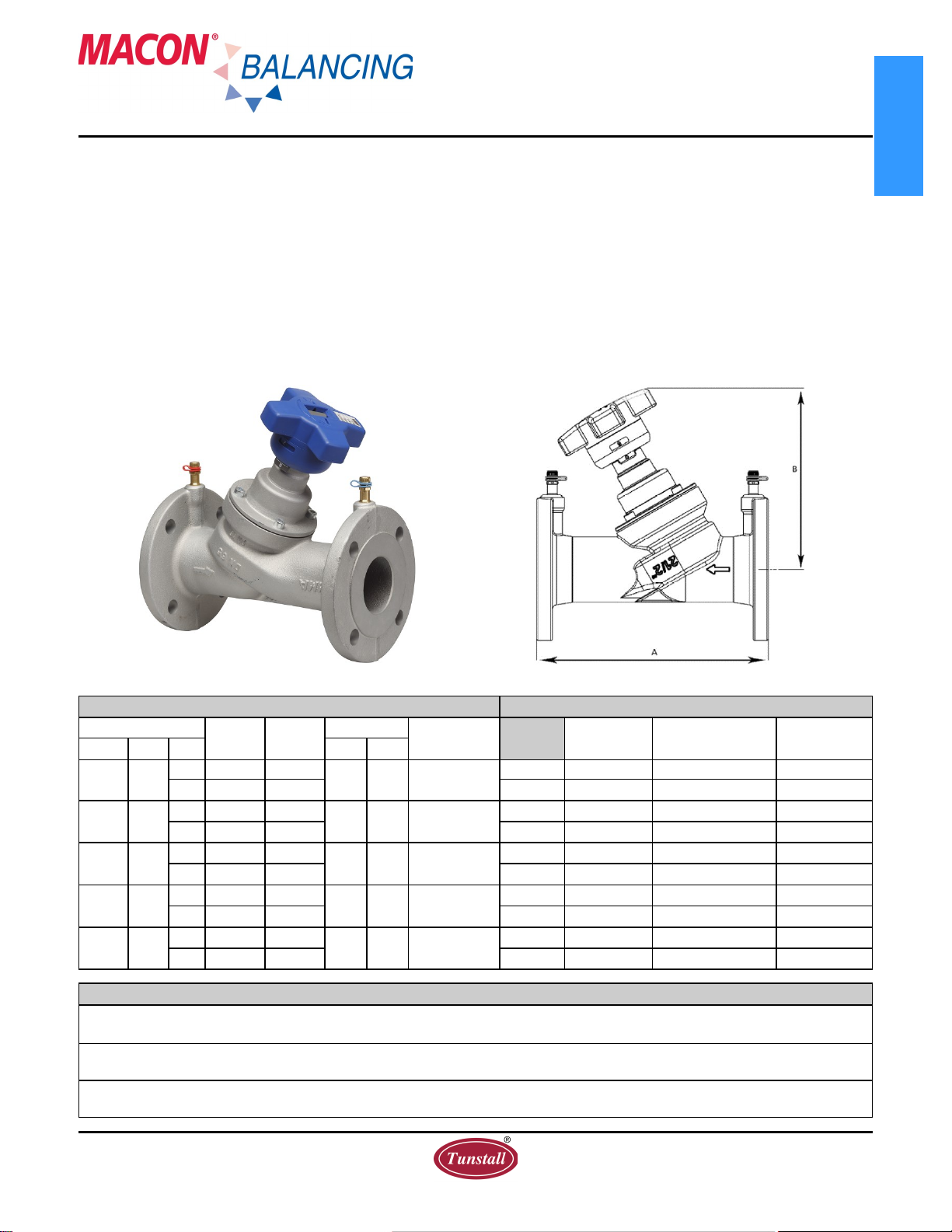
Pressure Drop Tables
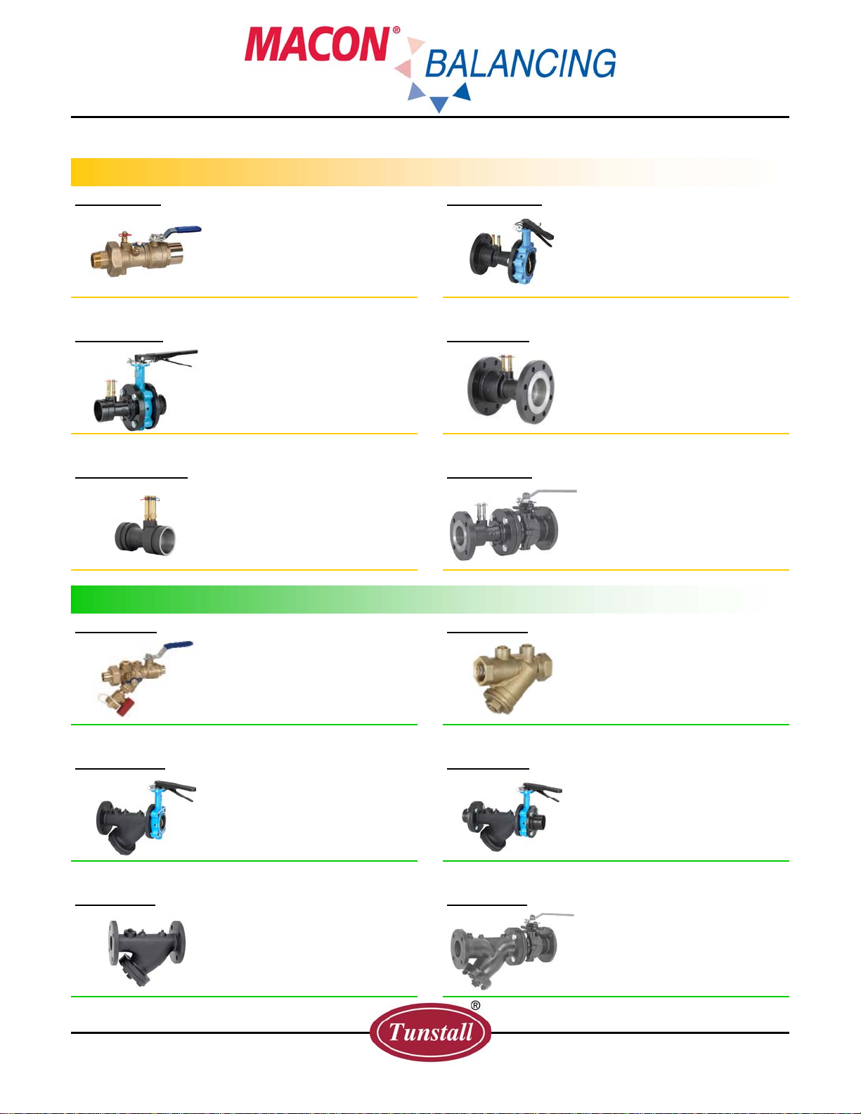
- Series LL-STV / LL-STVL
Optional features and accessories available for this
Macon product are an extra charge, and not included
in the standard model price.
www.maconbalancing.com
Tunstall Corporation
118 Exchange Street · Chicopee, MA 01013
Phone (413) 594-8695 · Fax (413) 598-8109
Section: Components Bulletin-MB-LL-STV-STVL-0915
Cv Values for Valve Series LL-STV / LL-STVL
1 0.21 0.39 0.56 0.92 1.39 2.32
1.5 0.29 0.56 0.75 1.28 1.97 3.25
2 0.37 0.70 0.89 1.53 2.38 4.18
2.5 0.44 0.82 1.04 1.80 2.78 5.10
3 0.52 0.96 1.19 2.09 3.25 6.03
3.2 0.56 1.02 1.28 2.26 3.48 6.50
3.4 0.59 1.09 1.39 2.44 3.71 6.96
3.6 0.63 1.16 1.51 2.67 4.06 7.54
3.8 0.67 1.23 1.62 2.90 4.41 8.12
4 0.72 1.31 1.74 3.13 4.76 8.82
4.2 0.77 1.39 1.91 3.42 5.10 9.74
4.4 0.81 1.48 2.09 3.71 5.57 10.70
4.6 0.87 1.58 2.26 4.06 6.03 11.70
4.8 0.93 1.68 2.44 4.41 6.61 12.80
5 1.00 1.80 2.67 4.76 7.19 13.80
5.2 1.07 1.91 2.90 5.16 7.77 15.00
5.4 1.14 2.03 3.19 5.57 8.35 16.00
5.6 1.21 2.16 3.48 5.97 8.93 17.20
5.8 1.28 2.30 3.83 6.38 9.63 18.30
6 1.36 2.44 4.18 6.84 10.30 19.40
6.2 1.44 2.60 4.47 7.25 11.00 20.40
6.4 1.52 2.76 4.76 7.66 11.80 21.50
6.6 1.62 2.96 5.10 8.12 12.50 22.50
6.8 1.74 3.16 5.54 8.58 13.20 23.50
7 1.88 3.36 5.80 9.05 13.90 24.60
7.2 2.06 3.60 6.15 9.51 14.60 25.50
7.4 2.26 3.83 6.50 9.98 15.30 26.40
7.6 2.49 4.06 6.84 10.40 15.90 27.40
7.8 2.73 4.27 7.19 10.80 16.50 28.20
8 2.96 4.47 7.54 11.30 17.10 29.00
8.2 3.13 4.63 7.89 11.70 17.60 29.90
8.4 3.29 4.78 8.24 12.20 18.20 30.70
8.6 3.42 4.93 8.58 12.60 18.80 31.60
8.8 3.54 5.08 8.87 13.00 19.40 32.40
9 3.65 5.22 9.16 13.30 19.80 33.20
9.2 3.77 5.36 9.40 13.70 20.30 33.90
9.4 3.87 5.50 9.63 14.20 20.90 34.60
9.6 3.98 5.64 9.86 14.50 21.50 35.30
9.8 4.06 5.78 10.00 14.80 22.00 36.00
10 4.12* 5.92* 10.2* 15.2* 22.6* 36.5*
* Valve is fully open
Flow coefficient values (CV's) at various handwheel settings
Series LL-STV &
LL-STVL 1/2” - 2”
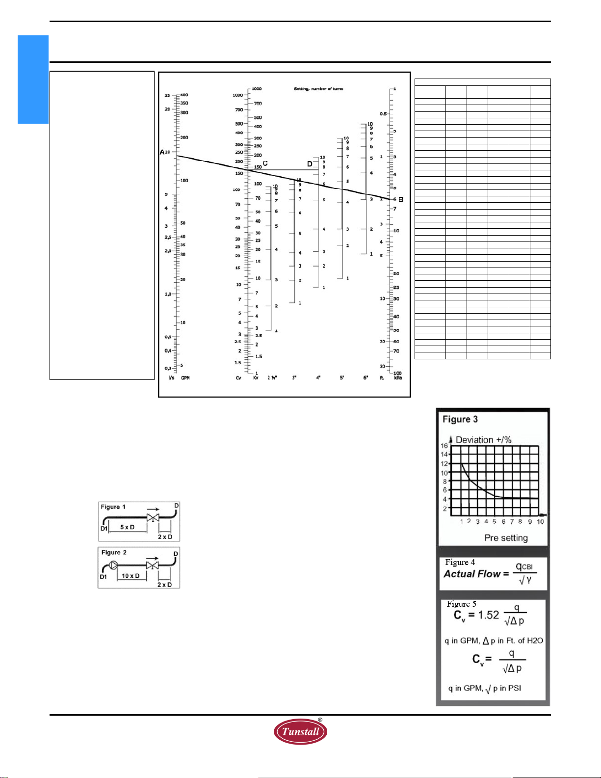
This diagram details the
relationship between flow,
pressure drop and valve
preset points. Use the dia-
gram to select the correct
valve size and corresponding
handwheel setting to fulfill
the application requirements.
Determine the required flow
in the circuit (A) and the
pressure drop (B). Draw a
line between these two val-
ues. Read off the corre-
sponding Cv value on the Cv
scale.
Determine the valve setting,
in handwheel turns, by draw-
ing a horizontal line (D)
from the intersection point
on the Cv scale to the corre-
sponding valve setting posi-
tion.
For the highest level of accu-
racy, it is recommended to
choose a valve that has at
least 3 open turns.
Example: A 1” valve is
required to be open 8 turns for
a Cv value of 7.5 at a flow rate
of 10 gpm and a pressure drop of 4ft.
Installation Recommendations
Install the valve in the correct flow direction
according to the arrow on the valve body and the
distance parameters detailed in Figure 1.
(Note: D = pipe diameter).
For Series LL-STVL, cover the valve body with a wet
cloth when soldering to prevent premature deteriora-
tion of valve components.
When used with a pump, it is recommended to use a
straight length of pipe totaling 10 x D (instead of 5 x
D) upstream or downstream to avoid turbulence that
will affect the measuring accuracy. See Figure 2.
Turbulence can influence the measurements by up to
20% if this recommendation is not followed.
Flow Measurement & Accuracy
The measuring instrument connects to the test ports of
the valve and is pre-programmed with Macon Balanc-
ing characteristics. The pressure drop and flow read-
ings can be read off the display. If access to a Macon
Balancing instrument is unavailable, other industry
models are compatible. In addition, the flow can be
determined using the pressure drop diagram that is
included in the operating instructions with each
Macon Balancing valve.
The accuracy is highest when the valve is fully open.
Therefore, it is recommended to choose a valve that
can be opened at least three turns at the calculated
pre-setting value. Figure 3 represents the flow
measurement deviation in relation to handwheel turns.
Correction for Liquids
Applies to liquids other than water. Correct the meas-
ured flow (q) by the density (Y) according to this
formula. See Figure 4.
Sizing a Balancing Valve
When the differential pressure and design flow are
known, use this formula to calculate Cv value.
See Figure 5.
Memory Stop
1. Set valves to desired position.
2. Turn the inner stem with a 3 mm Allen wrench
in a clockwise direction until it stops.
CIRCUIT
SETTER LOW LEAD