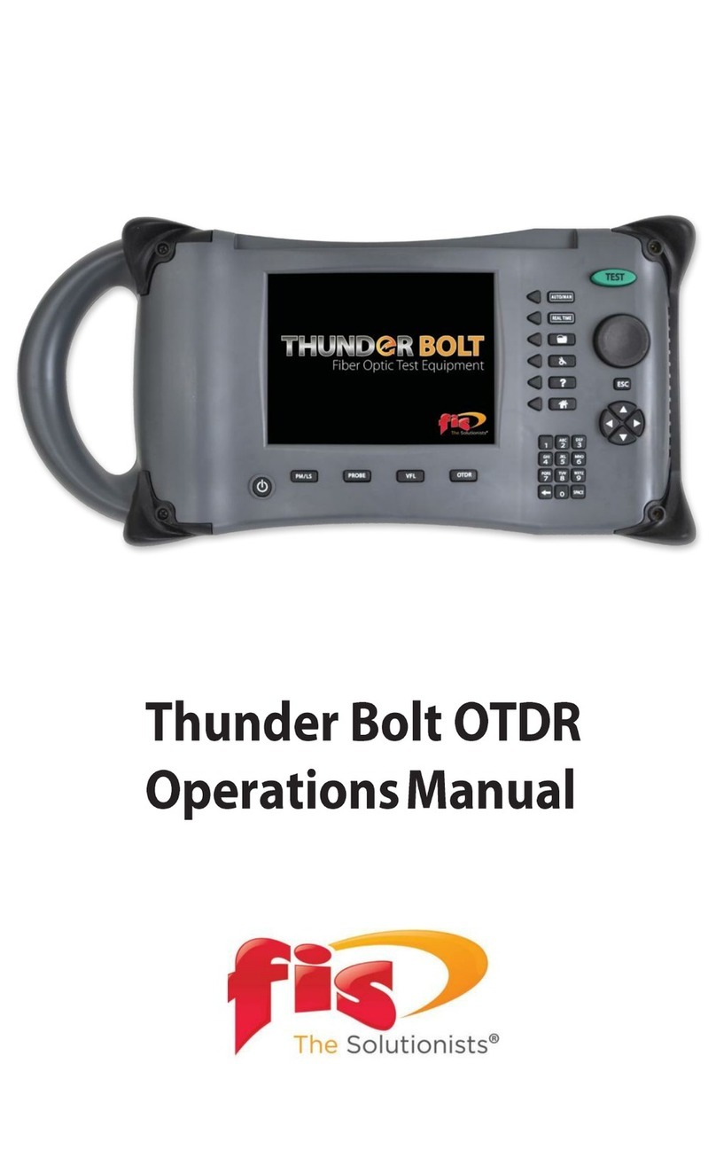
FIS OSR-CWDM User manual

Revision A
1/2019
OSR-CWDM Channel Analyzer
Users Guide
© 1/2019 Fiber Instrument Sales Inc.
Fiber Instrument Sales Inc. makes every eort to insure all statements and information for the products referred to in this docu-
ment are accurate and reliable. FIS can not accept any responsibility for errors, omissions or miss statements, nor can they ac-
cept responsibility for any actions taken based on the information demonstrated herein. FIS reserves the right to make changes
of any kind to the product referred to in this document without prior notice.

I
1. Using This Manual………..…………................................….........…………….......……………………………1
2. Safey………..……………......................................................……….……….......…………………...…………2
3. Quick Start Guide..……………….............................................….….…..........................……….……………4
4. Introduction ………….........…….....................................…..………….………………...……….……………..6
5. Preparation for Use ………....…...............................………….…………………………………………...……7
5.1 Inspection
5.2 Identication and Conguration
5.3 Power Requirements
6. Description……………......……….……….…...................................…….………......….....……..…………….8
Front Panel
Top Plate
7. User Interface................................................ ……..............................….....…..……...……….….......….…..9
7.1 Keypad
7.2 Graph Display
7.3 Menu
Display with Menu Open
Icon Descriptions
Help
Bar Graph View
File Management
Settings
Scope
8. Setting Test Parameters…..…………………………......................................…............…………………..…12
8.1 Parameter Settings Screen
8.2 Setting Parameters
View Setting
Measure
Brightness
Pass Range
Table of Contents
Section PAGE

9. Operation..............................………………………………………………......………........…………...………14
9.1 Start-Up
9.2 Connecting Fiber
9.3 Taking Scans
Scanning
Using Stored Congurations
9.4 Viewing Scans
Graph Display
Graph Information
dBm Scale
Channel Scale
Channel Pass Zone
Cursor Data Information
“A” to “B” Cursor Relational Data
Total Power/Tilt Measurements
9.5 Cursor Operation
Set Active Cursor
Cursor Movement
10. File Management …………….…………………………………………….......……..............………………....17
10.1 File Management Display
Main File Management Screen
Conguration and Scope Folder Displays
10.2 Saving Files
Saving Channel Analyzer Files
Saving Scope Files
Saving Congurations
10.3 File Operations
Making Files for Batch Operations
Deleting Files
Rename Files
Compare Files
Upload Files
Section PAGE
II
Table of Contents
(Continued)

11. Video Scope Operation……................................………………..………....................……………………… 20
11.1 Video Scope Display
11.2 Video Scope File/Help Menu
Home
Quick Save
Quick Load
File Management
Help
11.3 Video Scope Operation Menu
Grading Rings Icon
Pass/Fail Label Icon
Brightness Icon
11.4 Video Scope Operation
Video Probe Tips
Viewing/Focusing a Connector
Centering a Connector Image
Pausing Image Scan
Grading Rings
Pass/Fail
Marking Point of Contamination
Exiting Video Scope Operation
11.5 Pass/Fail Contamination Tables
12 Maintenance ……………………………………………….………..………....................……………………… 25
12.1 Battery Replacement.
12.2 Calibration and Verication
12.3 Adapter Replacement
13. Specications …………………….………….……………………..….……..….............………………………..26
14. Warranty and Repair……………………….………….………………….........….......................……....……...27
14.1 Warranty Information
14.2 Repair Information
15. Trouble Shooting..……….….…………….…………………………............……..............………....................28
16. Version Control………….….…………….…………………………...........……..............………..….…….…..29
III
Section PAGE
Table of Contents
(Continued)

OSR-CWDM Users Guide Revision A 1/2019 1
This Manual contains information for the OSR-CWDM Channel Analyzer. This equipment is touch
screen capable and also has a hard keypad for operation. Note that there are a few operations that
are only accessible with touch screen operation.
This user’s guide is written primarily using the touch screen operation with occasional mention of the
hard key equivalents
There are warnings, cautions and notes as described below displayed throughout this manual. Please
follow all warnings and cautions for your safety and the protection of the equipment.
Warning
A warning alerts to situations that could cause personal injury.
Caution
A caution alerts to situations that may cause damage to the equipment or produce poor testing
conditions resulting in inaccurate test results.
Note
A special annotation that will assist the user with operational features.
Section 1 Using This Manual

2OSR-CWDM Users Guide Revision A 1/2019
This product has been designed and tested in accordance with the Manufacturer’s safety standards, and has
been supplied in a safe condition.
Below are warnings that must be followed by the user to ensure safe operation and to maintain the product in
a safe condition. Failure to follow these safety warnings, can result in damage to the instrument or harm to the
user.
Warning
Personnel should always be aware when working with ber optic test equipment that active
bers may be present and therefore infrared optical energy may be present.
Warning
Never look directly into the end of a connected ber optic cable or ber optic adapter of test
equipment, to do so could expose the user to laser radiation and could result in sever personal
injury.
Warning
To Prevent Fire or Shock Hazard:
Section 3 of this manual is a quick start guide. Prior to using the quick start guide or operating
the equipment in any way, it is highly suggested the user reads all safety information.
Section 2 Safety
Do not install battery types other than those specied by the manufacturer¾
Do not use the charger without the batteries installed ¾
Do not expose the battery charger to rain or excessive moisture¾
Do not use the AC adapter when there are signs of damage to the enclosure or cord¾
Ensure that you are using the correct charger for the local line voltage ¾
Do not use any other charger than the one provided with this instrument.¾

3OSR-CWDM Users Guide Revision A 1/2019
Failure to follow these cautions may damage the equipment and void the warranty.
Caution
The OSR-CWDM is designed for maximum power of +5 dBm per channel and a maximum com-
posite power of +23dBm.
Caution
Fiber-optic connectors are easily contaminated or damaged. The connection to the OSR-
CWDM is a physical contact type of connection and dirty or damaged connectors may impair the
instruments capabilities at minimum and at worst result in the need to return the OSR-CWDM
to the factory for expensive repairs. Prior to making any connection to the unit, ensure that all
proper cleaning procedures have been followed.
Use UPC Finish Connectors Only!
Section 2 Safety

4OSR-CWDM Users Guide Revision A 1/2019
Quick Start Guide
Press to turn on the OSR-CWDM
Caution
Fiber-optic connectors are easily contaminated or damaged. The connection to the OSR-
CWDM is a physical contact type of connection and dirty or damaged connectors may impair the
instruments capabilities at minimum and at worst result in the need to return the OSR-CWDM
to the factory for expensive repairs. Prior to making any connection to the unit, ensure that all
proper cleaning procedures have been followed.
Use UPC Finish Connectors Only!
Section 3 Quick Start Guide
Menu
To enter menu, either press the button or use the stylus to pull the menu up from the bottom of the
screen.
Available icons:
Help displays an on board explanation of features, functions and operations.
Bar graph, touching this icon returns the user to the bar graph.
File icon, touching this icon will brings the user to the le management menu.
Settings icon, touching this icon brings the user to the OSA and general settings menus.
Scope icon, this will opens the video scope feature.
Note
Most features of the OSR-CWDM are accessible with either the touch screen or the hard
buttons on the keypad. This quick start will primarily focus on the touch screen.

5OSR-CWDM Users Guide Revision A 1/2019
Attached the ber to be tested to the optical port.
Scan
Touch the scan indicator or the scan button on the keypad to start the scan.
To stop a scan, touch the scan indicator or press the scan button again.
Cursor Movement/Selection:
To move the cursors touch the screen and the active cursor will snap to that location and moving the stylus up or
down on the display will drag the cursor as desired.
To change the active cursor, touch the red or blue cursor points on the right side of the display. The one outlined
in black is the active cursor. (A/B button on the keypad)
Section 3 Quick Start Guide
Please review the remainder of this user’s guide for full instructions on
using the OSR-CWDM Channel Analyzer
Caution
The OSR-CWDM is designed for maximum power of +5 dBm per channel and a maximum com-
posite power of +23dBm.

6OSR-CWDM Users Guide Revision A 1/2019
The Fiber Instrument Sales Inc., OSR-CWDM Channel Analyzer oers full featured analysis of CWDM
systems in a hand held portable package. CWDM optical levels in CWDM Network, wavelengths
1271nm to 1611nm, may be measured with a resolution of 0.01 dB resolution from -50 to +5 dBm. This
unit has super fast acquisition time of two scans per second. There is a pass/fail feature to assist with
quick evaluation of the scan on the 4 inch color TFT Display. The OSR-CWDM is designed with solid
state optics and no fragile or moving parts to keep the unit eld friendly. There is storage for up to 1000
tests and the test may be viewed and printed with the included CertSoft software for fast and easy
reporting. These units are housed in a rugged enclosure with robust protective boot, are designed to
withstand the rigors of eld use and are extremely user friendly.
Section 4 Introduction

7OSR-CWDM Users Guide Revision A 1/2019
Before shipment, this instrument was inspected and found to be in perfect working order and free of defects.
The shipping carton contains the following:
1. Channel Analyzer, with protective boot and Li-ion battery installed
2. Universal AC/DC charger with interchangeable mains
3. USB cable
4. CD with CertSoft software and user’s manual
5. Set of interchangeable adapters, SC and FC
Section 5 Preparation For Use
5.1 Inspection
Fig 5.1
The instrument’s Model/Part Number, Serial Number and Date of Manufacture are indicated on a label located on
the back of the unit. The instrument’s history is led at the factory by model/part number and serial number. The
unit's serial number is also located on the top plate just above the USB Port.
5.2 Identication and Conguration
The OSR-CWDM is equipped with a 100-240V-0.4A input and 15V, 1.28A, center positive output universal AC/DC
battery charger. This charger is supplied with interchangeable mains for US, Great Britain, Europe and Australia.
The unit is shipped with factory installed Li-ion batter installed. Depending on usage, fully charged battery pack
will typically enable approximately 12 hrs. of use. Fully discharged batteries require approx. 2 hours to charge.
Batteries ar not eld replaceable and therefore the unit is to be returned to the factory for battery replaement.
Warning
To Prevent Fire or Shock Hazard:
Do not install battery types other than those specied by the manufacturer¾
Do not expose the battery charger to rain or excessive moisture¾
Do not use the AC adapter when there are signs of damage to the enclosure or cord¾
Ensure that you are using the correct charger for the local line voltage ¾
Do not use any other charger than the one provided with this instrument.¾
Failure to follow these caution statements may void the warranty of this equipment.
5.4 Power Requirements

8OSR-CWDM Users Guide Revision A 1/2019
The Channel Analyzer is packaged in a rugged housing which is further protected with a rubberized boot.
Although the front panel is weather resistant, care must be taken to avoid liquids and contaminants around the
fragile optical and electrical connectors, and the glass display. Use a mild cleaning agent and damp soft cloth to
clean up the panels and the outside case. See the maintenance section for notes to clean the optical connector.
NEVER open the instrument for cleaning. Return to the factory for servicing if necessary.
Section 6 Physical Description
Front Panel
Color Touch
Display
Key Pad
Fig 6.1
Protective Rubber
Boot
Top Plate
Optical Port
Fig 6.2
Video Probe Port
USB PC
Port
External Power Port
Charge Indicator

9OSR-CWDM Users Guide Revision A 1/2019
Section 7 User Interface
7.1 Keypad
Fig 7.1
Keypad
Power button turns the unit On and O.
(Hold for 1 second)
Scan button starts or stops a scan.
Not active
Not active
Toggles the menu open and closed on the bottom of the display
Toggles between “A” and “B” as the active cursors.
Active in the menu mode. Used to make selections of highlighted items.
LRUD (Left-Right-Up-Down) buttons to are used to move the active cursor in scan mode and move through
menu selections in menu mode.

10 OSR-CWDM Users Guide Revision A 1/2019
Section 7 User Interface
7.2 Graph Display
Touch anywhere in the bottom
three rows left of the battery
and scan indicators to open
the menu
Touch the last column in
the graph to toggles be-
tween A and B cursors
The area around the
scan activity indicator
toggles the scan mode
on and o
Fig 7.2
Touch anywhere in the main
graph area to move the active
cursor
7.3 Menu
Fig 7.3
Menu
Highlighted Icon

11OSR-CWDM Users Guide Revision A 1/2019
Movement between screens and functions is accomplished through a set of icons located in a menu that is
accessed by touching the bottom of the display or pressing menu button. To remove the menu from the bottom of
the display, either select an icon, touch the display above the menu or press the menu button.
To use the Menu, touch to the left or right of the highlighted icon in the center to move the icons left or right. The
left and right key pad buttons may also be used to move the icons. With the desired icon highlighted, touch it or
press the select button.
Below is a list of the icons found in the menu with a brief description of each.
Icon Descriptions
Help Help displays an on board explanation of features, functions and operations.
Bar Graph View Touching this icon returns the user to the bar graph.
File Mgt. File icon, touching this icon will brings the user to the le management menu.
Settings Settings icon, touching this icon brings the user to the OSA and general settings
menus.
Scope Scope icon, this will opens the video scope feature.
Section 7 User Interface

12 OSR-CWDM Users Guide Revision A 1/2019
Note
The directional buttons and the select button are not operational in the settings screen.
The View, Measure and Brightness settings are toggles and when touched, will switch between options. The
Pass Range setting requires the user to enter a range for the dB Scale.
Section 8 Setting Test Parameters
Fig 8.1
Return to
Scan Mode
or File Manager
View -
Select between total
power and power tilt
modes
Brightness -
Chose either high or low
brightness
Measure -
Select between
measurments
displayed in wave-
length (nm) or
Frequency (Tz)
Pass Range -
Allows the user
to enter values to
display channels as
passing or failing
Note
The value in black is the current value, touching anywhere in the parameter box will change values.
8.1 Parameters Setting Screen

13OSR-CWDM Users Guide Revision A 1/2019
Section 8 Setting Test Parameters
View Setting
Ther are two power setting that may be diplayed for the scan. Total Power and Power Tilt, to select either of
these setting, simply touch the View setting box on the setting screen to toggle between the options. the black
value is the active value.
Total Power
Total power is the power being introduced to the ber. This value is shown in the bottom right cell of the display.
Power Tilt
Power Tilt, is displayed as a linear regression line overlaid on the graph and as a numeric indicator in the bottom
right of the display. This reading only factors in the channels that are greater than the minimum power level of the
scale. This can be used to assist with balancing the power of CWDM system. The atter (more level) the line, or
the closer to zero the power tilt number the more balanced the power between channels.
Measure
Depending on the system, channels my be listed in wavelength or frequency. The channel may be displayed in
wavelength (nm) or frequency (Tz) in the test date section at the bottom of the display. To change these settings,
pull up the menu and touch the settings icon. Touch the Measure setting to toggle between the two options.
Brightness
Depending on working conditions, a lower level of light may be best for optimal viewing of this equipment. Use
this brightness setting to toggle between low and high settings. To set the brightness level, enter the settings
screen by bringing up the menu and touching the settings icon. Touch the brightness section to toggle between
the two settings.
Pass Range
For a quick indication of passing channels, the pass range may be set to highlight the power level on the display
for a passing channel. Set this range so that channels meeting the passing criteria, fall into the green shaded
area of the dBm scale. To set the pass range, enter the settings screen by bringing up the menu and touching
the settings icon. Touch Pass Range section of the page.
When touched, there will be displayed a message to “Enter Minimum Power” and then the display will switch
to the the on screen QWERTY and the user can enter the desired value for the minimum passing value. Once
entered touch Save and the message “Enter Maximum Power” will be displayed and then switch again to the on
screen QWERTY. Enter the maximum pass/fail value and select save.
8.2 Setting Parameters

14 OSR-CWDM Users Guide Revision A 1/2019
Section 9 Operation Continued
9.1 Start-up
Press and hold the power button for one second to start the OSR-CWDM.
9.2 Connecting Fiber
Caution
The OSR-CWDM is designed for maximum power of +5 dBm per channel and a maximum com-
posite power of +23dBm.
Caution
Fiber-optic connectors are easily contaminated or damaged. The connection to the OSR-
CWDM is a physical contact type of connection and dirty or damaged connectors may impair the
instruments capabilities at minimum and at worst result in the need to return the OSR-CWDM
to the factory for expensive repairs. Prior to making any connection to the unit, ensure that all
proper cleaning procedures have been followed.
Use UPC Finish Connectors Only!
It is suggested that a test cable be used between the ber under test and the OSR-CWDM. This reference
ber should be approximately on meter in length and have minimal loss. The reference cable should be only be
removed from the unit when necessary. Limiting removal and termination of connectors to the unit will extend the
live span of the connector eliminating down time and costly repairs. Only UPC connectors are to be connected
to the OSR-CWDM.
Scanning
Once all the parameters have been set, the scan button may be press or the scan indicator may be used on the
touch screen to start a scan. Pressing the scan button or touching the scan indicator a second time will stop the
scan.
Using Stored Congurations
Test congurations are stored in the le management screen. To use a stored congurations, pull up the
menu and select the le management icon. Touch the Cong tab and from the le list, highlight the desired
conguration and press select on the keypad or touch the conguration name while highlighted. Scans will now
use the established parameters from the active conguration.
9.3 Taking Scans

15OSR-CWDM Users Guide Revision A 1/2019
Section 9 Operation Continued
Graph Information
dBm Scale
The dBm scale at the top of the display indicates -50 to +5 dBm.
Channel Scale
The channel scale displays the wavelength of the channels in the CWDM network. This scale will display the
available channel/wavelengths of the congured unit. The full scale for an 18 channel unit is is 1271-1611.
9.4 Viewing Scans
Graph Display
“A” Cursor Channel Power,
Wavelength/Frequency and Channel Number
“B” Cursor Channel Power,
Wavelength/Frequency and Channel Number
Power and Wavelength/Frequency Deviation
Between “A-B” Channels Total Power/Tilt Measurements
Wavelength Scale
dBm Scale
Channel Pass Zone
Fig 9.1
“A” Cursor
“B” Cursor

16 OSR-CWDM Users Guide Revision A 1/2019
Section 9 Operation
The “A” and “B” cursors may be moved with the touch screen or the up and down buttons on the keypad.
Set Active Cursor
The cursor to be moved must be set as the active cursor. This is indicated with a black outline around the cur-
sor point on the right side of the display. To set the active cursor, touch the desired cursor point with the stylus or
press the A/B button on the keypad to toggle between the cursors.
Cursor Movement
To move a cursor, touch anywhere between the channel number column and the cursor point column and the ac-
tive cursor will snap to the channel selected. To slide the cursor up and down on the display, touch the display and
slide the stylus up and down to drag the cursor to the desired position/channel number. The up and down buttons
on the keypad will move the cursors as well.
Channel Pass Zone
This green highlighted area of the display assist with quick evaluation of channels for pass/fail
state. Set this scale with the pass range setting on the settings screen.
Cursor Data Information
Channel power, wavelength/frequency and the channel numbers for selected channels are
displayed in the data section at the bottom of the display.
“A” to “B” Cursor Relational Data
The bottom row of the data section indicates the deviation of power between the “A” and “B”
cursors.
Total Power/Tilt Measurements
The total power or tilt information is displayed in the bottom right most cell of the OSA’s measurement table and
graph screen.
9.5 Cursor Operation
Table of contents
Other FIS Measuring Instrument manuals
Popular Measuring Instrument manuals by other brands
Siemens
Siemens DCA Vantage Operator's guide
Hanna Instruments
Hanna Instruments HI 9146 instruction manual

Bosch
Bosch BEA 070 Original instructions
Amprobe
Amprobe THWD-2 instruction manual
Siemens
Siemens SITRANS F M MAG 5000 operating instructions
RR Mechatronics
RR Mechatronics STARRSED TL Instructions for use
