GESTRA NRG 26-40 User manual

1
EN
English
Original Installation Instructions
810274-05
Level electrode
NRG 26-40

2
Contents
Page
Important notes
Usage for the intended purpose...............................................................................................................4
Function..................................................................................................................................................4
Safety note..............................................................................................................................................4
System components................................................................................................................................5
Directives and Standards
VdTÜV Bulletin "Wasserüberwachung 100" (= Water Monitoring 100).....................................................6
LV (Low Voltage) Directive and EMC (Electromagnetic Compatibility)........................................................6
ATEX (Hazardous Area) ............................................................................................................................6
UL/cUL (CSA) Approval ............................................................................................................................6
Note on the Declaration of Conformity / Manufacturer's Declaration ............................................6
Technical Data
NRG 26-40 ............................................................................................................................................7
Technical Data
Name plate/marking ...............................................................................................................................8
Scope of supply ....................................................................................................................................8
Installation
Dimensions NRG 26-40.........................................................................................................................10
NRG 26-40............................................................................................................................................11
Key .......................................................................................................................................................11
Tools.....................................................................................................................................................11
Examples of installation
NRG 26-40............................................................................................................................................12
Key .......................................................................................................................................................13

3
Contents - continued -
Page
Electrical connection
NRG 26-40............................................................................................................................................14
Key .......................................................................................................................................................14
Connection of level electrode ................................................................................................................15
Tools.....................................................................................................................................................15
Wiring diagram and pin assignments of connector / jack.......................................................................16
Key .......................................................................................................................................................16
CAN bus wiring diagram........................................................................................................................17
CAN bus voltage supply.........................................................................................................................18
Basic settings
Bus line.................................................................................................................................................18
Node ID.................................................................................................................................................19
Factory setting ......................................................................................................................................20
Establishing / changing node ID ............................................................................................................20
Code switch settings.............................................................................................................................21
Commissioning procedure
Applying supply voltage.........................................................................................................................22
Setting measuring range......................................................................................................................22
Operation
Setting the attenuation of the level signal..............................................................................................23
Troubleshooting
Indication, diagnosis and remedy ..........................................................................................................24
Further Notes
Action against high frequency interference............................................................................................25
Maintenance
Safety note............................................................................................................................................26
Cleaning the electrode rod ....................................................................................................................26
Removing and disposing of the level electrode
Removing and disposing of level electrode NRG 26-40..........................................................................26

4
Important notes
Usage for the intended purpose
The level electrode NRG 26-40 is used for continuous level monitoring in steam boilers and (pressur-
ized) hot-water installations or in condensate and feedwater tanks.
In conjunction with the level switch NRS 2-40 and the level controller NRR 2-40 the electrode can be
used for instance as water level controller with MIN/MAX alarm.
The level electrode is designed for use in conjunction with the following level switches/controllers:
NRS 2-40 and NRR 2-40.
The level electrode can be used in electrically conductive and non-conductive fluids.
Function
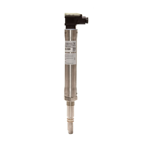
The level electrode NRG 26-40 consists of a level measuring electrode and an electronic module in
the terminal box.
The level electrode works according to the capacitance measurement principle and translates the level
changes into a data telegram, with the length of the electrode rod determining the measuring range.
The level electrode is installed inside steam boilers, vessels or in an external level pot. If the electrode
is installed inside the boiler or vessel, a protection tube provided on side ensures correct functioning
(see section Examples of installation (pages 12, 13).
The level electrode can be installed together with one GESTRA level electrode for water level limiting or
for high-level alarm in a single protection tube or external level pot.
At regular intervals the level electrode NRG 26-40 sends a data telegram to the control equipment
NRS 2-40 and NRR 2-40 or other system components. Data is transferred by means of a CAN bus
according to DIN ISO 11898 using the CANopen protocol.
Safety note
Danger
When loosening the level electrode steam or hot water might escape!
This presents the risk of severe scalding all over the body!
It is therefore essential not to dismantle the level electrode unless the boiler pressure is
verified to be 0 bar.
The level electrode becomes hot during operation.
Risk of severe burns to hands and arms.
Before carrying out installation and maintenance work make sure that the equipment is
cold.
The equipment must only be installed, wired and commissioned by qualified and competent staff.
Retrofitting and maintenance work must only be performed by qualified staff who - through adequate
training - have achieved a recognised level of competence.
5
Important notes
System components
NRS 2-40
Digital switching controller for level electrode NRG 26-40.
Functions: Four liquid levels with one switchpoint each, MAX alarm, MIN alarm, pump ON, pump OFF
with one switchpoint each, liquid level continuously within the predefined control band of the electrode.
Data exchange: CAN bus to ISO 11898 via CANopen protocol.
NRR 2-40
Digital switching controller for level electrode NRG 26-40.
Functions: Two level limits with one switchpoint each (high-level alarm, low-level alarm).
Three-position or modulating control within a predefined proportional band.
Water level monitoring within the defined control band of the electrode.
Data exchange: CAN bus to ISO 11898 via CANopen protocol. Two level limits with one switchpoint
each (high-level alarm, low-level alarm).
URB 1, URB 2
Operating & display unit.
Functions: Parameterization and visual indication via LCD display.
Data exchange: CAN bus to ISO 11898 via CANopen protocol.
Attention
The name plate specifies the technical features of the equipment. Do not commission or
operate any item of equipment that does not bear its specific name plate.
- continued -

6
For details on the conformity of our equipment with European Directives, please refer to our
Declaration of Conformity or our Manufacturer's Declaration.
The current Declaration of Conformity / Manufacturer's Declaration is available at
www.gestra.com Documents
, or can be requested from us.
Directives and Standards
VdTÜV Bulletin "Wasserüberwachung 100" (= Water Monitoring 100)
The level electrode NRG 26-40 in conjunction with the following control equipment is type approved
according to VdTÜV Bulletin "Wasserstand 100": NRS 2-40 and NRR 2-40.
The VdTÜV Bulletin "Wasserstand (=Water Level) 100" specifies the requirements made on water level
control and limiting equipment for boilers.
ATEX (Hazardous Area)
According to the European Directive 2014/34/EU the equipment must not be used in potentially
explosive areas.
Note on the Declaration of Conformity / Manufacturer's Declaration
LV (Low Voltage) Directive and EMC (Electromagnetic Compatibility)
The equipment meets the requirements of the Low Voltage Directive 2014/35/EU and the EMC
Directive 2014/30/EU.
UL/cUL (CSA) Approval
The equipment complies with the requirements of the following standards: UL 508 and CSA C22.2
No. 14-13, Standards for Industrial Control Equipment. File E243189.

7
NRG 26-40
Technical Data
Service pressure
PN 40, 32 bar at 238°C
Mechanical connection
NRGT 26-1: Screwed G ¾A, ISO 228
Materials of construction
Screw-in body: 1.4571, X6CrNiMoTi17-12-2
Electrode rod insulation: PTFE
Terminal box: 3.2161 G AlSi8Cu3
Length of installation
at 238°C
373 477 583 688 794 899 1004 1110
Measuring range 300 400 500 600 700 800 900 1000
Length of installation
at 238°C
1214 1319 1423 1528 1636 2156
Measuring range 1100 1200 1300 1400 1500 2000
Weight
approx. 2.5 kg
Electronic module
supply voltage
18–36 V DC)
Power consumption
65 mA
Fuse
Thermal fuse Tmax = 80°C
Hysteresis
-2 K
Data exchange
CAN bus to ISO 11898, CANopen protocol
Attenuation of signal output
19 seconds
Indicators and adjustors
1 10-pole code switch for node ID and baud rate setting
1 green LED "Communication CAN bus"
1 red LED "Malfunction in bus"
Electrical connection
M 12 sensor connector, 5 poles, A coded,
M 12 sensor jack, 5 poles, A coded
Protection
IP 65 to DIN EN 60529
Max. admissible ambient temperature
Max. 70 °C

8
Technical Data
Storage and transport temperature
– 40 to + 80 °C
Approvals:
TÜV certificate VdTÜV Bulletin "Water Level 100"
Requirements made on water level limiting & control equipment.
Type approval: TÜV · WR · XX-399 (see name plate)
NRG 26-40
Name plate/marking
Fig. 1
Manufacturer
Equipment designation,
Pressure rating, connection,
material number, protection
Pressure/temperature range
CAN bus data
Measuring range
CE marking
Safety note
Disposal note
Type approval no.
Scope of supply
NRG 26-40
1 Level electrode type NRG 26-40
1 Joint ring 27 x 32, form D, DIN 7603, 1.4301, bright annealed
1 Installation manual
Betriebsanleitung
beachten
See installation instructions
Hier öffnen
Open here
Ouvririci
Voir instructionsde
montage
18-36 VDC
Tamb = 70°C (158°F)
IN/OUT: CAN-Bus
Pmax
Tmax
NRG 26-40
PN40 G3/4 1.4571 IP65
32 bar (464psi)
238°C (460°F)
__ __ __
GESTRA AG
Münchener Str.77
D-28215 Bremen
TÜV ·WR·XX - 399
H= mm
Niveauelektrode
Level electrode
Électrode de niveau
- continued -
- continued -

9
Installation
Note
The level electrode NRG 26-40 can be installed together with one GESTRA level elec-
trode for water level limiting or for high-level alarm in a single protection tube or exter-
nal level pot (inside diameter 100 m). Fig. 5 - 8. If the level limiting electrode is installed
inside the vessel, it must be at least 40 mm away from the upper vent hole.
For the approval of the boiler standpipe the relevant regulations must be considered.
Refer to pages 12 – 13 for typical installation examples.
The angle of inclination of the electrode must not exceed 45°, with the length of the
electrode rod being limited to 688 mm. Fig. 8
The seating surfaces of the standpipe or the flange provided on the vessel must be
accurately machined, Fig. 3!
Do not bend electrode rod when mounting.!
Do not subject electrode rod to physical shocks.
Use only the supplied joint ring!
27 x 32, form D, DIN 7603, 1.4301, bright annealed
Do not lag electrode body above the hexagonal section!
Do not insulate electrode thread with hemp or PTFE tape!
Do not apply conductive paste or grease to the electrode thread!
Observe the minimum distances for the installation of the electrode!
Observe the specified tightening torque.
Do not cut the electrode rod.
Attention

10
GESTRA Steam Systems
GESTRA
Installation
Dimensions NRG 26-40
Fig. 2
NRGT 26-1
173
b = 68
336
6
3
5
Ra 3.2
0.5
Fig. 3
4
140
37
26
NRG 26-40
1 2
373 300
477 400
583 500
688 600
794 700
899 800
1004 900
1110 1000
1214 1100
1319 1200
1423 1300
1528 1400
1636 1500
2156 2000
Screwed G ¾ A, ISO 228
∅ 15
12
Ra 3.2
0.5
∅ 33
Screwed G ¾ A,
ISO 228
- continued -

11
Installation
NRG 26-40
1. Check seating surfaces. Fig. 3
2. Place supplied joint ring 3onto seating surface of the threaded standpipe or flange. Fig. 3
3. Apply a light smear of heat resistant silicone grease (e. g. WINIX®2150) to electrode thread 4.
4. Screw level electrode into threaded standpipe or flange and tighten with an open-end spanner A. F.
41 mm. The torque required when cold is 160 Nm.
Tools
Open-end spanner A.F. 41, DIN 3110, ISO 3318
Key
1Max. length of installation at 238 °C
2Measuring range
3Joint ring 27 x 32, form D, DIN 7603, 1.4301, bright annealed
4Thread G ¾ A, ISO 228
5Thermal insulation, provided on site, d = 20 mm (outside of thermal insulation of steam boiler)
6M 12 sensor connector, 5 poles, A coded, M 12 sensor jack, 5 poles, A coded
- continued -

12
Examples of installation
NRG 26-40
G 3/4 G 3/4
Fig. 4 Protection tube (provided on site) for installation
inside the boiler
Fig. 5 Protection tube (provided on site) for
installation inside the boiler
Fig. 6 Protection tube (provided on site) for installation
inside the boiler and in combination with other
GESTRA equipment
2
4
20
DN 50
∅20
∅ 20
≤90°
d
0
7
8
9
a
b
f
g
DN 100
24.5 24.5
∅20
G 3/4
∅ 20
≤90°
≤3000
G 3/4
7
f
c
8
e
h
9
a
d
20
20
∅
20
≥10
DN 50
∅ 20
≤1500
0
7
8
a
b
f
g
≤90°
≥14
DN 20
DN 20
Centre distance
≤ 20
G 3/4
DN 20
≤20
7
a
0
f
i
9
0
≥10
Fig. 7 External level pot

13
Examples of installation
7Flange PN 40, DN 50, DIN EN 1092-01 (single electrode)
Flange PN 40, DN 100, DIN EN 1092-01 (combination of electrodes)
8For the approval of the boiler standpipe with connecting flange the relevant regulations
must be considered.
9Vent hole ∅ 20 mm
0High water HW
aElectrode tip
bProtection tube DN 80 (in France according to AFAQ ≥ DN 100)
cProtection tube DN 100
dDistance between electrode rod and protection tube ≥ 14 mm
eDistance between electrode tip (NRG 1..-40 or NRG 1...-41) ≥ 14 mm
(creepage distances and clearances)
fLow water (LW)
gReducer DIN 2616-2, K-88.9x3.2-42.4 x 2.6 W
hReducer DIN 2616-2, K-114.3x3.6-48.3 x 2.9 W
iLevel pot ≥ DN 80
.
Key
NRG 26-40
DN 100
45°
max.688
9
Tube e. g.. 33.7 x 3.2
99
120
Fig. 8 Inclined installation,
e. g. in steam boilers
7
- continued -

14
Electrical connection
NRG 26-40
GESTRASteam Systems
GESTRA
Fig. 9
Fig. 10
=
H
Cx
Ck
12345
1
ON 234567890
h
g
f
c
d
e
b
a
b
=Cover screws (cross recess head screws M4)
aBody cover
bM12sensorconnector,5poles,Acoded,M 12
sensor jack, 5 poles, A coded
cCode switch with 10 poles
dGreen LED for CAN bus communication
eRed LED for bus malfunction
fTerminal strip
gPE connection
hFixing nut for terminal box
Key

15
Electrical connection
A self-locking fixing nut hconnects the terminal box to the electrode part. Before establishing the
electrical connection you can turn the terminal box through max. +/- 180° into the desired direction
(cable gland).
Connection of level electrode
Tools
Screwdriver, size 1 Screwdriver, size 2.5, completely insulated according to DIN VDE 0680-1
Connection of level electrode
The level electrode NRG 26-40 is equipped with a M 12 sensor connector and a M 12 sensor jack,
both A-coded and with 5 poles. For connecting the electrode and wiring the CAN bus devices control
cable assemblies (with plug and socket) of various lengths are available as add-on equipment.
Note that the recommended control cables are not UV-resistant and, if installed outdoors, must
be protected by a UV-resistant plastic tube or cable duct.
If you do not want to use the control cable assemblies you must use screened multi-core twisted-pair
control cable for the bus line, e. g. UNITRONIC®BUS CAN 2 x 2 x ... mm2or RE-2YCYV-fl 2 x 2 x ... mm2.
In addition, connect at the electrode end a screened male or female connector to the control cable.
Fig. 11, 12
The baud rate (data transfer rate) dictates the cable length and size between the bus nodes. The total
power consumption must also be taken into consideration when selecting the conductor size. The
total power consumption is obtained from the number of bus nodes. If the cable length between the
steam boiler and the control cabinet exceeds 15 m, we recommend that you fit a branching box that is
resistant to electromagnetic interference (stock code 1501214) and use a control cable with a larger
conductor size for the distance to the control cabinet.
S 8 S 9 S 10 Baud rate Cable length Number of pairs and
conductor size [mm2]
OFF ON OFF 250 kBit/s 125 m 2 x 2 x 0.34
Factory setting
ON ON OFF 125 kBit/s 250 m 2 x 2 x 0.5
OFF OFF ON 100 kBit/s 335 m 2 x 2 x 0.75
ON OFF ON 50 kBit/s 500 m on request, depending on
bus configuration
OFF ON ON 20 kBit/s 1000 m
ON ON ON 10 kBit/s 1000 m
Set baud rate via code switch c. Make sure that all bus nodes feature the same settings.
UNITRONIC® is a registered trademark of LAPP Kabelwerke GmbH, Stuttgart.
- continued -

16
Wiring diagram and pin assignments of connector / jack
Fig. 11
NRG 26-40
Ck
Cx
S
CL
CH
+
Ω
12345
Electrical connection
j
i
i
Fig. 12
120
Ω
120 Ω
ywz zAxxy
j j
Fig. 13 RES 1 Fig. 14 RES 2
i CAN bus line, twisted pair control cable
j Terminating resistor 120 Ω, RES 1 or RES 2
uM 12 sensor connector, 5 poles, A coded
uM 12 sensor jack, 5 poles, A coded
wPin 1: Screen
Key
xPin 2: Supply voltage 24 V DC+ (red)
yPin 3: Supply voltage 24 V DC– (black)
zPIN 4:CAN-data line CH(white)
APin 5: CAN-data line CL(blue)
u v
A w
- continued -

17
Electrical connection
CAN bus wiring diagram
Fig. 15
+
-CH
C
LS
5
55
5
120Ω
120Ω
URB 2 NRG, LRG, TRV,
EF, URZ
NRG, LRG, TRV,
EF,URZ
NRS, NRR, LRR,
TRS, URB1
RES2 RES1
RES 2
CEP NRS, NRR, LRR,
TRS, URB 1
URB 2 NRG, LRG,
EF, URZ TRV
RES 1
Attention
Wire equipment in series. Star-type wiring is not permitted!
Link screens such that electrical continuity is ensured and connect them once to the
central earthing point (CEP). If equipotential bonding currents are to be expected, for
instance in outdoor installations, make sure that the screen is separated from the
central earthing point (CEP).
If two or more system components are connected in a CAN bus system, the first and
the last device must be provided with a terminating resistor of 120Ω! Fig. 13, Fig. 14
Note that in a CAN bus network only one water-level limiting system may be used.
Do not interrupt the CAN bus network during operation with one or more system com-
ponents!
If the CAN bus network is interrupted the safety circuit will be opened.
Before taking the CAN bus line from the terminal strip, make sure that all connected
system components are out of service.
Note
The max. baud rates and cable lengths indicated above are based on empirical values
obtained by GESTRA. In certain cases it may be necessary to reduce the baud rate in
order to ensure operational safety.
The type of wiring has a strong influence on the electromagnetic compatibility (EMC)
of the equipment. Take special care when connecting the equipment.
If you do not use the control cable assemblies connect the connectors and jacks as
indicated in the assignment diagram for connector / jack.
- continued -

18
Electrical connection
CAN bus voltage supply
To ensure the troublefree operation of the CAN bus system make sure that the voltage supply for all bus
devices is sufficient.
Please use the following table to check the voltage supply of your bus system.
Control units with voltage
supply
Qty. xPower output per item = Sum
x6 W = W
Please enter data. Sum 1 = W
Sensor, transmitter, control
units, operating & display unit
URB 1
Qty. xPower consumption per item = Sum
x3 W = W
Operating & Display Unit
URB 2 x5 W =W
Please enter data. Sum 2 = W
If sum 2 exceeds sum 1 supply the CAN bus with 24 V DC coming from a separate and stabilized safety
power supply unit (e. g. SITOP Smart 24 V 2.5 A) .
The power supply unit must be electrically isolated from dangerous contact voltages and must meet at
least the requirements on double or reinforced isolation acc. to DIN EN 50178 or DIN 61010-1 or
DIN EN 60730-1 or DIN EN 60950 (safe isolation).
The power supply unit must be provided with an overcurrent protective device in accordance with
EN 61010-1.
Attention
If a safety power supply unit (e. g. SITOP smart, 24 V, 2.5 A) is used for the voltage supply
of the CAN bus do not tap the supply voltage from the terminals 1 and 5 of the GESTRA
control devices.
SITOP smart is a registered trademark of Siemens AG, Munich
Bus line
All devices (level, conductivity) are interconnected via CAN bus. The CANopen protocol is used for the
data exchange between the equipment groups. All devices have an electronic address - the node ID. The
control cable serves as power supply and data highway for high-speed data exchange.
The CAN address (node ID) can be set between 1-123.
If several identical systems are to communicate in a CAN bus network, set a different node ID for
each system (e. g. limiter, controller, etc).
If the length of the CAN bus cable exceeds 125 m change the settings of the code switch c.
For more information on switch positions see Basic Settings / Switch positions.
Basic settings
- continued -

19
Node ID
Basic settings
Water level limiter
NRS 1-40 NRG 16-40 (1) NRG 16-40 (2) Reserved Reserved
X X + 1 X + 2 X + 3 X + 4
1 2 3 Factory setting
Safety system for steam boilers with superheater
NRS 1-40.1 NRG 16-40 (1) NRG 16-40 (2) TRV 5-40 Limiter 4
X X + 1 X + 2 X + 3 X + 4
1 2 3 4 Factory setting
Safety system (e. g. hot-water generating units)
NRS 1-40.1 NRG 16-40 (1) NRG 16-40 (2) Limiter 3 Limiter 4
X X + 1 X + 2 X + 3 X + 4
1 2 Factory setting
Safety system (e. g. hot-water generating units)
NRS 1-40.2 TRV 5-40 (1) TRV 5-40 (2) Limiter 3 Limiter 4
X X + 1 X + 2 X + 3 X + 4
6 7 8 9 10 Factory setting
TRS 5-40 (1) TRS 5-40 (2)
X + 1 + 90 X + 2 + 90
97 98
High level alarm
NRS 1-41 NRG 16-41 Reserved Reserved Reserved
X X + 1 X + 2 X + 3 X + 4
6 7 8 9 10 Factory setting
Further components
SRL 40
X = (sensor: level limiter // hi alarm) + 2 Factory setting
ORT 6
98 Factory setting
On-off level control
Reserved NRS 1-42 NRG 16-42
X – 1 X X + 1
19 20 21 Factory setting
Modulating level control
URZ 40 NRS 2-40 NRR 2-40 NRG 26-40 Reserved
X – 2 X – 1 X X + 1 X + 2
38 39 40 41 42 Factory setting
Automatic continous blowdown control
EF 1-40 Reserved LRR 1-40 LRG 1-4... Reserved
X – 2 X – 1 X X + 1 X + 2
48 49 50 51 52 Factory setting
Control unit
URB 1, URB 2
60 Factory setting
- continued -

20
Basic settings
Factory setting
The level electrode features the following factory set default values:
Baud rate: 250 kB/s
Attenuation of the measuring signal: 19 sec.
Node ID: 041
Attention
We recommend that you commission the CAN bus devices with the default factory
setting.
Do not use a node ID for more than one piece of equipment in the CAN bus system.
Establishing / changing node ID
If several identical systems are to communicate in a CAN bus network, set a different node ID for each
system (e. g. limiter, controller, etc).
1. Undo screws =and remove housing cover a.
2. Change switch positions of code switch cas required.
Please observe the wiring diagram on page 19.
3. Put housing cover ain place and fix it with screws=.
- continued -
Table of contents
Other GESTRA Measuring Instrument manuals

GESTRA
GESTRA LRGT 16-1 Manual

GESTRA
GESTRA NRG 10-52 User manual

GESTRA
GESTRA LRG 16-40 User manual

GESTRA
GESTRA NRT 2-1 Quick guide

GESTRA
GESTRA NRG 16-38 S User manual

GESTRA
GESTRA SRL 6-60 User manual

GESTRA
GESTRA NRG 211-1 User manual

GESTRA
GESTRA VK 14 User manual

GESTRA
GESTRA LRG 16-4 Installation instructions

GESTRA
GESTRA NRS 1-50 User manual
Popular Measuring Instrument manuals by other brands

Tecnogas
Tecnogas HT-81 Operation manual

PQ Plus
PQ Plus UMD 97 Quick start manual

Nidek Medical
Nidek Medical OPD-Scan III Operator's manual

SIGNAL-T
SIGNAL-T ST 131 PIRANHA- II TECHNICAL DESCRIPTION AND OPERATING MANUAL

Cole Parmer
Cole Parmer Stuart SMP11 instruction manual

Vega
Vega VEGAMAG 81 Supplementary instructions