._.BEFORE YOU START- DOUBLE S#NGLE MODELS
DOUBLEMODELS
FlexibleExtrusion ........ FlexibleExtrusion
for Sides(2) for Top(1)
EdgeProtector (1) @Clamp @
(1) Washer
(1)
DrainHose DrainHose Wire
Support (1) Joiner (1) Clips(2)
Installation Tabs(2)
Phillips 16ram
Screws (7)
Moisture
Protection
Tape(1)
p/n 527208
Prefinished
ToeKick (1)
Whiteprefinished toe kickkit p/n 526678
or Blackprefinished toekick kit p/n 526679
or Iridium prefinishedtoe kickkit p/n 527109
SINGLEMODELS
DrainHose / /
Support(1) _. /
'<_'J DrainHose
Joiner (1)
_Clamp(1)
Ftexib/eExtrusionforSk:/es(2)
DishDrawer
Ph%t?s16ram
Screws(5)
Moisture
Protection
Ta-pe_'1,_
p/n 527208
C_ [,¢'#sher(1)
Drill8 No.2 PhillipsBit
No.2 PhillipsScrewdriver
FlatScrewdriver
Adjustable Wrenchor M5 Socket
O11/2"(38mm)HoleSaw
SideCutting Pliers
WoodenChoppingBoard
TapeMeasure
Spirit Level
Safety Glasses
Utility Knife
Pencil
Sandpaper
SPAREPARTSINSTALLATIONKITFORSINGLE8 DOUBLEMODELS:p/n 526676
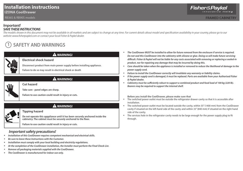
ELECTRICAL PREPARATION
A) Theswitched poweroutlet must beoutsidethe DishDrawer®
cavity so that it is accessibleafter installation.
B) Theswitched poweroutlet must bebetween 6" (150mm) and
18"(450mm) from the DishDrawer®cavity.
C) Referto Page9, Step5for electricalconnectionoptions.
Important!
The services holeinthe DishDrawer® cavityneedsto be large
enoughfor the plugonthe power supply cordto fit through, but MUST
NOTbe more than 11/z" (38ram).
PLUMBING 8DRAINAGE PREPARATION
,4) A readilyaccessiblevalvemust beinstalled in the water supply pipe.
B) If the supply pressureexceeds145 psi (1000kPa),thena pressure
limiting valve must be used.
C) Review PlumbingOptionson pages4 or 6. Choosea methodthat best
suitsyour needs.
B) A DrainHoseextensionKitP/N 525798will extendthe drain hoses
by 1413/4"(3.6m). Thekit isavailablefrom the nearestFisherSPaykel
AuthorizedServiceAgent. DONOTextend beyondthis limit.
E) This Dishwasher'smaximum drainheightis 371/2'' (950mm).
CAVITY PREPARATION
A) Theself-adhesivemoisture protectiontape must be appliedto the
undersideofthe countertopto preventmoisture damage,(referto
cavity diagrampg 3 or 5). Besure surfacesaredry and dust-free
priorto application.
B) Besure the cavity provides sufficient materialto securethe DishDrawer®
usingthe mountingtabs (referto step 1,page7). Ifthere is
nothingto screw to, addabrace. Seepage3 or 5 for screw locations.
C) Theservices hole MUSTbe immediatelyadjacentto the rearlower
cornerofthe cabinetry. Ifnot,the hoseswill preventthe
DishDrawer®beingpushedback intothe cavity allthe way. Thehole
canbe locatedon eitherside dependingon the location ofthe
services.
B) Besurethe cavity sidesareplumb (vertical)asthis will assist with
levellingthe DishDrawer®.
E) Minimumclearances:
POWER SUPPLY CORD
A) Careshouldbetaken when the applianceis installedor
removedto reducethe likelihoodof damageto the power
supply cord.
B) Ifthe power supply cordis damaged,it must be replacedby
the Manufacturer,ServiceAgent or asimilarly qualifiedperson
in orderto avoida hazard.
GROUNDING INSTRUCTIONS
A) This appliancemust be grounded. In the eventof malfunction or
breakdown,groundingwill reducethe riskof electric shockby
providingapath of leastresistancefor electric current.
/_WARNING!
Improper connectionofthe equipment-groundingconductorcanresult
in arisk of electricshock. Check with a qualified electrician or
service representativeif you are in doubt as to whether the appliance
is properlygrounded.
B) This applianceis equippedwith a power supply cord havingan
equipment-groundingconductor andan earthingplug. Thepower
supply plug must be pluggedintoan appropriateoutletthat is installed
andearthedin accordancewith all localCodesand Ordinances.
z_WARNING!
Donot modify the powersupplyplugprovidedwith the appliance - if
it wiJJnotfit the outlet, have aproperoutletinstalled by a qualified
electrician. Donot use an extension cord,adaptor plugor multiple
outlet box.
