Fisher-Rosemount Design CV500 User manual

D101640X012
Design CV500 Rotary Control Valve
Contents
Introduction 1. . . . . . . . . . . . . . . . . . . . . . . . . . . . . . .
Scope of Manual 1. . . . . . . . . . . . . . . . . . . . . . . . . . . . .
Description 2. . . . . . . . . . . . . . . . . . . . . . . . . . . . . . . . . .
Specifications 2. . . . . . . . . . . . . . . . . . . . . . . . . . . . . . .
Installation 2. . . . . . . . . . . . . . . . . . . . . . . . . . . . . . . . .
Maintenance 7. . . . . . . . . . . . . . . . . . . . . . . . . . . . . . .
Packing Maintenance 8. . . . . . . . . . . . . . . . . . . . . . . .
Stopping Leakage 8. . . . . . . . . . . . . . . . . . . . . . . . . .
Replacing Packing 8. . . . . . . . . . . . . . . . . . . . . . . . . .
Replacing Retainer, Seat Ring, and Face Seals 10.
Disassembly 11. . . . . . . . . . . . . . . . . . . . . . . . . . . . . .
Assembly 11. . . . . . . . . . . . . . . . . . . . . . . . . . . . . . . . .
Replacing Ball, Shaft, and Bearings 12. . . . . . . . . . .
Disassembly 12. . . . . . . . . . . . . . . . . . . . . . . . . . . . . .
Assembly 15. . . . . . . . . . . . . . . . . . . . . . . . . . . . . . . . .
Adjusting Actuator Travel 17. . . . . . . . . . . . . . . . . . . .
Changing Valve Flow Direction 18. . . . . . . . . . . . . . .
Changing Actuator Mounting Style 18. . . . . . . . . . . .
Parts Ordering 18. . . . . . . . . . . . . . . . . . . . . . . . . . . .
Parts Kits 18. . . . . . . . . . . . . . . . . . . . . . . . . . . . . . . . .
Parts List 19. . . . . . . . . . . . . . . . . . . . . . . . . . . . . . . . . .
Introduction
Scope of Manual
This instruction manual provides installation,
operation, maintenance, and parts ordering
information for 3- through 12-inch Design CV500 Cam
Vee-Ballrrotary control valves. Refer to separate
manuals for information concerning the actuator and
accessories.
Figure 1. Design CV500 Flanged Valve with Type 1052
Actuator and Type DVC6020 Positioner
Figure 2. Design CV500 Wafer Valve with
Type 1066 Actuator
W8192 / IL
W5000-1 / IL
Instruction Manual
Form 5302
April 2001 Design CV500
Design CV500
2
Table 1. Specifications
Valve Sizes
J3, J4, J6, J8, J10, and J12-inch
End Connection Style
JRaised-face flanges or Jring-type joint flanges
(ASME/ANSI B16.5). Valve bodies with DIN PN10
through PN100 flanges also available. Various
flangeless (wafer) body sizes are available in
certain ANSI and DIN ratings. Consult your Fisher
Controls sales office.
Maximum Inlet Pressure(1)
Consistent with applicable ANSI or DIN flange
ratings
Maximum Pressure Drops(1)
See tables 2 and 3
Shutoff Classification
Class IV per ANSI/FCI 70-2 and IEC 60534-4,
(0.01% of valve capacity at full travel), for either flow
direction.
Flow Characteristic
Approximately equal percentage
Flow Direction
JForward (normal) flow is into the convex side of
the V-notch ball
JBidirectional flow is into either side of V-notch
ball
Actuator Mounting
JRight-hand or Jleft-hand as viewed from the
upstream side of the valve
Mounting position depends on the desired open
valve position and flow direction required by
operating conditions.
Valve Ball Rotation
Counterclockwise to close (when viewed from
actuator side of valve body) through 90 degrees of
ball rotation
Valve Body/Actuator Action
With diaphragm or piston rotary actuator,
field-reversible between Jpush-down-to-close
(extending actuator rod closes valve body) and
Jpush-down-to-open (extending actuator rod
opens valve body)
Shaft Diameters(2) and Approximate Weights
See table 4
1. The pressure/temperature limits in this manual and any applicable standard limitations should not be exceeded.
2. Shaft diameter and spline end must match available shaft diameter of actuator.
Description
The Design CV500 Cam-Vee-Ball rotary control valve,
has a Vee-BallRstyle segmented ball in a valve body
similar to the Design V500 valve. The Design CV500 is
a flanged (figure 1) or wafer (figure 2) valve with a
patented, self-centering seat, eccentrically rotating
V-notch ball, and splined valve shaft. Suitable for
forward or reverse flow use, this valve mates with a
variety of actuators to provide throttling or on-off
service. Both flanged and wafer valves mate with ANSI
flanges or DIN flanges.
Only personnel qualified through training or experience
should install, operate, and maintain this valve and
related equipment. If you have any questions
concerning these instructions, contact your Fisher
sales office before proceeding.
Specifications
Specifications for the Design CV500 rotary control
valve are listed in table 1.
Installation
WARNING
Personal injury or equipment damage
caused by sudden release of pressure
can result if the valve assembly is
installed where service conditions could
exceed the pressure drop limits given in
tables 2 and 3 or the valve rating. To
avoid such injury or property damage,
provide a relief valve for overpressure
protection as required by government or
accepted industry codes and good
engineering practices.

Design CV500
3
Table 2. Maximum Allowable Shutoff Pressure Drops(3), Psi
VALVE BODY
BEARING
TEMPERATURE
VALVE SIZE
VALVE BODY
MATERIAL
BEARING
MATERIAL
TEMPERATURE 3 4 6 8 10 12
MATERIAL
MATERIAL
_CBar
S44004
–29 to 149 41.4 41.4 41.4 24.1 24.1 27.6
WCC steel S44004
(440C SST)
149 to 204 41.4 41.4 41.4 23.8 24.1 27.6
WCC
steel
(440C
SST)
204 to 316 41.4 41.4 41.4 23.1 24.1 27.6
R30006
–46(1) to 204 41.4 41.4 20.7 15.1 24.1 27.6
R30006
(Alloy 6)
204 to 260 41.4 41.4 20.7 15.1 24.1 27.6
(All
oy
6)
260 to 316 41.4 41.4 20.7 15.1 24.1 27.6
WCC steel, DIN
1 0619 t l CF8M
–46(1) to 93 41.4 41.4 41.4 24.1 31 34.5
,
1.0619 steel, CF8M
(316 SST) DIN
93 to 149
41 4
41 4
41 4
24.1(5)
31
34 5
(316 SST), DIN
1.4581 SST
,
or PTFE/composition- 93 to 149 41.4 41.4 41.4 23.1(6) 31 34.5
1
.
4581
SST
,
or
CF3M(4) (316L SST)
PTFE/com osition
-
lined S31603(2)(4)
149 to 204
41 4
41 4
41 4
23.8(5)
31
34 5
CF3M
(316L
SST)
lined
S31603
(S316L SST) 149 to 204 41.4 41.4 41.4 22.1(6) 31 34.5
204 to 260(2)
41 4
41 4
41 4
23.4(5)
31
34 5
204 to 260
(2)
41.4 41.4 41.4 21.7(6) 31 34.5
_FPsi
S44004
–20 to 300 600 600 600 350 350 400
WCC steel S44004
(440C SST)
300 to 400 600 600 600 345 350 400
WCC
steel
(440C
SST)
400 to 600 600 600 600 335 350 400
R30006
–50(1) to 400 600 600 300 220 350 400
R30006
(Alloy 6)
400 to 500 600 600 300 220 350 400
(All
oy
6)
500 to 600 600 600 300 220 350 400
WCC steel, DIN
1 0619 t l CF8M
–50(1) to 200 600 600 600 350 450 500
,
1.0619 steel, CF8M
(316 SST) DIN
200 to 300
600
600
600
350(5)
450
500
(316 SST), DIN
1.4581 SST
,
or PTFE/composition- 200 to 300 600 600 600 335(6) 450 500
1
.
4581
SST
,
or
CF3M(4) (316L SST)
PTFE/com osition
-
lined S31603(2)(4)
300 to 400
600
600
600
345(5)
450
500
CF3M
(316L
SST)
lined
S31603
(S316L SST) 300 to 400 600 600 600 320(6) 450 500
400 to 500(2)
600
600
600
340(5)
450
500
400 to 500
(2)
600 600 600 315(6) 450 500
1. –29_C (–20_F) for WCC steel valve body material.
2. For hot water or steam service, limit maximum temperature to 260_C (500_F).
3. The pressure or temperature limits in this table or in any applicable code limitation, should not be exceeded.
4. Standard material offerings from Fisher in Europe only.
5. S17400 (17-4PH SST) shaft only.
6. ASME SA-479 Grade SM-19 stainless steel shaft only. Pressure drops appropriate for both shaft materials.
CAUTION
When ordered, the valve configuration
and construction materials were
selected to meet particular pressure,
pressure drop, temperature, and
controlled fluid conditions. Since some
body/trim material combinations are
limited in their pressure drop and
temperature range capabilities, do not
apply any other conditions to the valve
without first contacting your Fisher
Controls sales office.
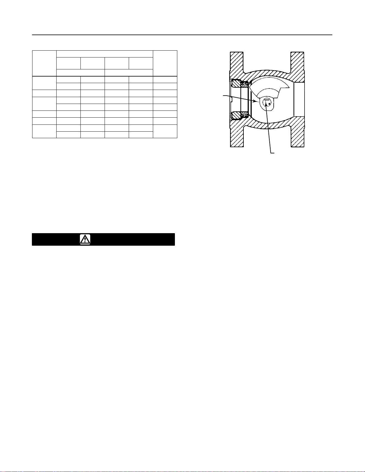
Key numbers are shown in figure 11 for 3 through
8-inch sizes and in figure 12 for 10 and 12-inch sizes.
1. If the valve body (key 1) is to be stored before
installation, protect the flange mating surfaces and
keep the body cavity dry and clear of foreign material.
2. Install a three-valve bypass around the control
valve assembly if continuous operation will be
necessary during inspection and maintenance of the
valve.
3. A Design CV500 valve is normally shipped as part
of a control valve assembly, with a power or manual
actuator mounted on the valve. If the valve and
actuator have been purchased separately or if the
actuator has been removed from the valve, mount the
actuator according to the actuator instruction manual.
Also, adjust the actuator travel using the Adjusting
Actuator Travel procedure before installing the valve;
the required measurements cannot be made with the
valve installed.
4. Before starting the actual installation of the valve,
determine the proper installation orientation of the
V-notch ball (key 2) and actuator. Determine the flow
direction of the process fluid through the valve. See
figure 3.

Design CV500
4
Table 4. Shaft Diameters and Approximate Weights
SHAFT DIAMETERS
APPROXIMATE WEIGHTS
SHAFT DIAMETERS Flanged Wafer
VALVE SIZE Through
Body At Spline
End(1) Class 150 Class 300 Class 600 Class 150 Class 300 Class 600
mm kg kg
3
25.4 25.4
19
24
26
16
16
16
325.4 19.1 19 24 26 16 16 16
431.8 31.8 36 42 50 34 34 34
6
38.1 38.1
54
69
93
50
50
638.1 31.8 54 69 93 50 50 –––
838.1 38.1 79 98 135 57 68 –––
10 44.5 44.5 ––– 208 ––– ––– ––– –––
12
53.8 53.8
253
12 53.8 50.8 ––– 253 ––– ––– ––– –––
Inches Pounds Pounds
3
1.00 1.00
42
52
57
35
35
35
31.00 0.75 42 52 57 35 35 35
41.25 1.25 79 93 111 75 75 75
6
1.50 1.50
120
152
204
110
110
61.50 1.25 120 152 204 110 110 –––
81.50 1.50 75 217 298 125 150 –––
10 1.75 1.75 ––– 458 ––– ––– ––– –––
12
2.12 2.12
558
12 2.12 2.00 ––– 558 ––– ––– ––– –––
1. Spline diameter that connects to actuator versus shaft diameter.
Note
For control valves used in slurry service,
mount the actuator and install the
control valve so that the V-notch ball
rotates above the valve drive shaft (refer
to figure 3), if possible.
5. Before installing the valve, make sure the flow
direction arrow (key 32) on the valve (key 1) matches
the actual process fluid flow direction through the valve
for the application where the valve will be installed.
Note
For best shutoff performance, install the
valve with the drive shaft horizontal and
the Vee-Ball closing in the downward
direction for standard right hand
mounting.
6. Install the flange gaskets and insert the valve
between the mating pipeline flanges. For wafer valves,
also make sure the mating line flanges are aligned.
Use flat sheet gaskets compatible with the process
media, or spiral wound gaskets with
compression-controlling center rings.
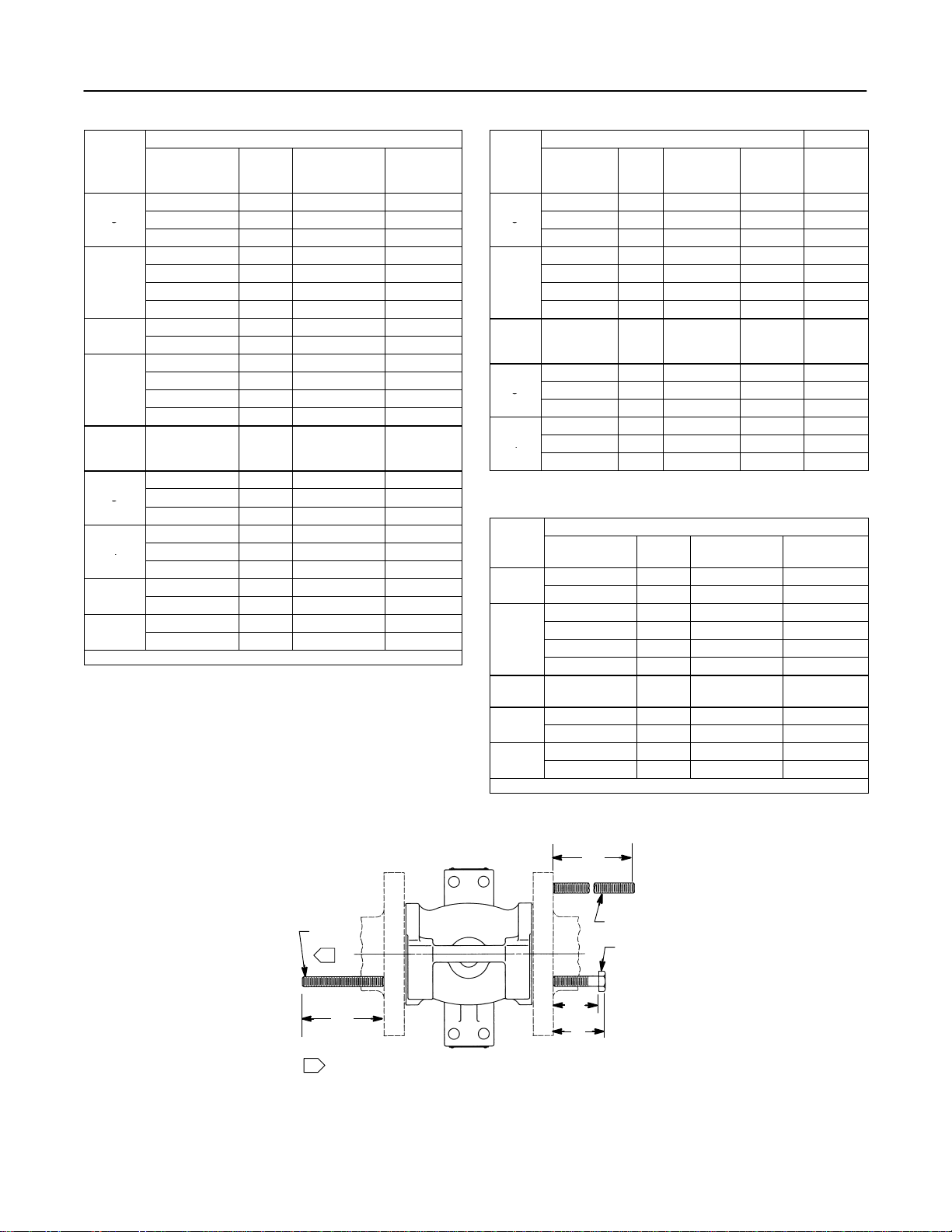
7. For wafer valves, consult the line bolt clearances
required (listed in figure 4) before installing the line
bolts and nuts.
For all valves, install the line bolts and nuts; then,
tighten them using accepted bolting procedures.
These procedures include, but are not limited to,
lubricating the line bolts and hex nuts and tightening
the nuts in a crisscross sequence to ensure proper
gasket load.
8. If a purge is desired for the purged bearing
construction, remove the pipe plugs (keys 29 and 24)
and install the purge lines. Purge pressure should be
greater than the pressure within the valve and the
purge fluid should be as clean as possible.
WARNING
A Design CV500 drive shaft is not
necessarily grounded when installed in a
pipeline unless the shaft is electrically
bonded to the valve.
To avoid personal injury or property
damage resulting from the effects of a
static electricity discharge from valve
components in a hazardous atmosphere
or where the process fluid is
combustible, electrically bond the drive
shaft (key 3) to the valve according to
the following step.

Design CV500
5
Figure 3. Index Marks for Actuator Lever Orientation.
ACTUATOR POSITION
ACTUATOR
MOUNTING STYLE VALVE OPEN 1234
NOTES:
1. ARROW ON LEVER INDICATES DIRECTION OF ACTUATOR THRUST TO CLOSE VALVE.
2. PDTC—PUSH DOWN TO CLOSE; PDTO—PUSH DOWN TO OPEN.
3. F—FORWARD FLOW; R—REVERSE FLOW.
RIGHT
-
HAND
STYLE A
(PDTC)
STYLE B
(PDTO)
STYLE C
(PDTO)
STYLE D
(PDTC)
LEFT-
HAND
F
R
F
R
F
R
F
R
C0741 / IL
Design CV500
6
Line Studs (Key 36) M(1)
Valve
Size DIN Qty Bolt Size Bolt
Length,
mm
PN 10-40 6M16 x 2 260
3PN63 6M20 x 2.5 300
3
PN100 6M24 x 3 325
PN10 & 16 6M16 x 2 285
4
PN25 & 40 6M20 x 2.5 300
4PN63 6M24 x 3 325
PN100 6M27 x 3 355
6
PN10 & 16 5M20 x 2.5 350
6PN25 & 40 5M24 x 3 375
PN10 10 M20 x 2.5 350
8
PN16 10 M20 x 2.5 350
8PN25 10 M24 x 3 375
PN40 10 M27 x 3 390
Valve
Size ANSI Class Qty Bolt Size Bolt
Length,
Inches
150 45/8-11 UNC 10.62
3300 63/4-10 UNC 11.12
3
600 63/4-10 UNC 11.50
150 65/8-11 UNC 11.44
4300 63/4-10 UNC 12.12
4
600 67/8-9 UNC 13.62
6
150 53/4-10 UNC 13.62
6300 93/4-10 UNC 14.38
8
150 83/4-10 UNC 13.62
8300 10 7/8-9 UNC 15.38
1. These bolts may be installed from either end of the valve body.
Cap Screws (Key 37) N P
Valve
Size DIN Qty Bolt Size Bolt
Length,
mm
Overall
Length,
mm
PN 10-40 4M16 x 2 50 60
3PN63 4M20 x 2.5 60 73
3
PN100 4M24 x 3 70 85
PN10 & 16 4M16 x 2 50 60
4
PN25 & 40 4M20 x 2.5 60 73
4PN63 4M24 x 3 70 85
PN100 4M27 x 3 80 97
Valve
Size ANSI Class Qty Bolt Size Bolt
Length,
Inches
Overall
Length,
Inches
150 ––– ––– ––– –––
3300 43/4-10 UNC 2.38 2.88
3
600 43/4-10 UNC 2.38 2.88
150 45/8-11 UNC 2.00 2.44
4300 43/4-10 UNC 2.38 2.88
4
600 47/8-9 UNC 2.75 3.38
Line Studs (Key 36)(1)
Valve
R
Valve
Size DIN Qty Bolt Size Bolt Length,
mm
6
PN10 & 16 6M20 x 2.5 110
6PN25 & 40 6M24 x 3 125
PN10 4M20 x 2.5 110
8
PN16 4M20 x 2.5 110
8PN25 4M24 x 3 125
PN40 4M27 x 3 135
Valve
Size ANSI Class Qty Bolt Size Bolt Length,
Inches
6
150 63/4-10 UNC 5.00
6300 63/4-10 UNC 5.00
8
150 ––– ––– –––
8300 47/8-9 UNC 5.62
1. Use instead of cap screws.
Figure 4. Line Bolt Dimensions for Wafer Valves (3 through 8-Inch Sizes Only).
RN
P
M
LINE
STUDS
LINE STUDS
CAP
SCREWS
1
NOTE:
USED INSTEAD OF CAP SCREWS
1
A4347/IL
Design CV500
7
Note
Standard Design CV500 packings
(key 13) are composed either entirely of
conductive packing rings (graphite
ribbon packing) or partially of
conductive packing rings (a carbon-filled
PTFE female adaptor with PTFE V-ring
packing or a graphited-composition
packing ring with PTFE/composition
packing) in order to electrically bond the
shaft to the body for hazardous area
service. Alternate shaft-to-body bonding
can be provided with the following step.
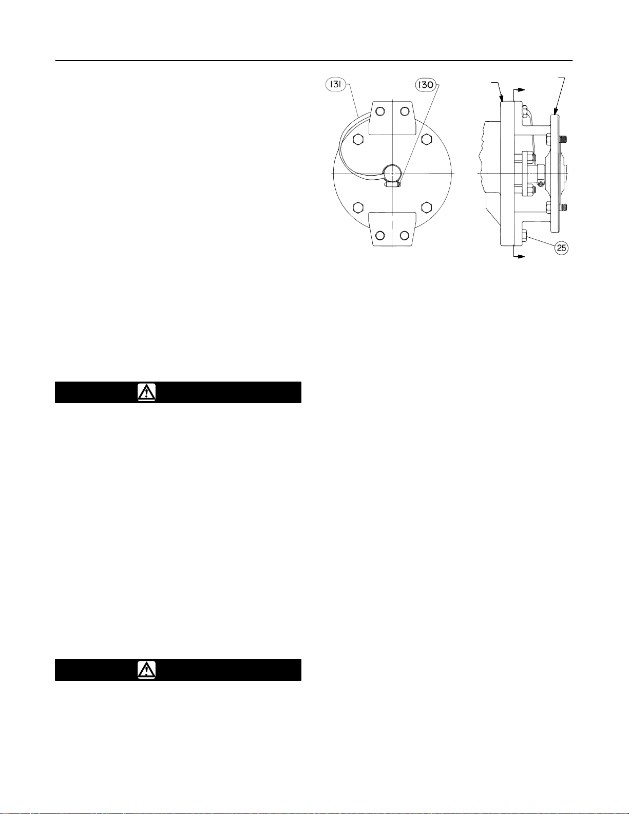
9. For hazardous applications, attach the bonding
strap assembly (key 131, figure 5) to the shaft with the
clamp (key 130, figure 5) and connect the other end of
bonding strap assembly to the body with the cap screw
(key 25, figure 5).
10. Connect pressure lines to the actuator as
indicated in the actuator instruction manual. When a
manual actuator (handwheel) is used with a power
actuator, install a bypass valve on the power actuator
(if not already supplied) for use during manual
operation.
WARNING
Personal injury could result from
packing leakage. Valve packing was
tightened before shipment; however, the
packing might require some
readjustment to meet specific service
conditions.
If the valve has ENVIRO-SEALrlive-loaded packing
installed, readjustment will probably not be required.
See the instruction manual titled ENVIRO-SEAL
Packing System for Rotary Valves for packing
instructions. If you wish to convert your present
packing arrangement to ENVIRO-SEAL packing, refer
to the retrofit kits listed in the parts kit sub-section near
the end of this manual.
Maintenance
WARNING
Avoid personal injury or property
damage from sudden release of process
pressure or bursting of parts. Before
performing any maintenance operations:
Figure 5. Optional Shaft-to-Body Bonding Strap Assembly
VALVE BODY ACTUATOR
A
AVIEW A-A
37A6528-A
A3143-2/IL
DDisconnect any operating lines
providing air pressure, electric power, or
a control signal to the actuator. Be sure
the actuator cannot suddenly open or
close the valve.
DUse bypass valves or completely
shut off the process to isolate the valve
from process pressure. Relieve process
pressure on both sides of the valve.
Drain the process media from both sides
of the valve.
DVent the power actuator loading
pressure and relieve any actuator spring
precompression.
DUse lock-out procedures to be sure
that the above measures stay in effect
while you work on the equipment.
DAlways wear protective gloves,
clothing, and eyewear when performing
any maintenance operations to avoid
personal injury.
DThe valve packing area may contain
process fluids that are pressurized, even
when the valve has been removed from
the pipeline. Process fluids may spray
out under pressure when removing the
packing hardware or packing rings.
Valve parts are subject to normal wear and must be
inspected and replaced as necessary. The frequency
of inspection and replacement depends upon the
severity of service conditions.
Due to the care Fisher takes in meeting all
manufacturing requirements (heat treating,
dimensional tolerances, etc.), use only replacement
parts manufactured or furnished by Fisher.

Design CV500
8
Packing Maintenance
Key numbers refer to figure 11 for 3 through 8-inch
sizes and to figure 12 for 10 and 12-inch sizes unless
otherwise indicated.
Note
For the ENVIRO-SEAL packing system,
refer to the Parts List section for retrofit
kits, parts kits, and individual parts (see
figures 13 and 14). Refer to separate
ENVIRO-SEAL instruction manual for
maintenance instructions.
Standard ENVIRO-SEAL packing
systems can be used in vacuum service
with packing rings in the standard
orientation. It is not necessary to reverse
the ENVIRO-SEAL PTFE packing rings.
Stopping Leakage
All maintenance procedures in this section may be
performed with the valve body (key 1) in the line.
For packings other than spring-loaded packing,
leakage around the packing follower (key 14) can be
stopped by tightening the packing flange nuts (key 16).
If leakage cannot be stopped in this manner, replace
the packing according to the Replacing Packing
procedure.
If the packing is relatively new and tight on the drive
shaft (key 3), and if tightening the packing nuts does
not stop leakage, it is possible that the shaft is worn or
nicked so that a seal cannot be made. If the leakage
comes from the outside diameter of the packing, it is
possible that the leakage is caused by nicks or
scratches on the packing box wall. Inspect the shaft
and packing box wall for nicks or scratches when
performing the following procedures.
Replacing Packing
Note
If the valve has ENVIRO-SEAL
live-loaded packing installed, see the
manual entitled ENVIRO-SEAL Packing
System for V-Line and edisc Rotary
Valves.
This procedure may be performed without removing
the actuator from the valve if adding
PTFE/composition packing rings as a temporary
measure. However, the actuator must be removed if
replacing any other kind of packing or if the metal
packing parts (keys 14, 17, and, if used, 18) need to
be replaced.
1. Isolate the control valve from the line pressure,
release pressure from both sides of the valve body,
and drain the process media from both sides of the
valve. If using a power actuator, also shut-off all
pressure lines to the power actuator, release all
pressure from the actuator. Use lock-out procedures to
be sure that the above measures stay in effect while
you work on the equipment.
CAUTION
To avoid increased leakage, increased
valve component wear or possible
damage to the valve body, ball, shaft,
and bearings resulting from a sharp
blow to the shaft, use a wheel puller to
separate the actuator parts from the
drive shaft.
Do not drive the actuator parts off the
drive shaft since this could move the
valve bearings, shaft, and ball away from
proper alignment, causing improper
seating of the ball. Such misalignment
may result in damage to valve
components if the valve is returned to
service without disassembly and
inspection of the valve ball alignment.
2. If necessary, remove the cap screws (key 25) and
hex nuts (key 26). Then remove the actuator while
referring to the actuator instruction manual for
assistance.
3. Remove the packing nuts (key 16). For 3 through
8-inch sizes, remove the packing follower (key 14). For
10 and 12-inch sizes, remove the packing flange (key
45) and then remove the packing follower (key 14).
4. Remove the old packing rings (key 13), packing
box ring (key 17), and, if used, the lantern ring (key
18). Do not scratch the valve shaft or packing box wall;
scratching these surfaces could cause leakage. Clean
all accessible metal parts and surfaces to remove
particles that would prevent the packing from sealing.
5. Whenever you are installing new packing, be sure
the ball (key 2) is closed while you install and tighten
the new packing. Install the new packing rings and
packing box ring by stacking the parts as shown in
figure 6. Make sure split rings are arranged so that the
splits do not line up to form a leak path. Then slide the
stack into the packing box as far as they will go while
being careful to avoid trapping air among the rings.
6. Install the packing follower (key 14), and, for 10 and
12-inch sizes, also install the packing flange (key 45).
Install the nuts (key 16), and tighten them far enough
to stop leakage under normal conditions.
7. Mount the actuator while referring to the actuator
mounting procedures in the actuator instruction

Design CV500
9
Figure 6. Packing Arrangements
C0587-4 / IL
BRAIDED PTFE COMPOSITION & GRAPHITE RIBBON
DOUBLE PACKING ARRANGEMENTS
PTFE/VĆRING DOUBLE PACKING ARRANGEMENTS
SINGLE PACKING ARRANGEMENTS
LEAKOFF ARRANGEMENT DOUBLE PACKING
ARRANGEMENT
PRESSURE SERVICE VACUUM SERVICE PRESSUREĆVACUUM SERVICE
FOR PURGED BEARING
CONSTRUCTION
FOR PURGED BEARING
CONSTRUCTION
GRAPHITE RIBBON OR
PTFEĆCOMPOSITION PACKING
PTFE VĆRING
NOTES:
INCLUDES ZINC WASHERS (KEY 28) FOR GRAPHITE
RIBBON PACKING ONLY
INCLUDED IN PTFE/V-RING PACKING SET (KEY 13).
FOR ONLY PTFE/BOUND-COMPOSITION PACKING,
TOP RING IS CONDUCTIVE GRAPHITE FILAMENT RING.
1
2
3

Design CV500
10
Figure 6. Packing Arrangements (Continued)
PTFE/COMPOSITION OR GRAPHITE ENVIROĆSEAL PACKING ARRANGEMENTS
C0774-1 / IL
manual. Complete the Adjusting Actuator Travel
procedure in this manual before installing the valve in
the pipeline. This is necessary due to the
measurements that must be made during the actuator
adjustment process.
8. When the control valve is being put back into
operation, check the packing follower for leakage, and
retighten the packing nuts as necessary.
Replacing Retainer, Seat Ring, and
Face Seals
This procedure is to be performed if the control valve
is not shutting off properly, if installing a different seat
ring, or if seat ring inspection is necessary. The
actuator and valve must be removed from the pipeline;
however, the actuator may remain mounted during this
procedure. Key numbers refer to figure 11 for 3
through 8-inch sizes and to figure 12 for 10 and
12-inch sizes unless otherwise indicated.
A retainer tool is required to remove the retainer
(key 5). If specifically ordered, a tool is supplied with
the valve; a tool can also be ordered individually by
referencing the tool part number as shown in key 33 of
the Parts List. If desired, a tool can be machined using
the dimensions shown in figure 7.
During assembly, handle the retainer, seat ring, and
face seals carefully. Critical areas that must be
protected are the threads and inner surface of the
retainer (key 5), the sealing surfaces of the face seals
(key 8), the face seal grooves in the seat ring (key 4),

Design CV500
11
the shutoff surface of the seat ring, and the face seal
surface in the valve body.
A new retainer gasket (key 11) is required whenever
the retainer (key 5) is removed. Other parts that are in
good condition can be reused.
Disassembly
1. Isolate the control valve from the line pressure,
release pressure from both sides of the valve body,
and drain the process media from both sides of the
valve. If using a power actuator, also shut-off all
pressure lines to the power actuator, release all
pressure from the actuator. Use lock-out procedures to
be sure that the above measures stay in effect while
you work on the equipment.
2. Remove line bolting. Then, remove the control
valve from the pipeline and place the valve on a flat
surface with the retainer (key 5) facing up.
3. Rotate the drive shaft (key 3) to move the ball (key
2) into the open position.
Note
The retainer (key 5) was installed at
the factory using the torque listed in
figure 7.
4. Remove the retainer (key 5) by engaging the
retainer tool, attaching an impact wrench or other
suitable tool, and unscrewing the retainer. Inspect the
retainer. Place it on a protected, flat surface where the
threads and inner surface will not be contaminated or
damaged.
5. Remove the retainer gasket (key 11). Inspect the
gasket surface in the valve body.
6. Lift out the seat ring (key 4) and both face seals
(key 8). Inspect the parts and place them on a flat,
protected surface.
7. Inspect the shutoff surface of the V-notch ball. If it
is worn, nicked, or scratched, proceed to the
Replacing Ball, Shaft, and Bearings procedure. If the
parts are in good condition and do not require
replacement, continue to the Assembly procedure.
Assembly
WARNING
Seat ring installation requires that the
ball (key 2) remain in the open position.
To avoid personal injury or damage to
tools, valve parts, or other items
resulting from ball closing, prevent
against ball travel by using travel stops,
manual actuators, constant supply
pressure to a pneumatic actuator, or
other steps as appropriate. When
installing the seat ring, keep hands,
tools, and other objects out of the valve.
1. Apply enough supply pressure to the actuator to
open the ball, or take other steps to hold the ball open.
2. Clean the valve body, the retainer threads, the
retainer gasket surface, and the seat ring sealing
surface.
3. Using either face seals (key 8) in good condition or
new face seals, place one seal in the seat ring cavity
of the valve body.
Note
The seat ring (key 4) may have one or
two shutoff surfaces. The shutoff
surfaces are the narrow, rounded edges
of the seat ring bore. Inspect the seat
ring and locate the shutoff surfaces
before proceeding.
Make sure the ball (key 2) is open while you install the
seat ring (key 4) and retainer ring (key 5). Before
installing the seat ring, open the ball or plug.
Insert a screw driver, pry bar, or similar tool between
the lower ear of the ball and the valve body. Use the
pry to move the ball tightly against the thrust washer
and bearing stop (key 7) on the actuator side of the
valve. Keep the ball in that position until you finish
installing the seat ring.
4. Insert the seat ring into the seat ring cavity with the
correct shutoff surface facing the V-notch ball and
shaft. The seat ring will cover the face seal installed in
step 3.
5. Place the second face seal (key 8) on the seat ring
(key 4).
6. Apply Never-Seez Pure Nickel Special lubricant or
equivalent to the gasket surface in the valve body.
Install the gasket (key 11), while making certain that
the concave surface of the gasket is up (hump surface
of gasket down).
7. Apply Never-Seez Pure Nickel Special lubricant, or
equivalent, to the threads and bottom of the retainer
(key 5) only in the area that contacts the gasket.
Thread the retainer into the valve body.
8. Refer to figure 7. Find the correct retainer torque for
the valve size. With the appropriate tool, tighten the
retainer to the torque listed in figure 7.
9. A gap between the seat ring (key 4) and retainer
(key 5) allows the seat ring to self-center. Applying the
proper amount of torque during installation should
position the retainer and seat ring properly. Use a

Design CV500
12
feeler gage to measure between the parts as shown in
figures 11 and 12, making certain the necessary
clearance exists. Compare the measured gap to the
clearance in table 5; proceed as follows:
Table 5. Assembly Clearance
PROCESS
SEAT RING AND RETAINER CLEARANCE
PROCESS
TEMPERATURE
mm Inches
TEMPERATURE
Minimum Maximum Minimum Maximum
To 260_C
(500_F)(1) 0.08 0.30 0.003 0.012
Over 260_C
(500_F)(2) 0.20 0.30 0.008 0.012
1. Standard Trim
2. Special High Temperature Trim
DIf the measured clearance is within table values,
proceed to the next step.
DIf the measured gap is larger than the maximum,
tighten the retainer—apply more torque than that listed
in figure 7, if necessary, until the clearance is within
maximum and minimum values.
DIf the measured clearance is smaller than the
minimum, remove the retainer, seat ring, and face
seals, clean the parts, and reassemble so as to obtain
the necessary minimum clearance.
10. Perform the Adjusting Actuator Travel procedure
and then install the control valve in the pipeline.
Replacing Ball, Shaft, and Bearings
Perform this procedure to replace the ball (key 2),
expansion pin (key 9), taper pin (key 10), drive shaft
(key 3), follower shaft (key 38), groove pins (key 39),
or bearings (keys 6 and 42). These parts are
independently replaceable; for example, installing a
new ball does not require replacing a reusable valve
shaft or expansion pin assembly. Key numbers refer to
figure 11 for 3 through 8-inch sizes and to figure 12 for
10 and 12-inch sizes unless otherwise indicated.
Disassembly
WARNING
To avoid personal injury resulting from
contact with edges of the V-notch ball
(key 2) and seat ring (key 4) during ball
rotation, stay clear of its edges when
rotating the ball. To avoid damage to
tools, valve parts, or other items
resulting from V-notch ball rotation,
keep tools and other property away from
the edges of the ball.
When the actuator is removed from the
valve, the ball/shaft assembly may
suddenly rotate, resulting in personal
injury or property damage. To avoid
injury or damage, carefully rotate the
ball/shaft assembly to a stable position
in the valve body after the actuator is
disconnected.
CAUTION
To avoid increased leakage, increased
valve component wear or possible
damage to the valve body (key 1), ball
(key 2), drive shaft (key 3), follower shaft
(key 38), and bearings (keys 6 and 42)
resulting from a sharp blow to the
actuator or valve parts, use a wheel
puller to separate the actuator parts
from the valve drive shaft.
Do not drive the actuator parts off the
valve drive shaft since this could move
the valve bearings, shafts, and ball away
from proper alignment, causing
improper seating of the ball. Such
misalignment may result in damage to
valve components if the valve is
returned to service without disassembly
and inspection of the ball alignment.
1. Isolate the control valve from the line pressure,
release pressure from both sides of the valve body,
and drain the process media from both sides of the
valve. If using a power actuator, also shut-off all
pressure lines to the power actuator, release all
pressure from the actuator. Use lock-out procedures to
be sure that the above measures stay in effect while
you work on the equipment.
2. Remove the actuator cover. Note the actuator
orientation with respect to the valve body and the lever
orientation with respect to the valve drive shaft (see
figure 3). Remove the lever but do not loosen the
actuator turnbuckle adjustment. Remove the actuator
mounting screws and nuts, and remove the actuator. If
necessary, refer to the actuator instruction manual for
assistance.
3. With the valve body (key 1) out of the pipeline,
loosen the packing nuts (key 16). If the packing is to
be reused, do not remove it. However, Fisher
recommends that the packing be replaced whenever
the drive shaft is removed.
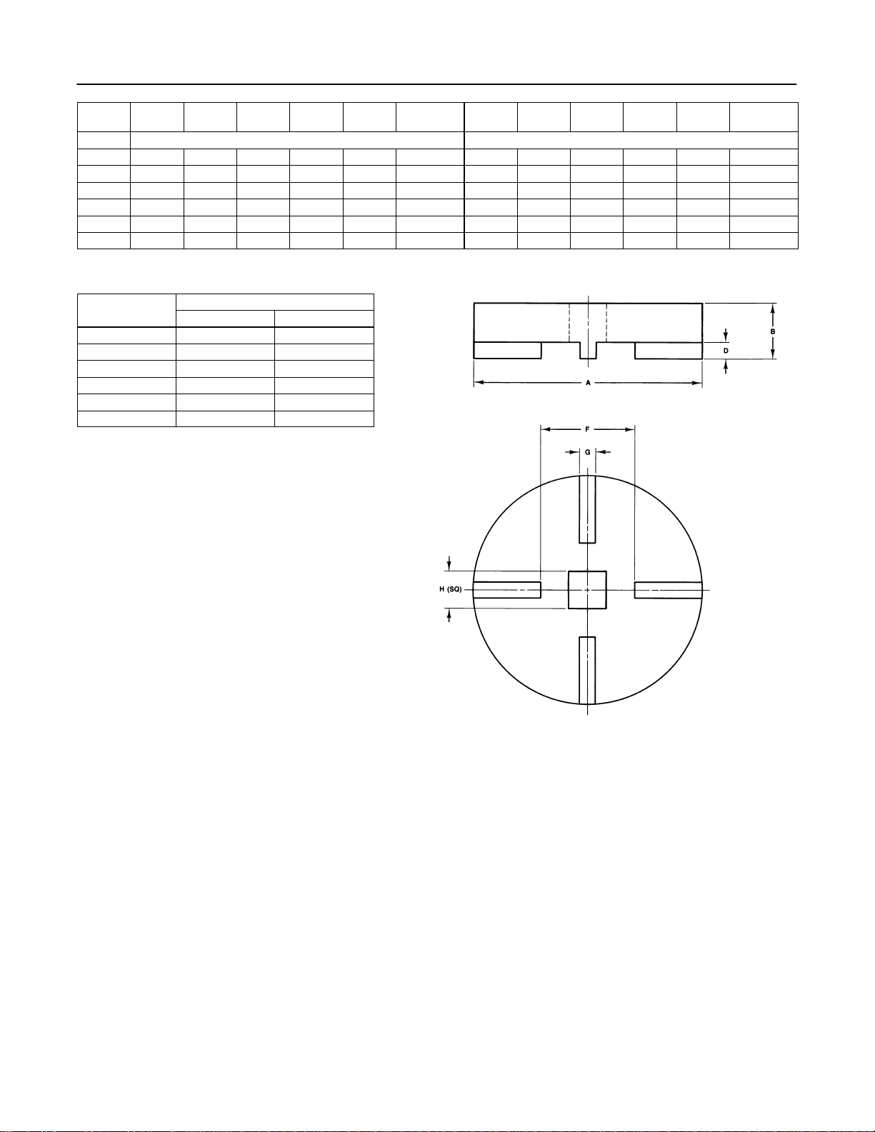
RETAINER TOOL FOR 3 THROUGH 12ĆINCH
VALVE SIZES
B1899-1 / IL
Figure 7. Data for Making and Using Retainer Tool
Design CV500
13
VALVE
SIZE A B D F G H
(SQUARE) A B D F G H
(SQUARE)
mm Inches
379.2 33.3 7.9 41.4 7.9 19.0 3.12 1.31 .31 1.62 .31 .75
4104.6 33.3 7.9 41.4 7.9 25.4 4.12 1.31 .31 1.62 .31 1.00
6155.4 38.1 11.2 63.5 11.2 25.4 6.12 1.50 .44 2.50 .44 1.00
8203.2 50.8 11.2 101.6 11.2 38.1 8.00 2.00 .44 4.00 .44 1.50
10 241.3 50.8 11.2 127.0 19.1 38.1 9.5 2.00 .44 5.00 .75 1.50
12 273.0 50.8 11.2 127.0 25.4 38.1 10.75 2.00 .44 5.00 1.00 1.50
VALVE SIZE
RETAINER TORQUE
VALVE SIZE NSmLbfSft
3515 380
41170 860
62305 1700
83120 2300
10 4750 3500
12 6100 4500
4. Rotate the V-notch ball (key 2) to the fully open
position.
5. Drive out the groove pin (key 39) that secures the
ball (key 2) to the follower shaft (key 38). Remove the
groove pin from the ball ear in the direction shown in
figure 8.
Using a pin punch and hammer, firmly strike the
chamfered end of the expansion pin through the
smaller hole. You may need to bend the pin or drill the
pin before it can be completely removed. Remove both
pins from the ball ear in the direction shown in figure 8.
Driving the pins in the other direction will tighten the
pins.
6. For 3 through 8-inch sizes, remove the pipe plug
(key 29). Using a punch, drive the follower shaft (key
38) into the center of the ball (key 2). Use care to
avoid dropping the follower shaft.
7. For 10 and 12-inch sizes, remove the hex nuts
(key 44), and then remove the bottom flange (key 40).
Thread a bolt into the end of the follower shaft and pull
the follower shaft out of the valve. Refer to table 6 for
thread sizes. The bearing (key 6) may come out with
the follower shaft.
Design CV500
14
Table 6. Data for Tapped Holes on Valve Shaft
SHAFT DIAMETER
THREAD
VALVE
SIZE Through
Valve At Spline
End Through
Valve At Spline
End
THREAD
SIZE,
UNC
SIZE
mm Inches
UNC
3
25.4 25.4 1.00 1.00 3/8-16
325.4 19.1 1.00 0.75 5/16-18
431.8 31.8 1.25 1.25 3/8-16
6
38.1 38.1 1.50 1.50 1/2-13
638.1 31.8 1.50 1.25 3/8-16
838.1 38.1 1.50 1.50 1/2-13
10 44.5 44.5 1.75 1.75 1/2-13
12
53.8 53.8 2.12 2.12
3/4 10
12 53.8 50.8 2.12 2.00 3/4-10
8. For 3 through 8-inch sizes, Refer to figure 8. The
expansion pin (key 9) and the taper pin (key 10) inside
of it are holding the ball in position on the drive shaft.
Find the larger hole in the ball ear where these pins
enter the ear. On the opposite side of the ear is a
smaller hole where the chamfered end of the
expansion pin rests on the inner lip of the hole.
9. For 10 and 12-inch sizes, drive out the groove pin
that secures the ball to the drive shaft. Remove the
groove pin from the ball ear in the direction shown in
figure 8.
WARNING
To avoid personal injury or damage to
tools, valve parts, or other items
resulting from the ball (key 2) falling
from the valve body, support the ball to
prevent it from falling as the drive shaft
(key 3) is being removed.
10. Pull the drive shaft (key 3) from the valve body. If
the shaft cannot be removed by hand, attach a slide
hammer or similar tool to the spline end of the shaft
that was attached to the actuator. If the shaft has a
tapped hole at the spline end of the shaft; refer to
table 6 for thread sizes.
11. Remove the ball (key 2), and thrust washers
(key 12) from the valve body.
Note
For 3 through 8-inch sizes, two shaft
bearings (key 6) are located inside the
valve body on either side of the ball.
Only one of these two bearings is
identified by key 6. The other bearing is
located along the drive shaft on the
other side of the V-notch ball.
Figure 8. Taper and Expansion Pin Removal from
Ball and Drive Shaft
E0575 IL
DRIVE PINS OUT
FROM THIS END
(SMALLER HOLE)
SLASH MARK ON SPLINED
END OF SHAFT
For 10 and 12-inch sizes, there are two
shaft bearings. One is identified as key
6, and the other is identified as key 42.
12. If the shaft bearings are to be replaced, remove
packing (key 13).
13. If the bearing closest to the packing (key 6 on 3
through 8-inch sizes and key 42 on 10 and 12-inch
sizes) requires replacement and cannot be removed
by hand, press it out using a ram with dimensions as
given in figure 9. The ram has a smaller diameter than
the bearing stop (key 7) so the bearing stop need not
be removed when pressing out the bearing on the
drive shaft. Insert the ram through the packing box and
press the bearing into the valve body cavity. Take care
not to move the bearing stop when pressing out the
bearing.
14. For 3 through 8-inch sizes, if the second bearing
(key 6) requires replacement and cannot be removed
by hand, use one of the following methods:
DKnock or pry the bearing out, or
DUse the valve drive shaft as a piston to drive the
bearing from the valve body. To accomplish this, install
the pipe plug (key 29). Fill the bearing bore with a
heavy grease and then insert the end of the shaft back
through the valve body and into the grease-filled
bearing. Protect the splined end of the shaft with, for
example, a block of wood; then strike the protected
end. When the shaft is struck, it will act as a piston,
pushing the grease into the bearing bore. The grease
will then force the bearing out of the bore and farther
along the shaft. Soon, the bearing will be positioned
for easy removal.

Design CV500
15
VALVE
SIZE
A MAX.
MIN. L
SIZE
mm Inches mm Inches
327.8
27.4 1.094
1.078 165 6.50
434.1
33.7 1.344
1.328 165 6.50
642.1
41.7 1.656
1.641 197 7.75
842.1
41.7 1.656
1.641 229 9.00
10 48.4
48.0 1.905
1.890 229 9.00
12 57.8
57.4 2.275
2.260 260 10.25
Figure 9. Ram Dimension for Bearing Removal
A3308 / IL
15. For 10 and 12-inch sizes, if the bearing (key 6)
on the follower shaft requires replacement and cannot
be removed by hand, press it out using a ram with
dimensions as given in figure 9. Press the bearing into
the valve body cavity.
16. If used, remove the O-rings (keys 19 and 20) from
the bearings. Also, for 3 through 8-inch sizes, remove
the pipe plug (key 29).
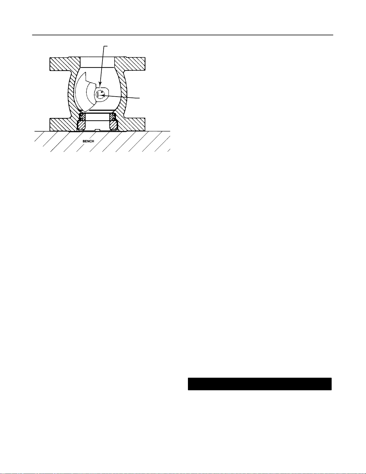
Assembly
Note
Before starting to assemble the valve
components, place the valve body (key
1) on a flat surface with the retainer (key
5) facing down as shown in figure 10.
This orientation of the valve allows
easier installation of the V-notch ball.
1. Thoroughly clean the parts before assembly.
2. If O-rings (keys 19 and 20) are used, apply a small
amount of lubricant to the O-rings so the bearings will
easily slide into the valve body. Insert the smaller
O-ring (key 20) inside the bearing and the larger
O-ring (key 19) around the outside of the bearing.
CAUTION
To avoid damage to O-rings resulting
from contact with sharp edges within the
bearing holes, use appropriate care
when installing the O-rings.
3. Slide the bearing for the follower shaft (key 6)
located opposite the packing box and, if used, O-rings
(keys 19 and 20) into the valve body. For 10 and
12-inch sizes, make certain the groove located on the
outside diameter of the bearing is positioned towards
the bottom flange side of the valve body.
4. Slide the bearing located on the packing box side
(key 6 for 3 through 8-inch sizes and key 42 for 10 and
12-inch sizes) into the valve body and against the
bearing stop.
5. For 3 through 8-inch sizes, inspect the drive shaft
(key 3). Insert the shaft end opposite the splined end
into the packing box and through the bearing that was
previously installed in the packing box in step 4. Stop
before the drive shaft enters the main valve body
cavity. Support the splined end of the shaft.
For 10 and 12-inch sizes, inspect the drive shaft (key
3). Insert the splined shaft end with the groove pin hole
into the packing box and through the bearing that was
previously installed in step 4. Stop before the drive
shaft enters the main valve body cavity. Support the
end of the drive shaft that extends out from the valve
body.
6. For 3 and 4-inch sizes, insert the follower shaft
through the outside of the ear of the V-notch ball that
has the smaller diameter (non-stepped) hole. Push the
follower shaft through the ear until the end of the
follower shaft with the groove pin hole is between the
ears and the other end of the follower shaft is flush
with outside edge of the ear. Place the ball in the valve
body cavity with the ear containing the follower shaft
adjacent to the follower shaft bore. Slide the follower
shaft through the ear of the ball and into the bearing
(key 6) which was previously installed in step 3.
For 6 and 8-inch sizes, locate the smaller diameter
hole in the V-notch ball ear. Place the ball in the valve
body cavity with the ear containing the smaller
diameter hole adjacent to the follower shaft bore.
Place the follower shaft between the ears of the
ball. Slide the follower shaft through the ear of ball
and into the bearing (key 6) that was previously
installed in step 3.
For 10 and 12-inch sizes, place the ball in the valve
body cavity. Slide the follower shaft, splined end first,
through the bearing (key 6), that was previously
installed in step 3, and into the ear of the ball. Align the
groove pin hole in the follower shaft with hole in the
ball ear.
Design CV500
16
Figure 10. Taper and Expansion Pin Insertion
into Ball and Drive Shaft
E0576 / IL
PINS GO IN FROM
THIS END (LARGER HOLE)
SLASH MARK
ON SPLINED
END OF SHAFT
7. For 3 through 8-inch sizes, position the ball so
that the larger hole is facing up, away from the seat
ring and retainer. Determine the correct orientation of
the V-notch ball (key 2) required by the specific
installation orientation of the valve and the flow
direction of the process fluid. See figure 3.
For 10 and 12-inch sizes, determine the correct
orientation of the V-notch ball (key 2) required by the
specific installation orientation of the valve and the
flow direction of the process fluid. See figure 3. The
groove pin hole in both the drive shaft (key 3) and the
ear of the ball are offset from center. Make certain the
holes will align.
Note
Before proceeding, inspect the V-notch
ball position once again to insure the
correct orientation. If the ball is not
properly installed, it will not rotate
properly and will not shutoff in service.
8. Hold the thrust washer (key 12) between the ball
(key 2) and the bearing installed next to the packing
(key 6 for 3 through 8-inch sizes and key 42 for 10 and
12-inch sizes.
For 10 and 12-inch sizes, align the zero mark located
on the end of the drive shaft with the zero mark
located on the ball ear.
For all sizes, slide the valve drive shaft (key 3) from
the packing box into the valve body through the thrust
washer and into the ear of the ball.
9. For 3 through 8-inch sizes, secure the ball in the
correct open position. Locate the slash mark on the
splined end of the valve drive shaft. Rotate the drive
shaft until the slash mark is vertical and facing out
from the center of the shaft in the same direction as
the ball seating surface. See figure 10.
Note
When the valve drive shaft is correctly
positioned for 3 through 8-inch sizes,
the slash mark on the splined end will be
parallel with the ball shutoff surface. See
figure 10. Step 9 is not required for 10
and 12-inch sizes because the drive
shaft and the ear of the ball are both
splined and were aligned in step 8.
10. Secure the ball to the follower shaft by aligning the
groove pin hole in the ball ear and the hole on the
opposite side of this ear with the groove pin hole
through the follower shaft (key 38).
11. Use pin punches to drive in the groove pin until it
is flush with the surface of the ball ear. Stake both
ends of the pin hole in the ball ear to retain the pin
during this step.
12. Secure the ball to the drive shaft (key 3) as
follows:
DFor 3 through 8-inch sizes:
a. The groove pin holes in both the drive shaft
(key 3) and the ear of the ball are offset from
center. Make certain the holes in the ear of the ball
will align with the hole in the drive shaft. Secure the
ball to the drive shaft by using pin punches and
driving in the groove pin until it is flush with the
surface of the ball ear. Make certain that the
groove pin goes completely.
Note
If the holes in the ball ear do not line up
with the hole in the drive shaft, check
the slash mark on the splined end of the
shaft. Make sure the shaft and ball are
properly oriented.
b. Place the chamfered end of the expansion pin
(key 9) into the larger hole in the ball ear (see
figure 10).
CAUTION
To avoid damage to the expansion pin,
ball, or drive shaft resulting from the
application of excessive force on the
expansion pin, use appropriate care
when driving the expansion pin through

Design CV500
17
the ball and drive shaft. Use the correct
tool. Do not use excessive force.
c. Drive the expansion pin into the larger hole until
the chamfered end of the pin reaches the inner lip
of the smaller hole on the opposite side of the ball.
Closely observe the progress of the pin to avoid
striking it after it has reached the lip of the smaller
hole.
d. Place the taper pin (key 10) into the open end of
the expansion pin. Drive the taper pin into the
expansion pin until the pins, ball, and drive shaft
are snug. Do not attempt to drive either pin flush
with the ear.
DFor 10 and 12-inch sizes, the groove pin holes
in both the drive shaft (key 3) and the ear of the ball
are offset from center and have spline ridges. Make
certain the holes in the ear of the ball will align with the
hole in the drive shaft. Secure the ball to the drive
shaft by using pin punches and driving in the groove
pin until it is flush with the surface of the ball ear.
Make certain that the groove pin goes completely
through the drive shaft and into the opposite side of
the ball ear.
13. Rotate the ball by hand to check that it rotates
properly. If rotation interferes with the valve body, drive
out the taper and expansion pins (keys 9 and 10) for 3
through 8-inch sizes and the groove pin (key 39) that
fastens the drive shaft to the ball for 10 and 12-inch
sizes. Remove the drive shaft (key 3), and repeat this
procedure starting with step 5.
14. For 3 through 8-inch sizes, install the pipe plug
(key 29).
15. For 10 and 12-inch sizes, install the bottom
flange (key 40), and then install and tighten the hex
nuts (key 44) and gasket. Make sure the pipe plug
(key 29) is installed in the bottom flange.
16. If the seat ring (key 4), face seals (key 8), and
retainer (key 5) need to be installed, complete the
Assembly portion of the Replacing Retainer, Seat
Ring, and Face Seals procedure. If the seat ring has
previously been installed, proceed to Adjusting
Actuator Travel. If the packing has been removed, be
sure to refer to the Packing Maintenance procedures
to replace the packing before installing the actuator on
the valve.
Adjusting Actuator Travel
Perform this procedure whenever the actuator is
removed or disconnected from the valve and
whenever the seat ring and retainer (keys 4 and 5) are
removed. Too little actuator travel will increase shutoff
leakage; too much travel will cause excessive ball and
seat ring torque and wear.
Any of the Fisher pneumatic, electric, electrohydraulic,
or manual actuators—or any other actuator—must be
adjusted for use with a Design CV500 valve so that the
ball is rotated to the fully closed position. A gap of
approximately 0.001 inch (0.0254 mm) for
temperatures to 500_F (260_C) or 0.1524 mm (0.006
inch) for higher temperatures measured between the
seat ring (key 5) and retainer (key 4) indicates the fully
closed position.
Note that this gap is also measured when assembling
the seat ring, retainer, and face seals to ensure correct
assembly. Measure the gap according to this
procedure to ensure proper actuator adjustment.
Merely completing the assembly measurement is not
sufficient.
Travel adjustments vary with the type of actuator
(some use turnbuckle assemblies; some use externally
adjusted travel stops; others use internal limit
switches). Refer to the actuator instruction manual for
adjustment instructions.
Note
When mounting the actuator, be sure the
ball (key 2) is closed. Do not use a
hammer or other tool to drive the
actuator lever onto the valve shaft. Clean
the valve shaft and actuator lever
splines to be sure the actuator lever will
slide on easily.
If the lever does not slide on easily,
carefully wedge the ball solidly against
the actuator-side thrust washer using a
screw driver or similar tool in the same
location as the pry bar in the installation.
Keep the wedge in place while installing
the lever, but again, do not drive on the
lever.
Remove the wedge after you have
clamped the actuator lever on the valve
shaft and connected the lever to the
actuator piston rod or diaphragm rod.
1. Mount the actuator following the instructions in the
actuator instruction manual. Refer to figure 3 to select
actuator mounting style and position and to orient the
actuator lever with the valve drive shaft (key 3).
2. For actuators with clamped levers, pull the drive
shaft (key 3) by hand toward the packing (key 13) so
that the ball (key 2) and thrust washer (key 12) are
tight against the bearing closest to the packing (key 6
for 3 through 8-inch sizes and key 42 for 10 and
12-inch sizes). Clamp the lever to the valve drive shaft.

Design CV500
18
CAUTION
Do not apply full actuator signal
(pressure or power) to the actuator in
the next step. Full signal may wedge the
ball into the seat ring. Use a regulated
signal source and gradually increase the
signal to slowly stroke the actuator.
3. Adjust actuator travel and stroke the actuator so
that the ball is close to but not contacting the seat ring
at full actuator travel. If available on electric actuators,
use the manual handwheel to position the plug.
4. Adjust travel, using full actuator signal, until the ball
contacts the seat ring around its full circumference.
This contact self-centers the seat ring on the V-notch
ball.
5. Continue to adjust travel until a gap of
approximately 0.0254 mm (0.001 inch) exists between
the seat ring and retainer, as shown in figure 12, at full
actuator travel.
6. Refer to the actuator instruction manual to lock the
actuator travel adjustment.
Changing Valve Flow Direction
The Design CV500 valve may be installed in either
forward or reverse flow service. Forward flow enters
the seat ring first, then flows past the V-notch ball. If
changing flow direction is necessary, release all
pressure from the valve and actuator. Remove the
control valve assembly from the pipeline and rotate the
assembly about the valve drive shaft to put the retainer
end of the valve where the other end was. Refer to the
procedure for changing actuator mounting style if the
actuator must be repositioned, and refer to the
installation section to install the control valve
assembly. Be sure to reposition the flow direction
arrow on the valve.
Changing Actuator Mounting Style
Refer to figure 3 of this manual and the actuator
instruction manual when changing mounting styles or
positions. Right-hand mounting places the actuator on
the right side of the valve as viewed from the upstream
side of the valve; left-hand mounting places the
actuator on the left side of the valve. Remember that
the upstream side of the valve inlet is the retainer end
of the valve body for forward flow and the other end of
the valve body is the upstream side for reverse flow.
Complete the Adjusting Actuator Travel procedure
whenever the actuator is removed.
Parts Ordering
A serial number is assigned to each valve body and
stamped on the nameplate. Always refer to this serial
number when corresponding with your Fisher sales
office regarding spare parts or technical information.
When ordering replacement parts, also specify the
complete 11-character part number from the Parts List.
Parts Kits
Repair Kits
Repair kits include recommended spares for standard
and sealed bearing constructions.
VALVE SIZE, INCHES REPAIR KIT
NUMBER
3
4
6
8
RV500X00042
RV500X00052
RV500X00062
RV500X00072
Parts Included in Kits
Q antity in Kit
Key Number Description Quantity in Kit
9Expansion pin 1
10 Taper pin 1
11 Retainer gasket 1
19 O-ring (sealed bearing only) 2
20 O-ring (sealed bearing only) 2

Design CV500
19
Retrofit Kits for ENVIRO-SEAL Packing
Retrofit kits include parts to convert existing Design
CV500 valves with single depth packing box to the
ENVIRO-SEAL packing box construction. Retrofit kits
include single PTFE or graphite packing box
construction (see following table).
VALVE SHAFT DIAMETER PART NUMBER
VALVE
SIZE mm Inches Single PTFE Graphite
3
4
6 & 8
10
12
25.4
31.8
38.1
44.5
53.8
1
1-1/4
1-1/2
1-3/4
2-1/8
RRTYXRT0052
RRTYXRT0062
RRTYXRT0072
RRTYXRT0682
RRTYXRT0722
RRTYXRT0352
RRTYXRT0362
RRTYXRT0372
RRTYXRT0822
RRTYXRT0862
Parts Included in Kits
Q antity in Kit
Description Quantity in Kit
100 Packing Stud Packing Stud 2 2
101 Packing Nut Packing Nut 2 2
102 Packing
Flange Packing
Flange 1 1
103 Spring Pack
Assembly Spring Pack
Assembly 1 1
105 Packing Set Packing Set 1 1
106 Anti-Extrusion
Washer Anti-Extrusion
Washer 2–––
107 Packing Box
Ring Packing Box
Ring 1 1
Repair Kits for ENVIRO-SEAL Packing
Packing boxes in these valves may be deep drilled. If
the valve body being repaired has a deep packing box,
additional parts are required. Refer to the Packing
Maintenance section in this manual.
VALVE
SIZE
SHAFT DIAMETER PART NUMBER
SIZE,
INCHES mm Inches PTFE Graphite
3
4
6 & 8
10(1)
12(1)
25.4
31.8
38.1
44.5
53.8
1
1-1/4
1-1/2
1-3/4
2-1/8
RRTYXRT0052
RRTYXRT0062
RRTYXRT0072
RRTYXRT0232
RRTYXRT0252
13B8816X092
13B8816X112
13B8816X142
13B8816X152
13B8816X182
Parts Included in Kits
Key
Number Description Quantity in Kit
105 Packing
Set Packing
Set 1 1
106 Anti-
Extrusion
Washer
Anti-
Extrusion
Washer 2–––
(2)
1. Order individual parts from the Parts List.
2. Included in packing set key 105.
Parts List
Valve Body (figures 11 and 12)
1 Body/Bearing Assembly
Keys 1 and 7 are included in the valve body/bearing
assembly. If a part number is required, contact
your Fisher sales office for assistance ---
2Ball
3 Drive Shaft
4* Seat Ring, Full Port/Metal Seat See following table
5 Retainer Ring
6* Bearing (2 req’d) See following table
7 Bearing Stop
8* Face Seal, (2 req’d)
Metal
3-inch 19A3716X012
4-inch 19A3680X012
6-inch 19A4243X012
8-inch 19A3649X012
10-inch 12B6851X012
12-inch 12B3366X012
PTFE
3-inch 10B9118X012
4-inch 10B9119X012
6-inch 10B9120X012
8-inch 10B9121X012
10-inch
12-inch
9* Expansion Pin, S20910
3-inch 19A3717X012
4-inch 19A3681X012
6- & 8- inch 19A3687X012
10* Taper Pin, S20910
3-inch F14114X0012
4-inch 16A5515X012
6- & 8- inch H13748K0032
11* Retainer Gasket
Use w/metal seat construction only
316 SST
3-inch 19A5198X012
4-inch 19A5199X012
6-inch 19A5200X012
8-inch 19A6401X012
10-inch 12B6852X012
12-inch 12B3365X012
S31603(1) (316L SST)
3-inch 19A5198X032
4-inch 19A5199X042
6-inch 19A5200X032
8-inch 19A6401X032
10-inch 12B6852X022
12-inch 12A3365X022
12 Thrust Washer
13* Packing Set, w/PTFE V-rings and w/one carbon-
filled (conductive) PTFE ring, (see figure 6).
For single packing arrangement (1 set req’d),
also used with purged bearing construction.
For double packing box const., (2 sets req’d).
Packing set w/conductive V-ring
3-inch 12A8832X022
4-inch 12A8951X022
6- & 8-inch 12A8935X022
10-inch 12A9057X022
12-inch 1R5162X0012
*Recommended spare parts
1. Standard material offering from Fisher in Europe only

Design CV500
20
Key Description Part Number
13* Packing Set, (cont’d)
Packing set w/non-conductive V-ring
3-inch 12A8832X012
4-inch 12A8951X012
6- & 8-inch 12A8935X012
10-inch 12A9057X012
12-inch 1R516201012
Braided PTFE/composition and Graphite Rings (see figure 6)
For single packing arrangements, order 3
braided PTFE composition rings, and 1
graphite filament ring as listed below.
Also use w/purged bearing constructions.
For double packing arrangements, order 5
braided PTFE composition rings, and
1 graphite filament ring
3-inch
Ring, braided PTFE composition 14A0915X012
Ring, graphite filament 14A0915X042
4-inch
Ring, braided PTFE composition 14A0916X012
Ring, graphite filament 14A0916X072
6- & 8-inch
Ring, braided PTFE composition 14A1933X012
Ring, graphite filament 14A1933X022
10-inch
Ring, braided PTFE composition 12A9158X012
Ring, graphite filament 12A9158X032
12-inch
Ring, braided PTFE composition 1P925001042
Ring, graphite filament 1P9295X0092
Graphite Ribbon Rings (see figure 6)
For single packing arrangements, order
4 graphite ribbon rings (key 13), and 3
packing washers (key 28)
Also use w/purged bearing constructions.
For double packing arrangements, order 6
graphite ribbon rings (key 13), and
4 packing washers (key 28).
3-inch
Ring, graphite ribbon 12A9137X012
Packing washer (key 28) 14A8365X012
4-inch
Ring, graphite ribbon 12A9138X012
Packing washer (key 28) 14A8366X012
6- & 8-inch
Ring, graphite ribbon 12A9139X012
Packing washer (key 28) 14A8367X012
10-inch
Ring, graphite ribbon 12A9140X032
Packing washer (key 28) 14A9772X012
12-inch
Ring, graphite ribbon 1V949601652
Packing washer (key 28) 12B5927X012
14 Packing Follower
15 Packing Flange Stud
16 Packing Flange Nut
17* Packing Box Ring
Use w/all packing box constructions
316 SST
3-inch 16A6085X012
4-inch 16A6086X012
6- & 8-inch 16A6087X012
10-inch 12A9058X052
12-inch 12B3373X012
Key Description Part Number
17* Packing Box Ring (cont’d)
S31603(1) (316L SST)
3-inch 16A6085X062
4-inch 16A6086X082
6- & 8-inch 16A6087X072
10-inch 12A9058X062
12-inch 12B3373X022
18 Lantern Ring
19* O-Ring (for sealed bearings, 2 req’d)
Nitrile
3-inch 10A3804X012
4-inch 1W1932X0022
6- & 8-inch 13A2331X022
10-inch 12A9480X012
12-inch 19A3772X052
Fluoroelastomer
3-inch 10A3804X032
4-inch 1W1932X0032
6- & 8-inch 13A2331X012
10-inch 12A9480X022
12-inch 19A3772X022
20* O-Ring (for sealed bearings, 2 req’d)
Nitrile
3-inch 10A8217X042
4-inch 10A3803X012
6- & 8-inch 1F1153X0012
10-inch 1P1676X0012
12-inch 10A3556X042
Fluoroelastomer
3-inch 10A8217X012
4-inch 10A3803X032
6- & 8-inch 1F1153X0022
10-inch 1P1676X0022
12-inch 10A3556X032
21 Never-Seez Pure Nickel Special lubricant
22 Identification Nameplate
23 Drive Screw
24 Pipe plug
25 Cap Screw
26 Hex Nut
28* Packing Washer (not shown) (Refer to key 13, Packing Rings
and Washer (key 28) for application requirements)
29 Pipe Plug
30 Nameplate
32 Flow Arrow
33 Retainer Tool (Not Shown)
36 Stud
37 Cap Screw
38 Follower Shaft
39 Groove Pin
40 Bottom Flange
41* Gasket, S31603
10-inch 12B6856X012
12-inch 12B3368X012
42* Drive Bearing See following table
43 Stud (for bottom flange bolting)
44 Hex Nut (for bottom flange bolting)
45 Packing Flange
130 Clamp (Req’d w/non-conductive packing)
131 Bonding Strap Assembly (Req’d w/non-
conductive packing)
*Recommended spare parts
1. Standard material offering from Fisher in Europe only
Table of contents
Other Fisher-Rosemount Control Unit manuals

Popular Control Unit manuals by other brands

Supra
Supra Vision PV1100 owner's manual

Raytheon Anschütz
Raytheon Anschütz Standard 22 GYRO COMPASS Operator's and service manual

Inta
Inta TMV2 Servicing instructions

Control Techniques
Control Techniques UD77 DeviceNet Startup guide

Picaxe
Picaxe AXE401 manual

Becker
Becker RCU6512 Installation and operation


Festo
Festo CPX-AP-A-12DI4DO-M12-5P operating instructions

Mankenberg
Mankenberg DM 762 ATEX Original operating manual

Burkert
Burkert 2101 operating instructions

LOVATO ELECTRIC
LOVATO ELECTRIC RGK800SA instruction manual

Zeta
Zeta FYREYE MKII ZASC-MI installation guide

Telit Wireless Solutions
Telit Wireless Solutions ZE60-2.4 user guide