Cooper Crouse-Hinds GmbH
88
88
8
6.4 Flansche und Metallplatten*
Müssen Flanschplatten demontiert werden
(z.B. zum Bohren von Einführungsöffnungen),
ist bei der Montage zur Aufrechterhaltung der
Mindestschutzart auf den korrekten Sitz der
Flanschplatte zu achten.
Von aussen herangeführte PE-Leitungen
sind auf die dafür vorgesehene PE-Klemme
am Flansch anzuschließen. Der maximale
Anschlussquerschnitt beträgt 6 mm²
Achtung: Metallflansche, Metallplatten und
Metallverschraubungen müssen in den
Potentialausgleich miteinbezogen
werden.
* z.Zt. nicht bescheinigt für Kategorie II D
Nicht benutzte Einführungsöffnungen sind mit
einem bescheinigten Verschlussstopfen zu
verschließen, um die Mindestschutzart
herzustellen.
Es ist darauf zu achten, daß bei der Installati-
on der KLE´s die für den Leitungsdurchmesser
geeigneten Dichtungseinsätze verwendet
werden. Bei ausschneidbaren Dichtungs-
einsätzen ist sicherzustellen,daß der Einsatz
ordnungsgemäß dem Leitungsdurchmesser
angepasst wird.
Zur Sicherstellung der erforderlichen Mindest-
schutzart sind die KLE´s fest anzuziehen.
Bei übermäßigem Anziehen kann die
Schutzart beeinträchtigt werden.
Achtung: Beim Anziehen der Hutmutter der
Metall - KLE ( z.B. Typ ADE/ADL) ist die
Verschraubung mit einem geeigneten
Werkzeug gegen Verdrehen zu sichern.
Alle nicht benutzten metrischen COOPER
CROUSE-HINDS / CEAG KLE sind mit dem
bescheinigten Verschluss für metrische KLE
zu verschließen.
6.5 Schließen des Gerätes /
Deckelverschluss
Beim Aufsetzen der Gehäusedeckel ist
darauf zu achten, daß die Vorsätze korrekt
mit den Einbaukomponenten übereinstim-
men und der zum Gehäuseunterteil
gehörige Deckel verwendet wird.
Alle Fremdkörper sind aus dem Gerät zu
entfernen.
6.6 Inbetriebnahme
Vor Inbetriebnahme des Betriebsmittels sind
die in den einzelnen nationalen Bestimmungen
genannten Prüfungen durchzuführen.
Ausserdem ist vor der Inbetriebnahme die
korrekte Funktion und Installation des
Betriebsmittels und der Einbaukomponenten
(Messinstrument, Signalleuchte, Taster usw.) in
Übereinstimmung mit dieser Betriebsanleitung
und anderen anwendbaren Bestimmungen zu
überprüfen.
Die Nullpunkteinstellung des Messinstrumente-
zeigers ist vor der Inbetriebnahme zu überprü-
fen. Gegebenenfalls mit der Justierschraube
den Messgerätezeiger auf den Nullpunkt
einjustieren.
Die Gasgruppe (II B bzw. II C) des eigensicheren
Stromkreises ist zur Bewertung der Gasgruppe
der Einbaukomponenten zu brücksichtigen.
Unsachgemäßer Betrieb der Steuergeräte
kann zum Verlust der Garantie führen.
7 Instandhaltung / Wartung
Die für die Wartung / Instandhaltung von
elektrischen Betriebsmitteln in explosions-
gefährdeten Bereichen geltenden nationa-
len Bestimmungen sind einzuhalten
(EN 60079-17).
Vor Öffnen des Gehäuses Spannungs-
freiheit sicherstellen bzw. geeignete
Schutzmaßnahmen ergreifen.
Bei eigensicheren Stromkreisen ist das
Arbeiten unter Spannung zulässig.
Die erforderlichen Wartungsintervalle sind
anwendungsspezifisch und daher in Abhän-
gigkeit von den Einsatzbedingungen vom
Betreiber festzulegen.
Im Rahmen der Wartung sind vor allem die
Teile, von denen die Zündschutzart abhängt,
zu prüfen (z.B. Unversehrtheit der druckfesten
Komponenten, des Gehäuses, der Dichtungen
und der Kabel- und Leitungseinführungen),
sowie die Schaltwerksfunktion.
Sollte bei einer Wartung festgestellt werden,
daß Instandsetzungsarbeiten erforderlich sind,
ist Abschnitt 8 dieser Betriebsanleitung zu
beachten.
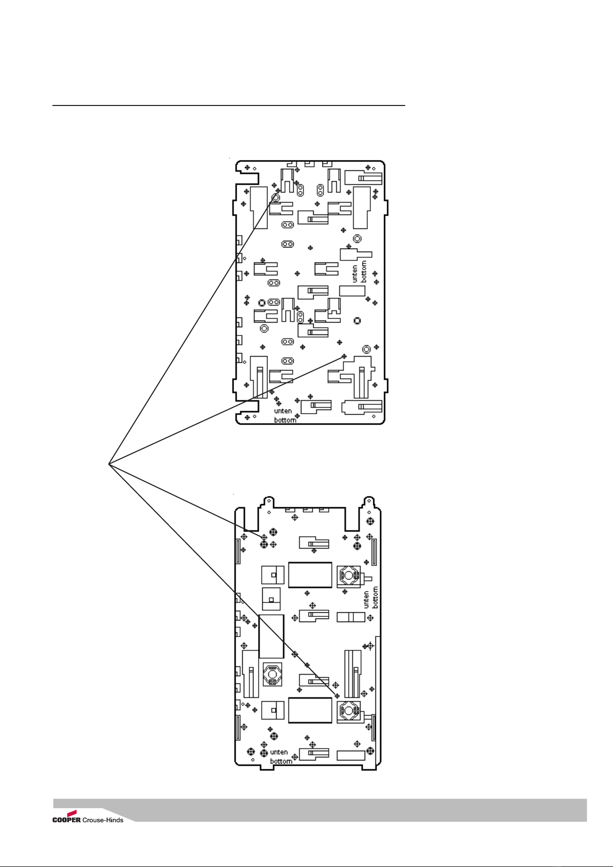
Gerätehalter für Gitterrinnen- und Wand-
befestigung
Gerätehalter für Rohrbefestigung
Explosionsgeschützte Steuergeräte GHG 43.
Befestigungs-
löcher für
Steuergerät
GHG 432
Befestigungslöcher auf Gerätehalter Größe
2Zur Sicherstellung der erforderlichen Mindest-
schutzart sind die Deckelschrauben fest
anzuziehen.
Bei übermäßigem Anziehen kann die
Schutzart beeinträchtigt werden.
Die für die eingesetzten KLE maßgebenden
Montagerichtlinien sind zu beachten.
Eigensichere Stromkreise sind über die
farblich (hellblau) gekennzeichneten KLE
einzuführen.