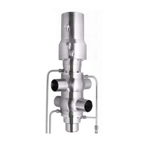
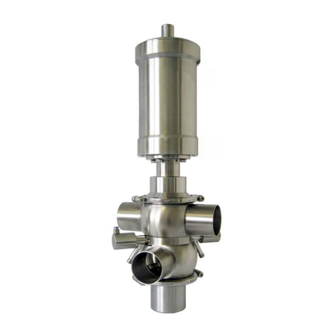
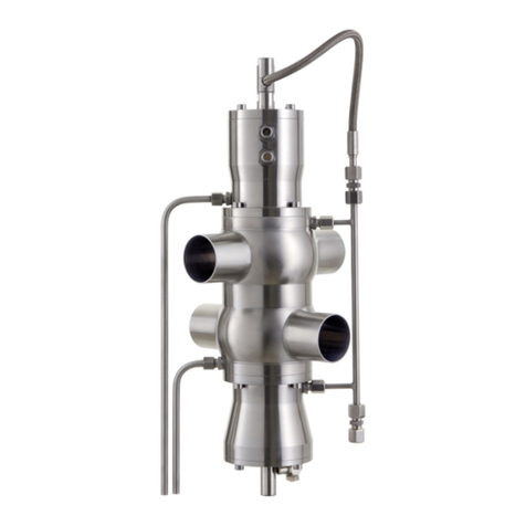
handtmann 33501 User manual

Translation
Operating manual
Safety relief valves
33501, 33502, 33503, 33521,
33601, 33602, 33603, 33621
BA(k)_033501.06_EN

BA(k)_033501.06_EN
2 / 30 Albert Handtmann Armaturenfabrik GmbH & Co. KG 2023-07-27
The Handtmann Armaturenfabrik can look back over a
long and successful tradition. Today it is part of the
globally operating Handtmann Group of Companies.
The Handtmann Armaturenfabrik is one of the leading
suppliers of armatures, valves and processing plants
for the beverage industry, and increasingly for
biotechnology and the chemical-pharmaceutical
industry.
The success of the Handtmann Armaturenfabrik is
based on long-term experience and processing
expertise, practice-oriented consultation,
comprehensive engineering work and state-of-the-art
production
The ambitious goals can only be realised with highly
qualified and motivated employees. This is why our
employees are at the heart of what Handtmann does.
The Handtmann Armaturenfabrik is not looking for short-
term success but rather the establishment of a long-term
partnership with customers.
© 2023
Albert Handtmann Armaturenfabrik GmbH & Co. KG
Arthur-Handtmann-Straße 11
88400 Biberach an der Riss
Germany
Tel.: +49 7351 342-0
Fax: +49 7351 342-4480
www.handtmann.de
Any copyrights regarding this technical documentation and
any drawings submitted to the receiver in person shall
remain at all times with
Albert Handtmann Armaturenfabrik GmbH & Co. KG,
Biberach, Germany.
They must not be copied nor reproduced without prior
written authorisation.
Handtmann Worldwide -
Technology for a Prosperous Future

Safety relief valves
33501, 33502, 33503, 33521, 33601, 33602, 33603, 33621
Foreword
BA(k)_033501.06_EN
2023-07-27 Albert Handtmann Armaturenfabrik GmbH & Co. KG 3 / 30
0Foreword ..........................................................................................................................................................5
1General.............................................................................................................................................................6
1.1 Manufacturer.....................................................................................................................................................6
1.2 Proper application .............................................................................................................................................6
1.3 Improper application .........................................................................................................................................6
1.4 Duties of operator..............................................................................................................................................6
2Safety Information............................................................................................................................................7
2.1 Symbols..............................................................................................................................................................7
2.2 Hazards and Safety Instructions ........................................................................................................................7
3Notes ................................................................................................................................................................9
3.1 Notes on transport.............................................................................................................................................9
3.2 Instructions for Delivery and Performance......................................................................................................10
3.3 Storage Instructions.........................................................................................................................................10
4Technical Description......................................................................................................................................11
4.1 Technical Data..................................................................................................................................................11
4.2 Identification of components .......................................................................................................................... 12
4.3 Valve types.......................................................................................................................................................13
5Perfomance Data ............................................................................................................................................14
6Operation .......................................................................................................................................................16
6.1 Valve actuator..................................................................................................................................................16
6.2 Valve Tightness / Leak ..................................................................................................................................... 16
6.3 Operating Characteristics ................................................................................................................................17
6.4 Valve cleaning / CIP.......................................................................................................................................... 17
7Disassembly....................................................................................................................................................18
7.1 Assembly instructions......................................................................................................................................18
7.2 Disassembling manual safety relief valves - Types 33501, 33502, 33503, 33521 ...........................................19
7.3 Disassembling pneumatic safety relief valves - Types 33601, 33602, 33603, 33621 ......................................19
8Installation and Commissioning......................................................................................................................21
8.1 Installation Instructions ................................................................................................................................... 21
8.2 Assembly.......................................................................................................................................................... 22
9Trouble shooting.............................................................................................................................................23
10 Maintenance...................................................................................................................................................24
10.1 Maintenance....................................................................................................................................................24
10.2 Inspection and Maintenance Intervals ............................................................................................................24
10.3 Function Checks............................................................................................................................................... 25
10.4 Seals.................................................................................................................................................................26
10.5 Spare parts.......................................................................................................................................................27
11 Additional Equipment.....................................................................................................................................28
11.1 Heating insets .................................................................................................................................................. 28
12 Disposal ..........................................................................................................................................................29

Safety relief valves
33501, 33502, 33503, 33521, 33601, 33602, 33603, 33621
Foreword
BA(k)_033501.06
4 / 30 Albert Handtmann Armaturenfabrik GmbH & Co. KG 2023-07-27

Safety relief valves
33501, 33502, 33503, 33521, 33601, 33602, 33603, 33621
Foreword
BA(k)_033501.06_EN
2023-07-27 Albert Handtmann Armaturenfabrik GmbH & Co. KG 5 / 30
0Foreword
These instructions contain instructions, notes and advice worth knowing, which are
necessary for the installation and/or operation.
Read the instructions to ensure trouble-free operation.
The technical data, descriptions and design specifications correspond to the state at the
time of printing. Intermediate design changes are possible in the interest of continuous
further development.
Pictures and drawings shown are only complete to the extent that they are required for
understanding.
The instructions serve to inform the operating personnel, the operator and, if applicable,
trained qualified personnel. The instructions are part of the system delivery. Removing
chapters from these instructions is prohibited. Missing instructions or missing pages
thereof must be replaced immediately.
Any person who is instructed to set up, commission, operate, maintain and repair the
system is required to read these instructions, specifically the safety notes, and have an
understanding of its content and language.
If necessary, internal instructions under consideration of the technical qualification of the
respective personnel must be provided.
To prevent operating errors and ensure the correct performance of necessary testing
measures, the instructions must be accessible to operating personnel at all times.
Handtmann Armaturenfabrik GmbH & Co. KG is not liable for damages and malfunctions
resulting from non-compliance with these instructions.

Safety relief valves
33501, 33502, 33503, 33521, 33601, 33602, 33603, 33621
General
BA(k)_033501.06
6 / 30 Albert Handtmann Armaturenfabrik GmbH & Co. KG 2023-07-27
1General
1.1 Manufacturer
Albert Handtmann Armaturenfabrik GmbH & Co. KG
Arthur-Handtmann-Str. 11; D-88400 Biberach
Tel.: +49(0) 73 51/3 42-0; Fax: +49(0) 73 51/ 3 42-44 80
E-Mail: sales.fittings@handtmann.de
1.2 Proper application
•Safety relief valves protect a pressurized system (tanks, containers, pipelines)
against impermissible pressure exceedance.
•Safety relief valves may be used for the intended purpose only. In this case, special
attention must be paid to the permissible pressure and temperature ranges, the
type of fluids to be discharged and the installation situation.
•Safety relief valves are intended for application in the beverage and food
processing as well as in the chemical-pharmaceutical industries.
•Safety relief valves are subject to the Pressure Equipment Directive 2014/68/EC.
•Safety relief valves comply with the requirements of DIN EN ISO 4126-1.
1.3 Improper application
Improper use is considered if:
•there are different operating conditions or uses than those intended for the type,
•unauthorized changes or modifications are made to the
component/assembly/plant,
•unqualified personnel carry out installation, operation and maintenance,
•shut-off devices are installed in front of the safety valves, which can then override
them,
•instructions in the operating instructions are not observed.
Improper use will result in the loss of any warranty services as well as statutory liability
claims.
1.4 Duties of operator
The operator must ensure in particular that
•the component/assembly/plant is operated in accordance with its intended
purpose and in correct functional condition.
•the legal requirements for operation and maintenance are observed.
•only sufficiently qualified authorised personnel performs maintenance on the
component/assembly/plant.
•the personnel responsible for operation and maintenance is familiar with and
observes the operating and assembly instructions and particularly the safety
instructions contained in them.
•the attached safety and warning signs are not removed and remain legible.

Safety relief valves
33501, 33502, 33503, 33521, 33601, 33602, 33603, 33621
Safety Information
BA(k)_033501.06_EN
2023-07-27 Albert Handtmann Armaturenfabrik GmbH & Co. KG 7 / 30
2Safety Information
2.1 Symbols
DANGER
Danger - endangerment caused by product-specific and process-specific conditions!
This symbol identifies an extremely dangerous situation that may result in severe bodily
injury or even death if the relevant safety instructions are disregarded.
WARNING
Warning –general dangers!
This symbol identifies dangerous situations that may result in light to severe bodily
injury if the relevant safety instructions are disregarded.
CAUTION
Caution –damage to components!
This symbol points out that special care must be taken during installation, operation or
maintenance.
NOTICE
Note
This symbol refers to issues requiring special attention.
NOTICE
Note
This symbol identifies an environmentally friendly procedure or disposal
method.
2.2 Hazards and Safety Instructions
Endangerment to service personnel
Explanations
Measures
Squeezing danger for fingers, hands and feet
Unintentional opening and closing of the safety relief
valve must be prevented during maintenance work.
•Disconnect the pneumatic connection with the
safety valve.
•Do not reach into the seat area of the valve disk
with your hands.
The safety relief valve can weigh several kilograms.
•Secure the valve against slipping and falling during
assembly, disassembly and in maintenance work.
Shock and impact danger

Safety relief valves
33501, 33502, 33503, 33521, 33601, 33602, 33603, 33621
Safety Information
BA(k)_033501.06
8 / 30 Albert Handtmann Armaturenfabrik GmbH & Co. KG 2023-07-27
Before taking out the upper valve part and loosening the
screws, the safety valve must be lifted manually or
pneumatically.
•Turn the counter nut on the valve rod by 2-3
rotations against the valve housing or apply
compressed air to the valve actuator.
Danger of thermal burns, chemical burns and scalding
If the safety relief valve in a system is operated with hot
media, the surface temperature of the safety valve can
also reach this value.
•Make sure that the piping system has cooled to a
value below 50°C.
•Attach warning signs (W026) for hot surfaces.
•The piping area in question must be sealed off from
the rest of the piping system.
When discharging fluid from the safety relief valve, there
is a risk of burns, scalding or chemical burns for the
operating and service personnel.
•Make sure that the fluids are discharged properly
and safely (exhaust line).
•Make sure that the valve is not opened in an
uncontrolled manner during maintenance work.
Chemical burns
If the safety valve in a system is operated with acidic or
alkaline media, your hands and fingers may suffer
chemical burns when disassembling the valve.
•Before removing the safety relief valve, check which
fluid the piping was conducting. If necessary, rinse
the piping again beforehand with water.
•Check the system pressure before removing the
safety relief valve.
Malfunction due to incorrect handling
Explanations
Measures
The valve must be switched off in the case of noticeable
malfunctions.
•Faults must be eliminated immediately.
The switching process of the valve is faulty or takes place
jerkily.
•Remove residues or loose small parts from the valve
seat area.
•Ventilate the valve periodically to prevent jamming
of the seat sealing (clean seat).
If the valve is not checked or maintained at regular
intervals, this can lead to malfunction or major functional
disruption.
•Check the valve during operational maintenance
cycles.
•Inspection and maintenance work should only be
carried out by qualified staff.
Malfunction through improper use
The range of application of the valve is intended for
specific operating states (pressure, temperature, media).
•Ensure proper use.
Installation of faulty or non-specified parts or using the
same as replacement parts may disable or disrupt
functionality considerably.
•Only use parts approved by the manufacturer.

Safety relief valves
33501, 33502, 33503, 33521, 33601, 33602, 33603, 33621
Notes
BA(k)_033501.06_EN
2023-07-27 Albert Handtmann Armaturenfabrik GmbH & Co. KG 9 / 30

3Notes
3.1 Notes on transport
DANGER
Danger - Danger of injury to persons!
There is a risk of accident during transport due to the high weight.
–Do not walk or stand under suspended loads.
–When unloading the assembly, always use inspected and approved lifting gear
(e.g., forklift truck, pallet truck, crane) and suitable aids with a sufficient load
carrying capacity.
–Shackles, e.g., in accordance with DIN 82101
–Lashing chains, e.g., in accordance with DIN 5687 quality class 8
–Transport must be performed only by instructed personnel.
CAUTION
Warning - General dangers
The danger areas must be cordoned off during transport and assembly (barrier tape).
ATTENTION
Note
Observe the information signs for transport.
Fig.
1
: Transport signs

Safety relief valves
33501, 33502, 33503, 33521, 33601, 33602, 33603, 33621
Notes
BA(k)_033501.06
10 / 30 Albert Handtmann Armaturenfabrik GmbH & Co. KG 2023-07-27
3.2 Instructions for Delivery and Performance
•Check the delivery note data for factual correctness.
•Check the delivery for completeness. Later complaints will not be accepted.
•Perform visual inspection of the packaging system for external transport damage.
These must be reported to the forwarder immediately.
•Claims due to transport damage not visible right away must be made within a week.
3.3 Storage Instructions
•The goods should remain in the delivered packaging systems until assembly.
•The goods must be stored in dry, closed rooms. Exposure to UV radiation and direct
sunlight must be avoided. The maximum moisture must not exceed 60 %; the
maximum storage temperature must not exceed 40 °C.
•It is vital to read the manual after unpacking the goods and before assembly.

Safety relief valves
33501, 33502, 33503, 33521, 33601, 33602, 33603, 33621
Technical Description
BA(k)_033501.06_EN
2023-07-27 Albert Handtmann Armaturenfabrik GmbH & Co. KG 11 / 30
4Technical Description
4.1 Technical Data
Valve data
Type
Safety relief valve
Type of functioning
Opens with pressure/closes with spring force
Order code
335xx/336xx
Product range
Materials
Stainless steel 1.4404
Seals
EPDM, optionally FKM/FPM (all FDA proof)
Surface
≤ 0.8 µm
Other parts
Materials
Stainless steel 1.4301, 1.4307
Seals
EPDM
Surface
Precision-turned, matte
Production / CIP
Applications
Free outflow
Fluids (nontoxic)
Fluids/gases/vapours (Group II, PED 2014/68/EU)
Readily commercially-available CIP cleaning media with 2-4
% lye/acid
Performance data
Performance data within 10 % pressure increase
Operating pressure
PS min/max 0/10 bar-g
Temperature
TS min/max 0/140 °C
Control air pressure
5 –7 bar, compressed air connection Ø 6/4 mm

Safety relief valves
33501, 33502, 33503, 33521, 33601, 33602, 33603, 33621
Technical Description
BA(k)_033501.06
12 / 30 Albert Handtmann Armaturenfabrik GmbH & Co. KG 2023-07-27
4.2 Identification of components
All safety relief valves are marked with a nameplate and a marking on the housing.
Marking of the nameplate
(The values on the nameplate shown below are example values.)
Marking of the housing
AH / DNXX / PNXX / T 0°C - 140°C / 1.4404 / Heat no.

Safety relief valves
33501, 33502, 33503, 33521, 33601, 33602, 33603, 33621
Technical Description
BA(k)_033501.06_EN
2023-07-27 Albert Handtmann Armaturenfabrik GmbH & Co. KG 13 / 30
4.3 Valve types
Type
Lifting
man pneu
Fluids
Nominal size
per type [DN]
Set pressure
[bar-g]
Counterforce
Installation
position
Weight
[kg]
33501, 33521
X
F/D/G
15 - 80
0.5 - 10.0
Pressure
spring
standing or
2.5 - 28.0
33601, 33621
x
F/D/G
15 - 80
0.5 - 10.0
horizontal
2.5 - 28.0
33502
X
F/D/G
50
0.5 - 10.0
Pressure
spring
standing or
13.0 - 21.0
33602
X
50
0.5 - 10.0
horizontal
33503
X
F/D/G
40 - 80
0.5 - 10.0
Pressure
spring
standing or
9.0 - 28.0
33603
X
F/D/G
40 - 80
0.5 - 10.0
horizontal
9.0 - 28.0
Notes
–Fluids (F), air/gases (G), steam (D)
–Lifting: Manual (man) or pneumatic (pneu)
–Type: 33502/33602 with proportional opening characteristic
–Type: 33503/33603 with hygienic connecting flange integrated in housing
–Type: 33521/33621 with adjustable pressure range and scaling
–Sealing material: EPDM / optionally FKM (FPM)
Optional equipment
–Scaling and restraint
–Heating cartridges, plugging, proximity switch

Safety relief valves
33501, 33502, 33503, 33521, 33601, 33602, 33603, 33621
Perfomance Data
BA(k)_033501.06
14 / 30 Albert Handtmann Armaturenfabrik GmbH & Co. KG 2023-07-27
5Perfomance Data
Fluid: Air
33501/33521/33601/33621
33501/33503/33521/33601/33603/33621
Pressure
[bar-g]
Throughput [Nm³/h]
DN 15
DN 25
DN 40
DN 50
DN 65
DN 80
1
137
369
736
1.054
1.917
3.035
2
208
560
1.119
1.603
2.915
4.615
3
279
752
1.502
2.152
3.913
6.195
4
210
944
1.885
2.701
4.911
7.775
5
253
1.136
2.268
3.250
5.909
9.355
6
295
1.328
2.651
3.799
4.107
10.935
7
338
1.520
3.034
4.348
4.700
7.196
8
380
1.711
3.417
4.896
5.293
8.105
9
423
1.903
3.800
5.445
5.887
9.013
10
466
2.095
4.183
5.994
6.480
9.922
Fluid: Water
33501/33521/33601/33621
33501/33503/33521/33601/33603/33621
Pressure
[bar-g]
Throughput [kg/h]
DN 15
DN 25
DN 40
DN 50
DN 65
DN 80
1
3.970
10.760
26.012
42.430
65.910
107.260
2
5.610
15.210
36.790
60.010
93.210
151.690
3
6.870
18.630
45.050
73.490
114.160
167.210
4
7.940
21.520
52.030
84.860
131.820
193.080
5
8.870
24.060
58.160
94.870
147.370
215.870
6
9.720
26.370
63.710
103.940
161.450
236.470
7
10.500
28.460
68.820
112.260
174.380
255.420
8
11.220
30.440
73.570
120.010
186.420
273.060
9
11.900
32.290
78.040
127.290
197.730
289.620
10
12.540
34.040
82.260
134.180
208.420
305.290

Safety relief valves
33501, 33502, 33503, 33521, 33601, 33602, 33603, 33621
Perfomance Data
BA(k)_033501.06_EN
2023-07-27 Albert Handtmann Armaturenfabrik GmbH & Co. KG 15 / 30
Fluid: Steam
33501/33521/33601/33621
33501/33503/33521/33601/33603/33621
Pressure
[bar-g]
Throughput [kg/h]
DN 15
DN 25
DN 40
DN 50
DN 65
DN 80
1
56
255
518
709
1.294
2.297
2
85
387
788
1.078
1.967
3.143
3
117
520
1.058
1.447
2.640
4.219
4
147
653
1.327
1.816
3.314
5.295
Fluid: Water
Fluid: Air
Fluid: Steam
33502/33602
Pressure
Throughput
[kg/h]
Pressure
Throughput
[Nm³/h]
Pressure
Throughput
[kg/h]
[bar-g]
DN 50
[bar-g]
DN 50
[bar-g]
DN 50
1
18.628
1
527
1
401
2
26.344
2
802
2
603
3
32.265
3
1.076
3
801
4
37.257
4
1.351
4
1.000
5
41.654
5
1.625
---
---
6
45.630
6
1.900
---
---
7
49.286
7
2.174
---
---
8
52.689
8
2.449
---
---
9
55.885
9
2.723
---
---
10
58.908
10
2.998
---
---

Safety relief valves
33501, 33502, 33503, 33521, 33601, 33602, 33603, 33621
Operation
BA(k)_033501.06
16 / 30 Albert Handtmann Armaturenfabrik GmbH & Co. KG 2023-07-27
6Operation
WARNING
Warning –General hazards!
If the pressure system is exposed to a higher fluid temperature, the surface
temperature of the assembly can reach this value as well.
–Attach warning signs for hot surfaces.
CAUTION
Caution - Damage to components!
If the valve is not checked and serviced at certain intervals, the function may be
overridden or significantly disturbed.
–It is recommended to carry out regular checks.
6.1 Valve actuator
•Safety relief valves protect a pressurised system against impermissible pressure
exceedance.
•Fluids (F), gases (G) and vapours (D) can be discharged via the safety relief valves.
•During normal operation the safety relief valve should not be activated / opened.
(Always ensure sufficient allowance between the operating pressure and the set
pressure).
•Safety relief valves open within an opening pressure difference of 10 % of the
response pressure. At a response pressure of < 1 bar, the opening pressure
difference can be up to 0.1 bar. The specified exhaust performance is achieved
here.
•The lifting itself can be performed according to the process requirements. The
duration of lifting should be about 5-20 seconds and can take place during different
cleaning steps. Lifting takes place during the startup phase of the pump with
reduced power.
6.2 Valve Tightness / Leak
If the area of the valve seat is not sealed properly (seal defective, foreign object trapped,
valve disk lifted manually, spring broken), the valve will exhaust in normal position (valve
closed).
This also results in pressure not being built up or only with difficulty in a pressurized
system.
Note
Heed the pressure difference between operating pressure and response pressure!

Safety relief valves
33501, 33502, 33503, 33521, 33601, 33602, 33603, 33621
Operation
BA(k)_033501.06_EN
2023-07-27 Albert Handtmann Armaturenfabrik GmbH & Co. KG 17 / 30
6.3 Operating Characteristics
•All the safety relief valves are checked ex works and set to the required pressure.
The setting or the set value is documented in a setting test log.
•The pressure setting occurs at ambient pressure.
•A change of the set pressure is prevented through positive locking inside the upper
valve part. An optional lead sealing provides an additional safety measure on the
outside.
CAUTION
Caution –functional impairment or material damage!
Mechanical manipulations may cause malfunctions.
–Mechanical modifications to the safety relief valves that influence the set
pressure or functionality are impermissible.
–Required modifications should only be carried out by the manufacturer.
Operating pressure:
Working pressure under normal operating conditions
(lower than set pressure)
Set pressure:
Excess pressure at which the safety relief valve starts opening
Response pressure:
Excess pressure at the safety relief valve starts opening during
operation (abnormal operating condition)
Closing pressure:
Pressure at which the safety relief valve is closed again
6.4 Valve cleaning / CIP
Safety relief valves should be cleaned within a defined time period.
•Manual safety relief valves must be disassembled.
The seat area and the seal are cleaned manually.
•Safety relief valves with pneumatic actuator are lifted via compressed air.
The seat area and the seal are cleaned within an automated CIP process.
The safety relief valve should be alternately opened and closed.
CAUTION
Caution –functional impairment or material damage!
Jamming hazard for valve seat/valve disk!
–If the safety relief valve opens upon tank overfilling, especially with viscous,
sugary media, the valve seat must always be cleaned.
Safety valves with pneumatic actuator can be opened for CIP cleaning. For this purpose, a
control air pressure of 5-7 bar are required independent of the set pressure.
Pneumatic connection G 1/8“ with plug connection for compressed air hose Ø 6/4 mm

Safety relief valves
33501, 33502, 33503, 33521, 33601, 33602, 33603, 33621
Disassembly
BA(k)_033501.06
18 / 30 Albert Handtmann Armaturenfabrik GmbH & Co. KG 2023-07-27
7Disassembly
7.1 Assembly instructions
Before starting work:
•Read the operating instructions and, in particular, the safety information.
•Check the current system status, e.g., pressure, temperature, medium,
operating status.
•Clean, empty and/or depressurise the piping system.
•Disconnect pneumatic and electric connections from the actuator.
CAUTION
Caution –damage to components!
Installation of faulty or non-specified parts or using the same as replacement parts may
disable or disrupt functionality considerably.
–Only use parts and equipment approved by the manufacturer.
–After the work has been carried out, the function of the valve must be checked.
WARNING
Warning –Welding hazards!
When dismantling valves or setting up a system, pipes must be welded. This can lead to
a fire. The fire can seriously injure people.
During disassembly/assembly, sharp-edged pipe ends may be present. The staff can cut
themselves at the sharp edges.
Welding or cutting pipes creates hot surfaces. These can lead to burns.
Therefore, please note the following before welding:
–Welding work may only be carried out by qualified personnel.
–Remove all flammable parts from the environment before welding.
–Cover combustible parts that cannot be removed.
–Prior to commencement of flame, welding, soldering and/or grinding operations,
approval must be obtained from the plant manager for open fire/welding work.
–Work only with a release certificate.
–Have fire extinguishing agents, e.g. powder extinguishers ready.
–Organize fire stations.
–Check the workplace for fire nests several times up to 24 hours after completion
of the work.
–Wear personal protective clothing during welding.
•cut-resistant, heat-resistant hand protection
•Foot protection
•Head protection

Safety relief valves
33501, 33502, 33503, 33521, 33601, 33602, 33603, 33621
Disassembly
BA(k)_033501.06_EN
2023-07-27 Albert Handtmann Armaturenfabrik GmbH & Co. KG 19 / 30
7.2 Disassembling manual safety relief valves - Types 33501, 33502, 33503, 33521
A B
A) Turn lifting nut (1) against the actuator, add two further turns.
B) Remove the screws (3), extract the upper part of the valve (4).
C D
C) Screw on valve disc (1).
D) Replace the seals (4) of the housing inset (5) and the valve disk (6).
7.3 Disassembling pneumatic safety relief valves - Types 33601, 33602, 33603, 33621
A B
A) Remove the cap nut (2), turn lifting nut (1) against the actuator, add two further turns.
B) Remove the screws (3), remove the lifting nut, extract the upper part of the valve (4).
2
1
2
1
4
4
3
4
1
2
4
4
5
3
6
3

Safety relief valves
33501, 33502, 33503, 33521, 33601, 33602, 33603, 33621
Disassembly
BA(k)_033501.06
20 / 30 Albert Handtmann Armaturenfabrik GmbH & Co. KG 2023-07-27
C D
C) Remove the pressure spring and securing ring (1), remove spring pressure disc (2).
D) Remove screws (5), remove pneumatic drive (4), loosen inside screws (3) and remove flange
(only with large nominal sizes DN 50, 65, 80), remove housing insert with valve rod.
E F
E) Pull lifting piston (3) from piston guide (1), replace seals (2).
F) Screw on valve disk, replace seals (4) for housing insert (5) and valve disk.
4
1
2
2
3
2
4
4
1
4
5
3
A
B
C
5
This manual suits for next models
7
Table of contents
Other handtmann Control Unit manuals

handtmann
handtmann 12504 User manual

handtmann
handtmann 12012 User manual

handtmann
handtmann 12501 User manual

handtmann
handtmann 12503 User manual

handtmann
handtmann 12605 User manual

handtmann
handtmann FLOWmag 12020 User manual

handtmann
handtmann INOVA User manual

handtmann
handtmann 75100 User manual

handtmann
handtmann 491 User manual
Popular Control Unit manuals by other brands

Krom Schroder
Krom Schroder PFU 780 technical information

Sferalabs
Sferalabs Strato Pi SPTM20XP user guide

Sel
Sel M8100.0060 user manual

Qcells
Qcells Q.PEAK DUO M-G11 Series Installation and operation manual

Alfalaval
Alfalaval Unique 7000 Series instruction manual

GiBiDi
GiBiDi SC230 electrical connections