Types 2506, 2516, 2516F
10
Startup
It is important that the output range of the transmitter
or other device used as the input to the receiver/con-
troller be adjusted so that its output range corresponds
to the input signal range of the receiver/controller. Be
sure the receiver/controller action (direct or reverse) is
correct for the application.
To start the system:
DFor all receiver/controllers, perform steps 1
and 2.
1. See table 3 for specific pressure limits. Be sure the
correct supply pressure is available. If necessary, ad-
just the regulator to 20 psig (1.4 bar) for a 3 to 15 psig
(0.2 to 1 bar) or 35 psig (2.4 bar) for a 6 to 30 psig
(0.4 to 2 bar) receiver/controller range.
2. Turn on the supply pressure to the receiver/control-
ler.
DTo make the proper level or output pressure
setting for a Type 2506 receiver/controller, go to
step 3. To make the proper level or output pres-
sure setting for a Type 2516 receiver/controller, go
to step 9. For the Type 2506 receiver/controller:
3. Set the proportional band adjustment at 15 percent
(1.5 on the adjustment dial). At this setting, a 1.8 psig
(0.1 bar) input pressure causes a 12 psig output pres-
sure change. Operate the receiver/controller with the
proportional band setting as small as possible.
4. Provide an input pressure equal to the output pres-
sure of the transmitter at a value desired or halfway
between the transmitter output range. For example, on
a receiver/controller, if the desired control point is half-
way between the ends of the displacer, provide an in-
put of 9 psig (0.6 bar) which is halfway between 3 and
15 psig (0.2 and 1 bar) transmitter output range.
5. Set the output pressure adjustment to give a con-
troller output that is halfway between its output range.
6. Vary the input pressure to be sure the full controller
output pressure range is produced within the specified
input pressure range.
7. Lock the output pressure adjustment and connect
the receiver/controller to the final control element.
8. If the proportional band setting is too narrow, caus-
ing instability, widen the proportional band just enough
to stabilize control. After making this adjustment, it
may be necessary to reset the output pressure slightly
to produce the proper control range.
DFor the Type 2516 receiver/controller:
9. Set the proportional band adjustment dial at 0 per-
cent (minimum proportional band).
10. Set the reset adjustment to the fastest speed
(0.005 minutes-per-repeat).
11. Provide an input pressure equal to the output
pressure of the transmitter at a value desired or half-
way between the transmitter output range. For exam-
ple, on a receiver/controller, if the desired control point
is halfway between the ends of the displacer, provide
an input of 9 psig (0.6 bar) which is halfway between 3
and 15 psig (0.2 and 1 bar) transmitter output range.
12. Adjust the output pressure dial to give a controller
output somewhere within the output range of the re-
ceiver/controller.
13. Lock the output pressure dial and connect to the
final control element.
14. If the proportional band is too narrow causing in-
stability, widen the proportional band or slow the reset
just enough to stabilize control.
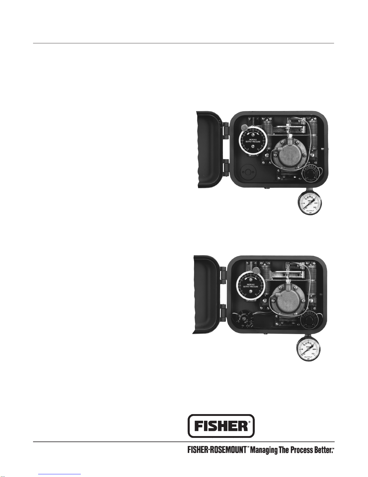
Adjustments
To adjust the receiver/controller, open the cover and
locate the appropriate adjustment. See figures 15, 18,
19 for the location of adjustments.
Set Point Adjustment
To adjust the level set point, loosen the knurled knob
and rotate the knob around the INCREASE OUTPUT
PRESSURE or RAISE LEVEL dial. To raise fluid or
interface level or increase density, rotate the knob in
the direction of the arrow.
To lower level or decrease density, rotate the knob in
the opposite direction. The INCREASE OUTPUT
PRESSURE or RAISE LEVEL dial is graduated (in
percent) to show approximate indications of the receiv-
er/controller set point. When making adjustments, do
not rely only on the dial setting. Monitor the process
fluid level to be sure the receiver/controller attains the
desired set point.
For differential gap receiver/controllers, the level set-
ting adjustment determines the location of the gap
within the range of the sensing element.
Remote Set Point Adjustment
On a receiver/controller with remote set point adjust-
ment capability, adjust the set point by changing the
pressure to the remote set point connection. Increase
the remote set point signal pressure to decrease the
receiver/controller set point (for a direct acting receiv-
er/controller) or increase the receiver/controller set
point (for a reverse acting receiver/controller).