Fisher 304 User manual

D200106X012
Fisher Controls International, Inc. 1987, 1996; All Rights Reserved
Fisher, Fisher-Rosemount, and Managing The Process Better are marks owned
by Fisher Controls International, Inc. or Fisher-Rosemount Systems, Inc.
All other marks are the property of their respective owners.
Type
3
0
4 a
n
d 3
04
L E
lectrica
l
Positio
n S
witch
Contents
Introduction
1.
. . . . . . . . . . . . . . . . . . . . . . . . . . . . . .
Scope of Manual 1.
. . . . . . . . . . . . . . . . . . . . . . . . . . .
Description 1
. . . . . . . . . . . . . . . . . . . . . . . . . . . . . . . . .
Specifications 1
. . . . . . . . . . . . . . . . . . . . . . . . . . . . . .
Installation
3
. . . . . . . . . . . . . . . . . . . . . . . . . . . . . . . .
Mounting the Position Switch on the Actuator 3.
. .
Mounting the Position Switch on
Other Devices 4.
. . . . . . . . . . . . . . . . . . . . . . . . . . . . .
Electrical Connections 5.
. . . . . . . . . . . . . . . . . . . . . .
Adjustment
6
. . . . . . . . . . . . . . . . . . . . . . . . . . . . . . .
Principle of Operation
6.
. . . . . . . . . . . . . . . . . .
Maintenance
7
. . . . . . . . . . . . . . . . . . . . . . . . . . . . . .
Parts Ordering
8.
. . . . . . . . . . . . . . . . . . . . . . . . . . .
Parts List
8.
. . . . . . . . . . . . . . . . . . . . . . . . . . . . . . . .
Position Switch Common Parts 8.
. . . . . . . . . . . . . .
Terminal Strip Assembly 8.
. . . . . . . . . . . . . . . . . . . .
Position Switch Mounting Parts 8.
. . . . . . . . . . . . . .
Additional Actuator Parts for Field Mounting 22.
.
Introduction
Scope of Manual
This instruction manual provides installation, adjust-
ment, maintenance, and parts ordering information for
the Type 304 and 304L electrical position switches.
This manual also provides ordering information for the
hardware used to mount the switches on Fisher actua-
tors.
Figure1. Type 304 Electrical Position Switch with
Cover Removed
W5939 / IL
Only personnel qualified through training or experience
should install, operate, and maintain these position
switches. If you have any questions concerning these
instructions, contact your Fisher Controls sales office
or sales representative before proceeding.
Description
The Type 304 and 304L switches are normally
mounted on a control valve actuator to operate
alarms, signal lights, relays, solenoid valves, or other
equipment when valve travel reaches predetermined
points.
The Type 304 position switch (see figure 1) is for ap-
plications that require only one or two switches. The
Type 304L position switch is for applications that re-
quire three or more switches with a maximum of six
switches (see figure 3). The individual switches can be
adjusted to operate at any point of travel within the 90
degrees of cam rod rotation.
Specifications
Specifications for the Type 304 and 304L electrical
position switches are listed in table 1.
Instruction Manual
Form 2007
October 1996 Type 304 & 304L

Type 304 & 304L
2
Table 1. Specifications
Available Configurations
Type 304: Unit contains 1 or 2 switches
Type 304L: Unit contains 3, 4, 5, or 6 switches
Maximum Cam Rotation
90 degrees between point of actuation of first switch
and point of actuation of last switch
Switch Type
Single-pole, double-throw
Switch Electrical Ratings
Service Ratings (when wired at the factory): See
tables 2 and 3
Maximum Continuous Current: 20 amperes
Maximum Inrush Current: 30 amperes with normal-
ly-closed contacts; 25 amperes with normally-open
contacts
Electric Motor Rating: Capable of switching a 3/4
horsepower electric motor at 125 V ac or a 1-1/2
horsepower motor at 250 V ac
Hazardous Area Classification
Refer to the Hazardous Area Classification bulletins
and the switch nameplate (see figure 2 for typical
nameplate)
Operating Temperature Range(1)
–40_to +180_F (–40_to +82_C)
Conduit Connection
With Bushing: 3/4-inch NPT female connection ac-
cepts a maximum of six 14-gauge wires
Without Bushing: 1-1/4 inch NPT female connection
accepts a maximum of eighteen 14-gauge wires
For Explosion Proof Installation: Appropriate con-
duit seal is required 18 inches (460 mm) from hous-
ing
Approximate Weight
Type 304 (with 2 switches and cover): 5 pounds
(2.3 kg)
Type 304L (with 6 switches and long cover): 10
pounds (4.5 kg)
Options
Terminal Strip
1. This term is defined in ISA Standard S51.1-1979
Table 2. Direct-Current Service Ratings
NON-INDUCTIVE INDUCTIVE
DIRECT
CURRENT
Heater Load Lamp Load (Tungsten) Motor, Relay, or Solenoid Load
DIRECT
CURRENT Normally Open
Contact Normally Closed
Contact Normally Open
Contact Normally Closed
Contact Normally Open
Contact Normally Closed
Contact
V
olts (DC)
Amperes Amperes Amperes Amperes Amperes Amperes
6-8
12-14
24-30
110-115
220-230
15
15
6
0.4
0.2
20
20
6
0.4
0.2
1.5
1.5
1.5
0.4
0.2
3
3
3
0.4
0.2
15
10
5
0.05
0.03
20
10
5
0.05
0.03
T
able 3. Alternating-Current Service Ratings
NON-INDUCTIVE INDUCTIVE
ALTERNATING
CURRENT
Heater Load Lamp Load (Tungsten) Motor, Relay, or Solenoid Load
ALTERNATING
CURRENT Normally Open
Contact Normally Closed
Contact Normally Open
Contact Normally Closed
Contact Normally Open
Contact Normally Closed
Contact
V
olts (AC)
Amperes Amperes Amperes Amperes Amperes Amperes
110-115
220-250
440-480
20
20
20
20
20
20
2.5
1.25
0.75
3
2.5
1
15
15
2.5
15
15
2.5

Type 304 & 304L
3
Table 4. Assembly Drawing References
ACTUATOR TYPE(1) SIZE FIGURE
NUMBER
329
350 Series
470
470
470
470 with
covered yoke
All
All
30
40 through 68
80 through 100
80
17
7
8
7
14
8
478
478-16
478-16
513 and 513R
585 and 585R
585C and 585CR
657 and 667
657 and 667 with
covered yoke
40 through 68
60 and 68
80 and 100
20 and 32
25, 50, and 100
25 and 50
30 and 34
40 through 70
7
9
14
10
11
12
13 and 15
13
657 and 667
657 and 667
1051, 1052, and 1061
1051 and 1052
1052
40 through 70
80 and 87
30, 40, 60, 68, and 70
33
20
7 and 15
7, 14, & 15
16
18
19
1061 and 1069
1066 and 1066SR
1076
1077
1078
1250 and 1250R
Additional field
mounting parts
80 and 100
20, 27, and 75
1, 2, and 3
0-, 2-, 6-, 7-, and 9-KE
A, AA, and AAA
225, 450, and 675
– – –
17
20
21
22
23
24
25
1. Contact your Fisher Controls sales office or sales representative for information for
mounting on actuator types and sizes not listed.
Installation
When Type 304 and 304L switches are ordered with
an actuator, the factory mounts the position switch and
adjusts the cams for the travel specified on the order.
When installation is complete, the cam adjustments
should be checked as described in the adjustment pro-
cedures.
If the position switch has been ordered separately, or
removed for maintenance, refer to the appropriate pro-
cedure for mounting.
Mounting the Position Switch on the
Actuator
To mount a Type 304 or 304L position switch on a
Fisher Controls actuator in the field, see the additional
actuator parts for field mounting section of the parts
list. These additional parts, plus those parts listed in
the position switch mounting parts section, are re-
quired for some actuators.
Refer to the appropriate actuator instruction manual
for procedures to disassemble and assemble actuator-
to-valve connections if required.
Figure2. T
ypical Nameplate with Hazardous Area
Classification Information
INFORMATION IN THIS PORTION OF THE
NAMEPLATE IDENTIFIES THE HAZARDOUS
AREA CLASSIFICATION AND APPROVALS
FOR THE PRODUCT SPECIFIED ON THE
EQUIPMENT ORDER.
11A4723–KSHT 1 / IL
WARNING
Avoid personal injury from sudden re-
lease of process pressure. Before disas-
sembly:
DDisconnect any operating lines pro-
viding air pressure, electric power, or a
control
signal to the actuator
. Be sure the
actuator cannot suddenly open or close
the valve.
DUse bypass valves or completely
shut off the process to isolate the valve
from process pressure. Relieve process
pressure from both sides of the valve.
Drain the process media from both sides
of the valve.
DUse lock-out procedures to be sure
that the above measures stay in effect
while you work on the equipment.
DVent the power actuator loading
pressure and relieve any actuator spring
precompression.
DFor 304 switches in intrinsically
safe
areas, current monitoring during opera-

Type 304 & 304L
4
Figure3. Location of Parts for T
ype 304L Position Switch
SWITCH
ROLLER
ADJUSTMENT
ROLLER
GEARED
NUT CAM
CAM EAR
GROUND
TERMINAL
BASE
W5940 / IL
tion must be with an approved meter for
hazardous
areas in order
to avoid person
-
al injury or property damage caused by an
explosion or fire.
WARNING
Refer to the appropriate actuator
instruction manual before removing the
actuator-to-valve connection. Personal
injury or property damage may result
from sudden release of preloaded
spring force.
Generally, the position switch is attached to the
mounting plate with machine screws, and the mount-
ing plate is installed on the actuator. Then, the con-
necting linkage or coupling between the actuator and
position switch is installed.
Refer to table 4 for references to the assembly draw-
ing figures that show typical installations of the posi-
tion switch.
After mechanically connecting the position switch to
the actuator, refer to the electrical connections and
operating information sections to place the position
switch in operation.
Mounting the Position Switch on Other
Devices
For other applications of the position switch, provide
suitable mounting hardware. If the motion of the moni-
tored device is linear, provide a lever arm to convert
the linear motion to rotary motion. The lever arm
should be limited to 90 degrees of rotation from the
point at which the first switch actuates. This ensures
that the first switch remains actuated until the input
motion is reversed.
If the motion of the monitored device is rotary, the
switch can be coupled directly to the device if the
rotary motion does not exceed 90 degrees from the
point at which the switch first actuates. If the rotary
motion of the device is greater than 90 degrees after
the first switch actuates, provide a gear and/or lever
arm to reduce the rotation to 90 degrees or less.
After connecting the switch to the device, refer to the
electrical connections and operating information proce-
dures to place the position switch in operation.

Type 304 & 304L
5
NOTES:
1. THE CIRCUIT DIAGRAM SHOWN WITH EACH CAM AND ROLLER IS THE INTERNAL CONNECTIONS WITHIN THE SWITCH. THE CIRCUIT IS SHOWN
SCHEMATICALLY, AND DOES NOT REPRESENT THE ACTUAL MECHANICAL DESIGN.
2. SWITCH TERMINAL DESIGNATIONS:
COM—STANDS FOR COMMON. ITIS THE COMMON CONNECTION POINT BETWEEN THE NC AND NO TERMINALS.
NC—STANDS FOR NORMALLY CLOSED CONTACTS. CONNECTION IS CLOSED BETWEEN THIS TERMINAL AND THE COM TERMINAL WHEN SWITCH IS
IN THE NORMAL CONDITION. CONNECTION IS OPEN (NO CONTACT) WHEN SWITCH IS ACTUATED
NO—STANDS FOR NORMALY OPEN CONTACTS. CONNECTION IS OPEN (NO CONTACT) BETWEEN THIS TERMINAL AND THE COM TERMINAL WHEN
SWITCH IS IN THE NORMAL CONDITION. CONNECTION IS CLOSED WHEN SWITCH IS ACTUATED.
3. TRIP POINT IS THE POINT AT WHICH THE SWITCH CHANGES FROM THE NORMAL CONDITION TO THE ACTUATED CONDITION, OR VICE VERSA.
SWITCH
HOUSING
TRIP POINT
NCNO COM
Figure
4. Standard Switching Conditions
Maximum
Clockwise
Shaft Rotation
Intermediate
Shaft Position Maximum
Counterclockwise
Shaft Rotation
Switch Set
to change
State at
maximum
counter-
clockwise
shaft
rotation
Switch
Set to
change
state at
maximum
clockwise
shaft
rotation
MARKED COM
MARKED NC
MARKED NO
TYPICAL SWITCH HOUSING(2)
CAM ROD
LINKAGE
CAM
ROLLER AND ARM
SWITCH CONDITION IN RELATION TO RIP POINT(3)
NCNO COM NCNO COM NCNO COM
NCNO COM
A6894 / IL
Electrical Connections
Make the required electrical connections through the
conduit connection in the base (figure 3). Use a suit-
able conduit connector for hazardous locations. If the
unit is equipped with an optional terminal strip, make
connections to the strip. If the unit does not have a
terminal strip, make connections directly to the individ-
ual switches. A ground terminal connection is provided
by the green wire retainer and screw in the base.
CAUTION
For explosion-proof applications, install
a suitable conduit seal no more than 18
inches (460 mm) from the position
switch. Personal injury or property dam-
age may result if seal is not installed.
To obtain a normally-closed circuit (the circuit for an
individual switch is closed until the switch is actuated),
wire to the C (common) and the NC (normally-closed)
terminals. To obtain a normally-open circuit (the circuit
for an individual switch is open until the switch is actu-
ated), wire to the C (common) and the NO (normally-
open) terminals.
Unless specified otherwise on the order, switch 1 (the
switch closest to the base) changes state (changes
from mornal to actuated) at the valve-closed position.
Unless otherwise specified, the switch farthest from
the base changes state (changes from normal to actu-
ated) at the valve fully open position. Refer to figure 4
for standard switching conditions.

Type 304 & 304L
6
NOTES:
SWITCHES ACTUATE AS ACTUATOR STEM TRAVELS
DOWN OR AS ROTARY VALVE SHAFT ROTATES COUNTERCLOCKWISE.
SWITCH FARTHEST FROM BASE ACTUATES AT FULLY
OPEN VALVE POSITION.
Figure5. Cam and Switch Details
42A0105–D
B1818–3/ IL
ACTUATOR STEM
UP
OPTIONAL SWITCHES
ARE SET AS REQUIRED SWITCH 1 ACTUATES AT VALVE
CLOSED POSITION
CAM ROD
BASE
TERMINAL STRIPS
ARE OPTIONAL
ROLLER
ADJUSTMENT SCREW
SMALL RADIUS
CAM HEEL
GEARED NUT
CAM EAR
3/8–INCH (9.5 mm) RADIUS
ROLLER
1/16 INCH
(1.6 mm)
ACTUATOR STEM
DOWN
2
1
1
2
Adjustment
WARNING
On an explosion-proof instrument, re-
move electrical power before removing
the instrument cover in a hazardous
area. Personal injury or property dam-
age may result from fire and explosion if
power is applied to the instrument with
the cover removed in a hazardous area.
1. Position the valve or monitored device at the point
of travel where actuation of a particular switch is de-
sired.
2. Open the circuits between the switch and power
supply, and remove the switch cover.
3. Refer to figure 3. Use a light or ohmmeter to indi-
cate switch actuation. Insert a screwdriver into the
geared nut of the appropriate switch and pry against
the cam ear. Rotate the cam until its small radius (see
figure 5) contacts the lever arm roller and actuates the
switch. Tension provided by a spring washer holds the
cam in place.
4. Always adjust the cams so that the small radius of
the cam actuates the switches. This minimizes the
differential travel (dead band) required to make and
then break the circuit. The switch should not actuate
on the heel of the cam; this increases the dead band.
5. To ensure switching at the open and closed valve
positions, set the switch to actuate approximately
1/32-inch (0.8 mm) before the valve reaches these
positions.
6. The lever arm roller is preset at the factory approxi-
mately 1/16-inch (1.5 mm) from the 3/8-inch (9.5 mm)
radius of the cam, as shown in figure 5. Adjust this
dimension by turning the adjustment screw on the
switch lever arm. Use the adjustment screw only to
position the lever arm in relation to the cam; do not
use the screw to adjust the point at which the switch
actuates.
7. Replace the cover (key 2).
Principle of Operation
When used with sliding-stem valves, the operating arm
(key 49, figure 7) converts linear valve travel to rotary
motion of the cam rod.
When used with rotary shaft valves, the coupler (key
105, figure 16) links the position switch and the rotary
actuator directly and rotates the cam rod.
As the cam rod rotates, cams mounted on the rod
contact the switch rollers and actuate the switches,
which opens or closes individual switch circuits.

Type 304 & 304L
7
As the actuator stem travels downward (for sliding-
stem valves) or as the valve shaft rotates counter-
clockwise (for rotary valves), the switch roller rides up
on the small radius of the cam lobe, actuates the
switch, and rests on the lobe during the remainder of
the travel. The normal or un-actuated position of the
switch is with the roller positioned over, but not touch-
ing, the 3/8-inch (9.5 mm) radius of the cam as shown
in figure 5.
Maintenance
WARNING
Avoid personal injury from sudden re-
lease of process pressure. Before disas-
sembly:
DDisconnect any operating lines pro-
viding air pressure, electric power, or a
control
signal to the actuator
. Be sure the
actuator cannot suddenly open or close
the valve.
DUse bypass valves or completely
shut off the process to isolate the valve
from process pressure. Relieve process
pressure from both sides of the valve.
Drain the process media from both sides
of the valve.
DUse lock-out procedures to be sure
that the above measures stay in effect
while you work on the equipment.
DVent the power actuator loading
pressure and relieve any actuator spring
precompression.
WARNING
For 304 switches in intrinsically safe
areas, current monitoring during must
be with an approved meter for hazard-
ous areas in order to avoid personal in-
jury or property damage caused by an
explosion or fire.
Refer to figure 6 for key number locations.
WARNING
On an explosion-proof instrument, re-
move electrical power before removing
the instrument cover in a hazardous
area. Personal injury or property dam-
age may result from fire and explosion if
power is applied to the instrument with
the cover removed in a hazardous area.
To replace switches, open the circuits between the
switch and power source, and unscrew the cover (key
2). Record the wire connections to the defective switch
or switches. Remove the hex nuts, lockwashers, and
end plate (keys 10, 8, and 9). Remove any spacers
(key 18). Disconnect the wires from the switches, and
slide the switches off the switch posts (key 4). After
replacing switches, attach the wires as recorded. Ad-
just the switch cams as described in the Adjustment
section.
To minimize the possibility of moisture entering the
switch, inspect and replace the O-rings (keys 24 and
26) as necessary. To replace the small O-ring (key
26), first remove the cover (key 2). Then remove the
E-ring (key 16). Remove the hex nuts, lockwasher,
and end plate (keys 8, 9, 10, and 17) from the switch
post (key 4). Carefully remove the cam rod (key 11)
from the base (key 1). Then, remove the small O-ring
(key 26). Apply an appropriate lubricant to the O-ring.
When reassembling, lubricate the portion of the cam
rod that contacts the bearing in the base with a good
quality grease. Follow this procedure in reverse to re-
place the O-ring and cam rod.
The large O-ring (key 24) is held in place by the cover
(key 2). With the cover removed, slide the O-ring off
the base (key 1), inspect and replace the O-ring (key
24) as necessary. Apply an appropriate lubricant to the
O-ring, and slide the O-ring into position on the base.
Apply an appropriate lubricant or anti-seize compound
to the threads on the base, and replace the cover.
CAUTION
The presence of Fisher Controls person-
nel and also approval agency personnel
may be required if you service (other
than normal, routine maintenance, such
as calibration) or replace components in
an instrument that carries a third-party
approval. When you replace compo-
nents, use only components specified
by the factory. Substitution with other
components may void the third-party
approval. Always use proper compo-
nent replacement techniques. Poor
quality repairs can impair the safety fea-
tures of the device.

Type 304 & 304L
8
Parts Ordering
Whenever corresponding with the Fisher sales office
or sales representative about this equipment, always
mention the position switch serial number. When or-
dering replacement parts, refer to the 11-character
part number of each required part as found in the fol-
lowing parts list.
Parts
List
Position Switch Common Parts (figure 6)
Key Description Part Number
1 Base assembly, aluminum 11A8584X012
2 Cover assembly, aluminum
2 switch unit 19A8070X012
6 switch unit 29A8069X012
4 Switch post, pl steel (3 req’d)
2 switch unit 1N251024502
6 switch unit 1N251124502
5* Switch (1 to 6 req’d) 1P123299012
6 Switch insulator (2 to 7 req’d) 1N251606992
7 Spring washer, pl steel (2 req’d per switch) 1P271028992
8 Lockwasher, pl steel (3 req’d) 1H267128982
9 End plate, pl steel 1N251728992
10 Hex nut, pl steel (4 req’d) 1A330328982
11 Cam rod, stainless steel
2 switch unit 1U868135032
6 switch unit 1N807535032
12 Cam, stainless steel (1 req’d per switch) 1P129636032
13 Hex Nut, pl steel (1 req’d per switch) 1A946324122
14 Gear, pl steel (1 req’d per switch) 1P270924592
15 Washer, pl steel (1 req’d per switch) 10B2660X012
16 E-ring, pl steel (2 req’d) 1H153828982
17 Washer, pl steel (2 req’d) 1C332928982
18 Switch spacer, pl steel
2 switch unit
1 switch (2 req’d) 1N252924102
2 switches (none req’d) - - -
6 switch unit
1 switch (10 req’d) 1N252924102
2 switches (8 req’d) 1N252924102
3 switches (6 req’d) 1N252924102
4 switches (4 req’d) 1N252924102
5 switches (2 req’d) 1N252924102
6 switches (none req’d) - - -
21 Nameplate, aluminum
for switch with no approval 14A2115X0A2
22 Machine screw, pl steel 1P426928982
23 Spacer plate, pl steel (not shown)
(none required with terminal strip) 1P129525022
24* O-Ring, nitrile 1H862106992
25 Seal retainer, stainless steel 1V5834X0012
26* O-ring, nitrile 1C853806992
107
Wire retainer
16A2821X012
115 Lubricant, Lubriplate Mag-1 (not furnished with switch)
116 Adhesive, Loctite, #609 (not furnished with switch)
Key Description Part Number
Terminal Strip Assembly (figure 6)
30 Screw, pl steel
2 switch unit
1 switch (4 req’d) 1D677628992
2 switches (8 req’d) 1D677628992
6 switch unit (8 req’d) 1D677628992
31 Bracket, pl steel
2 switch unit 24A2116X012
6 switch unit 24A2109X012
32 Terminal strip
2 switch unit
1 switch (1 req’d) 1J304299012
2 switches (2 req’d) 1J304299012
6 switch unit (2 req’d) 1H767499012
33 Marker Strip 1
2 switch unit 1U872106992
6 switch unit 1U830906992
34 Marker Strip 2
2 switch unit
1 switch (none req’d) - - -
2 switches (1 req’d) 1U872206992
6 switch unit (1 req’d) 1U830806992
35 Red wire assembly
(1 req’d per switch) (not shown) 14A0758X012
36 Blue wire assembly
(1 req’d per switch) (not shown) 14A0759X012
37 Black wire assembly
(1 req’d per switch) (not shown) 14A0760X012
Position Switch Mounting Parts
Note
In this section, the letters ‘‘MO’’ (means manual opera-
tor) following a type number or size indicate that the
actuator has a manual handwheel.
Type 329 Actuators
See section covering Type 329, 1051, 1052,
1061, and 1069 actuators below.
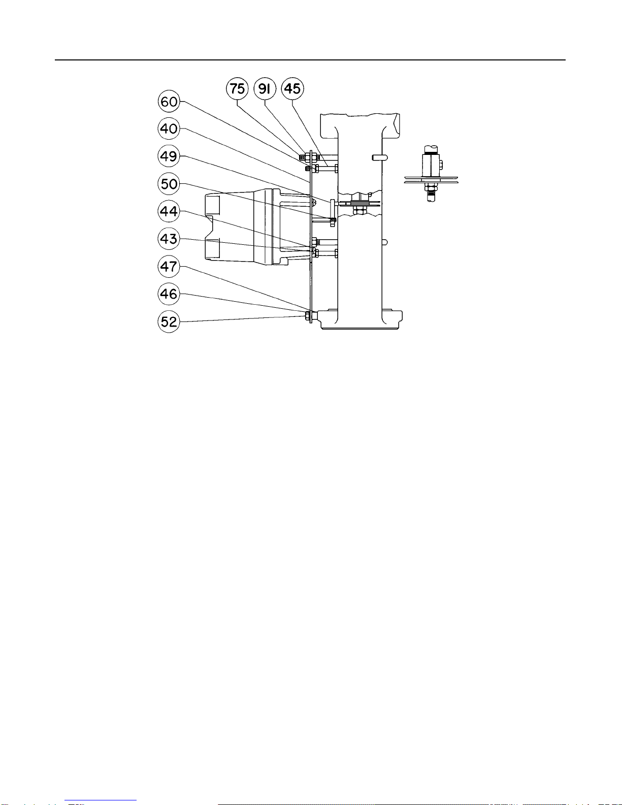
Type 350 and 350MO Actuators (figure 7)
40 Mounting plate, assembly, steel
Type 350 and 350MO
2-13/16 (71 mm) boss 10A8524X012
3-9/16 (90 mm) boss 12A2348X012
43 Machine screw, pl steel (4 req’d) 1C582428982
44 Lockwasher, pl steel (4 req’d) 1C225628982
45 Cap screw, pl steel (2 req’d)
Type 350
2-13/16 (71 mm) and 3-9/16 (90 mm) boss 1A352524052
Type 350MO
2-13/16 (71 mm) boss 1A352524052
3-9/16 (90 mm) boss 1C870224052
46 Lockwasher, pl steel 1C225728982
47 Spacer, pl steel
Type 350
2-13/16 in. (71 mm) boss 1N254324102
3-9/16 in (90 mm) boss (none req’d) - - -
Type 350MO
2-13/16 in. (71 mm) boss 1N254324102
3-9/16 (90 mm) boss 1N466124102
*Recommended spare parts

Type 304 & 304L
9
Figure6. Type 304L Switch Assembly
A
A
APPLY LUB/ADHESIVE
1
NOTES:
WIRE ASSEMBLIES REQUIRED ON SWITCHES WITH TERMINAL STRIP ONLY
RED WIRE ASSEMBLY (KEY 35) CONNECTS SWITCH NORMALLY CLOSED (NC) CONNECTION TO NC ON TERMINAL STRIP
BLUE WIRE ASSEMBLY (KEY 36) CONNECTS SWITCH COMMON (C) CONNECTION TO C ON TERMINAL STRIP
BLACK WIRE ASSEMBLY (KEY 37) CONNECTS SWITCH NORMALLY OPEN (NO) CONNECTION TO NO ON TERMINAL STRIP
30A8003–L/ IL
1
Key Description Part Number
49 Arm assembly, pl steel and stainless steel
Type 350 1U9987000A2
Type 350MO
2-13/16 in. (71 mm) boss 1U9987000A2
3-9/16 (90 mm) boss 1U4684X0012
50 Cap Screw, Hex Socket Head, steel 1H3697X0022
52 Cap screw, pl steel
Type 350
2-13/16 in. (71 mm) boss 1A352624052
3-9/16 in. (90 mm) boss 1C631224052
Type 350MO
2-13/16 in. (71 mm) boss 1A352624052
3-9/16 in. (90 mm) boss 1A553424052
60 Hex Nut, pl steel (2 req’d) 1A342124122
75 Hook bolt, steel (2 req’d)
Type 350MO, 3-9/16 in. (90 mm) boss 12A2454X012
All other types and boss sizes 10A8522X012
91 Hex nut, pl steel (4 req’d) 1A375324112
Type 352 and 352MO Actuators (figure 7)
40 Mounting plate assembly, steel
Type 352 and 352MO
2-13/16 in. (71 mm) boss 10A8524X012
Type 352
3-9/16 in. (90 mm) boss 12A6191X012
Type 352MO
3-9/16 in (90 mm) boss--3 in. max travel 11A6703X012
43 Machine screw, pl steel (4 req’d) 1C582428982
44 Lockwasher, pl steel (4 req’d) 1C225628982
45 Cap screw, pl steel (2 req’d) 1A352524052
46 Lockwasher, pl steel 1C225728982
Key Description Part Number
47 Plate spacer, pl steel
2-13/6 in. (71 mm) boss 1N254324102
3-9/16 in.(90 mm) boss (none req’d) - - -
49 Arm assembly, pl steel and stainless steel
2-13/16 in. (71 mm) boss 1U9987000A2
3-9/16 in. (90 mm) boss 1N8083000A2
50 Cap Screw, Hex Socket Head, steel 1H3697X0022
52 Cap screw, pl steel
2-13/16 in. (71 mm) boss 1A352624052
3-9/16 in. (90 mm) boss 1C631224052
60 Hex Nut, pl steel (2 req’d) 1A342124122
75 Hook bolt, steel (2 req’d)
Type 352MO, 3-9/16 in. (90 mm) boss 10A1934X012
All other types and boss sizes 10A8522X012
91 Hex nut, pl steel (4 req’d) 1A375324112
Type 353 and 353MO Actuators (figure 7)
40 Mounting plate ass’y, steel
Type 353 and 353MO
2-13/16 in. (71 mm) boss 13A7991X012
Type 353
3-9/16 in. (90 mm) boss 10A8528X012
Type 353MO
3-9/16 (90 mm) boss 12A2348X012
43 Machine screw, pl steel (4 req’d) 1C582428982
44 Lockwasher, pl steel (4 req’d) 1C225628982
45 Cap screw, pl steel (2 req’d)
Type 353 and 353MO
2-13/16 (71 mm) boss 1A352524052
Type 353
3-9/16 in. (90 mm) boss 1A352524052
Type 353MO
3/9/16 in. (90 mm) boss 1C870224052

Type 304 & 304L
10
Figure7. Typical Switch Mounting for 350 Series Actuators; T
ype 470 and 478 Actuators, Size 40 through 68; and T
ype 657 and 667
Actuators, Size 40 Through 70, 70MO, and 80MO
42A2088–D/ IL
NOTE:
REFER TO THE PARTS LIST FOR KEY NUMBERS DESCRIPTION AND ORDERING INFORMATION. REFER
TO THE ADDITION PARTS FOR FIELD MOUNTING SECTION FOR ACTUATOR PARTS REQUIRED FOR
MOUNTING THE TYPE 304 AND 304L SWITCHES.
Key Description Part Number
46 Lockwasher, pl steel 1C225728982
47 Plate spacer, pl steel
Type 353 and 353MO
2-13/16 (71 mm) boss 1N254324102
Type 353
3-9/16 in. (90 mm) boss (none req’d) - - -
Type 353MO
3-9/16 (90 mm) boss 1N466124102
49 Arm assembly, pl steel and stainless steel
Type 353 and 353MO
2-13/16 (71 mm) boss 1U9987000A2
Type 353
3-9/16 in. (90 mm) boss 1U9987000A2
Type 353MO
3-9/16 (90 mm) boss 1U4684X0012
50 Cap Screw, Hex Socket Head, steel 1H3697X0022
52 Cap screw, pl steel
Type 353 and 353MO
2-13/16 (71 mm) boss 1A352624052
Type 353
3-9/16 in. (90 mm) boss 1C631224052
Type 353MO
3-9/16 (90 mm) boss 1A553424052
60 Hex Nut, pl steel (2 req’d) 1A342124122
75 Hook bolt, pl steel, (2 req’d)
Type 353 and 353MO
2-13/16 (71 mm) boss 10A8522X012
Type 353
3-9/16 (90 mm) boss 10A8522X012
Key Description Part Number
75 Hook bolt, pl steel, (2 req’d)(cont’d)
Type 353MO
3-9/16 (90 mm) boss 12A2454X012
91 Hex nut, pl steel (4 req’d) 1A375324112
Type 470 Actuators (figures 7 and 8)
40A Mounting plate, steel
Size 30 2N4651X0012
Size 80 w/covered yoke 3N465425022
40 Mounting plate assembly, steel
Sizes 40, 43, and 46 10A8524X012
Sizes 60, 63, 64, and 68 10A8528X012
Size 86 11A6711X012
Sizes 80, 100, and 130 11A6709X012
41 Clip, stainless steel
Sizes 80, 80 w/covered yoke, 86, 100, and
130 only 1N254136012
43 Machine screw, pl steel (4 req’d) 1C582428982
44 Lockwasher, pl steel (4 req’d) 1C225628982
45 Cap screw, pl steel
Size 30 (2 req’d) 1C631224052
Size 40 thru 68 (2 req’d) 1A352524052
Size 86 (2 req’d) 1A914524052
Sizes 80, 100, and 130 (2 req’d) 1A782024052
Sizes 80 w/covered yoke (3 req’d) 1C631224052
46 Lockwasher, pl steel
Size 30 and size 80 w/covered
yoke (3 req’d) 1C225728982
All other sizes (1 req’d) 1C225728982

Type 304 & 304L
11
Figure8. Typical Switch Mounting for T
ype 470 Actuator
, Size 30 and T
ype 470 Actuator
, Size 80 with Covered Yoke
NOTE:
REFER TO THE PARTS LIST FOR KEY NUMBER DESCRIPTION AND ORDERING INFORMATION. REFER
TO THE ADDITIONAL PARTS FOR FIELD MOUNTING SECTION FOR ACTUATOR PARTS REQUIRED FOR
MOUNTING THE TYPE 304 AND 304L SWITCHES.
STEM CONNECTOR
FOR SIZE 80 AND
LARGER
OPTIONAL
STEM CONNECTION
30A7539–E/ IL
Key Description Part Number
47 Spacer, pl steel
Size 30 1N466224102
Sizes 40, 43, and 46 1N254324102
All other sizes (none req’d) - - -
49 Arm assembly, pl steel and stainless steel
Size 30 thru 68 1U9987000A2
Size 80 thru 130 11A6825X012
Size 80 with covered yoke 1N8083000A2
50 Cap Screw, Hex Socket Head, steel 1H3697X0022
51 Machine screw, pl steel (2 req’d)
Sizes 80, 86, 100, and 130 only 1E490528982
52 Cap screw, pl steel
Size 30 1B787724052
Sizes 40, 43, and 46 1A352624052
Size 60 thru 130 1C631224052
Size 80 w/covered yoke (none req’d) - - -
60 Hex Nut, pl steel (2 req’d)
Sizes 40, 43, 46, 60, 63, 64, and 68 only 1A342124122
75 Hook bolt, pl steel (2 req’d)
Size 30 and size 80 w/covered yoke (none req’d) - - -
Size 40 thru 68 10A8522X012
Size 86 11A6712X012
Sizes 80, 100, and 130 11A6710X012
91 Hex nut, pl steel
Size 30 and size 80 w/covered yoke (none req’d) - - -
Sizes 40, 43, 46, 60, 63, 64, and 68 (4 req’d) 1A375324112
Sizes 80, 86, 100, and 130 (6 req’d) 1A375324112
Type 478 Actuator (figure 7)
40 Mounting plate assembly, steel
Sizes 40, 43, and 46 10A8526X012
Sizes 60 and 64 10A8534X012
Size 68 11A6700X012
43 Machine screw, pl steel (4 req’d) 1C582428982
Key Description Part Number
44 Lockwasher, pl steel (4 req’d) 1C225628982
45 Cap screw, pl steel
Sizes 40, 43, 46, and 68 (2 req’d) 1B762424052
Sizes 60 and 64 (2 req’d) 1A352524052
46 Lockwasher, pl steel 1C225728982
47 Spacer, pl steel
Sizes 40, 43, and 46 1N465824102
Sizes 60 and 64 (none req’d) - - -
Size 68 1N254324102
49 Arm assembly, steel & stainless steel
Size 68 11A6717X012
All other sizes 1R5304000A2
50 Cap Screw, Hex Socket Head, steel 1H3697X0022
52 Cap screw, pl steel
Sizes 40, 43, and 46 1B787724052
Sizes 60 and 64 1C631224052
Size 68 1A352624052
60 Hex Nut, pl steel (2 req’d) 1A342124122
75 Hook bolt, steel (2 req’d) 10A8522X012
91 Hex nut, pl steel (4 req’d) 1A375324112
Type 478-16 Actuator (figures 9 and 14)
40 Mounting plate assembly, steel
Sizes 60 and 68 10A8532X012
Sizes 80 and 100 11A6714X012
43 Machine screw, pl steel (4 req’d) 1C582428982
44 Lockwasher, pl steel (4 req’d) 1C225628982
45 Cap screw, pl steel
Sizes 60 and 68 (3 req’d) 1A352524052
Sizes 80 and 100 (2 req’d) 1A344524052
46 Lockwasher, pl steel 1C225728982
49 Arm assembly, pl steel and stainless steel
Sizes 60 and 68 only 1V2586X0012
49A Follower Pin, stainless steel
Sizes 80 and 100 only 11A6715X012

Type 304 & 304L
12
Figure9. Typical Switch Mounting for T
ype 478-16 Actuator
,
Sizes 60 and 68
NOTE:
REFER TO THE PARTS LIST FOR KEY NUMBER DESCRIPTION AND
ORDERING INFORMATION. REFER TO THE ADDITIONAL PARTS FOR FIELD
MOUNTING SECTION FOR ACTUATOR PARTS REQUIRED FOR MOUNTING
THE TYPE 304 AND 304L SWITCHES.
42A2092–C/ IL
Key Description Part Number
49B Arm, pl steel
Sizes 80 and 100 only 16A1156X012
49C Hex nut, pl steel
Sizes 80 and 100 only 1A352224122
50 Cap Screw, Hex Socket Head, steel 1H3697X0022
52 Cap screw, Hex Socket Head, steel 1C631224052
60 Hex Nut, pl steel (3 req’d)
Sizes 60 and 68 1A342124122
75 Hook bolt, pl steel
Sizes 60 and 68 (3 req’d) 10A8522X012
Sizes 80 and 100 (2 req’d) 11A6710X012
91 Hex nut, pl steel (6 req’d) 1A375324112
Type 480-15 Actuator (not shown)
40A Mounting plate, steel 20A1484X012
41 Stem disc, stainless steel (2 req’d) 1P661238992
43 Machine screw, pl steel (4 req’d) 1H340328992
44 Lockwasher, pl steel (4 req’d) 1C225628982
45 Cap screw, pl steel (2 req’d) 1C631224052
46 Lockwasher, pl steel (2 req’d) 1C225728982
49 Arm assembly, stainless steel
Sizes 30-40 1R5305000A2
Size 60 1R5306X0012
50 Cap Screw, Hex Socket Head, steel 1H3697X0022
53 Disc spacer, steel 1R395735132
Type 480-16 Actuator (not shown)
40A Mounting plate, steel 30A0426X012
Figure 10. T
ypical Switch Mounting for T
ype 513 and 513R
Actuators
NOTE:
REFER TO THE PARTS LIST FOR KEY NUMBER DESCRIPTION AND
ORDERING INFORMATION. REFER TO THE ADDITIONAL PARTS FOR FIELD
MOUNTING SECTION FOR ACTUATOR PARTS REQUIRED FOR MOUNTING
THE TYPE 304 AND 304L SWITCHES.
32A2267–B/ IL
Key Description Part Number
41 Stem disc, stainless steel (2 req’d) 1R945836012
43 Machine screw, pl steel (4 req’d) 1C582428982
44 Lockwasher, pl steel (4 req’d) 1C225628982
45 Cap screw, pl steel (2 req’d) 1C631224052
49 Arm assembly, stainless steel 1V2586X0012
50 Cap Screw, Hex Socket Head, steel 1H3697X0022
53 Disc spacer, stainless steel 1R763935132
Type 513 and 513R Actuators (figure 10)
40A Mounting plate, steel 3N918125022
43 Machine screw, pl steel (4 req’d) 1A345928982
44 Lockwasher, pl steel (4 req’d) 1C225628982
45 Cap screw, pl steel (2 req’d)
Size 20 1A352624052
Size 32 1A352524052
46 Lockwasher, pl steel (2 req’d) 1C225728892
49 Arm assembly, steel & stainless steel 1U9987000A2
50 Cap Screw, Hex Socket Head, steel 1H3697X0022
54 Spacer, pl steel (2 req’d)
Size 32 only (not shown) 1F906724092
Type 585 and 585R Actuators (figure 11)
29 Cap Screw, pl steel (4 req’d) T13402T0012
40 Mounting plate, pl steel
Sizes 25 & 50 31B5273X012
Size 100 31B5647X012
43 Machine screw, pl steel (2 req’d) 14A9875X012
45 Cap screw, pl steel (4 req’d)
Sizes 25 & 50 1J3880X0012
Size 100 1A407824052

Type 304 & 304L
13
Figure
1
1. T
ypical Switch Mounting for T
ype 585 and 585R Actuators, Sizes 25, 50, and 100
TOP VIEW
TOP VIEW
STEM BRACKET VIEW
STEM BRACKET VIEW
SIZES 25 & 50
SIZE 100
NOTE:
REFER TO THE PARTS LIST FOR KEY NUMBER DESCRIPTION AND
ORDERING INFORMATION
HOLE 3
HOLE 4 HOLE 2
ACTUATOR
STEM
HOLE 1
HOLE 2
ACTUATOR
STEM
HOLE 1
40B0958–B
B2226 / IL
HOLE
NO. TRAVEL
Inches mm
1
2
3
4
1–1/8 or less
1–1/2 to 2
2–1/2 to 3
3–1/2 to 4
29.6 or less
38.1 to 50.4
63.5 to 229
88.9 to 102
37A9020–B
B1819–1/ IL

Type 304 & 304L
14
Figure
12. T
ypical Switch Mounting for T
ype 585C and 585CR Actuators
44B6341/ IL
Key Description Part Number
47 Spacer, pl steel (4 req’d)
Sizes 25 & 50 1N254324102
105 Sleeve, 416 stainless steel 18A0640X012
106 Operating arm, pl steel
Sizes 25 and 50 10B9997X012
Size 100 21B2692X012
Type 585C and 585CR Actuators (figure 12)
40 Mounting Plate, (steel) 24B6331X012
43 Cap Screw, zn pl steel (4 req’d) 1A391724052
44 Lockwasher, pl steel (4 req’d) 1C225628982
45 Cap Screw, pl steel (2 req’d) 1A352624052
46 Lockwasher pl steel (2 req’d) 1C225728982
65 Washer pl steel (2 req’d) 1B865928982
49 Arm Assembly 1U9987000A2
50 Cap Screw, S31600 SST 1H3697X0022
109 Stem Bracket, S30400 SST ENC HT
Size 25 24B6318X012
Size 50 24B6332X012
Type 657 Actuator (figures 7, 13, 14, and 15)
40A Mounting plate, steel
Sizes 30, 34, and 34MO 2N253528992
Size 34MO, 40MO, 45MO, 50MO, and 60MO
w/3582 or 3583
3U313025092
Sizes 40, 45, and 46 w/covered yoke 2N253628992
Sizes 40MO and 45MO 2N253628992
Sizes 50 and 60 w/covered yoke 2N253728992
Size 70 w/covered yoke 3N879925022
40 Mounting plate assembly, pl steel
Sizes 40, 45, and 46 10A8524X012
Sizes 50 and 60 10A8528X012
Size 70 12A6191X012
Size 70MO w/maximum 3 in. (76 mm) travel 11A6703X012
Size 70MO w/maximum 4 in. (102 mm) travel 15A7816X012
Sizes 80 and 80MO 11A6705X012
Size 87 11A6711X012
Size 100 15A6809X012
Figure 13. T
ypical Switch Mounting for T
ype 657 and 667
Actuators, Sizes 30, 34, and 34MO; and Size 40
through 70 with Covered Y
oke
NOTE:
REFER TO THE PARTS LIST FOR KEY NUMBER DESCRIPTION AND
ORDERING INFORMATION. REFER TO THE ADDITIONAL PARTS FOR FIELD
MOUNTING SECTION FOR ACTUATOR PARTS REQUIRED FOR MOUNTING
THE TYPE 304 AND 304L SWITCHES.
30A7540–F
Key Description Part Number
41 Clip, stainless steel
Sizes 80, 80MO, and 87 1N254136012
Size 100 15A6808X012

Type 304 & 304L
15
Figure
14. T
ypical Switch Mounting for T
ype 470 Actuator
,
Size 80 and 100; 478-16 Actuator
, Sizes 80 and 100;
and T
ype 657 and 667 Actuators, Sizes 80, 80MO,
and 87
NOTE:
REFER TO THE PARTS LIST FOR KEY NUMBER DESCRIPTION AND
ORDERING INFORMATION. REFER TO THE ADDITIONAL PARTS FOR FIELD
MOUNTING SECTION FOR ACTUATOR PARTS REQUIRED FOR MOUNTING
THE TYPE 304 AND 304L SWITCHES.
STEM CONNECTION FOR LESS THAN 8–1/8 INCHES (207 mm) TRAVEL
HOOK-UP FOR
8-1/8 INCHES
(207 mm) TRAVEL
STEM CONNECTOR
FOR SIZE 80 AND
LARGER
42A2156–D
A3202–2/ IL
1
1
Key Description Part Number
42 Plate spacer, steel (2 req’d)
Sizes 34MO and 40MO 1F906724092
Sizes 34MO and 40MO w/3582 or 3583 1V102624092
Size 45MO 1J830724092
Sizes 50MO and 60MO w/3582 or 3583 1J830724092
43 Machine screw, pl steel (4 req’d)
Size 30 1B822728992
Size 34, 34MO, 40MO,
and size 40 w/covered yoke 1H340328992
Sizes 34MO, 40MO, 45MO, 50MO, and 60MO
w/3582 or 3583
1A345928982
All other sizes 1C582428982
44 Lockwasher, pl steel (4 req’d) 1C225628982
45 Cap screw, pl steel
Sizes 30 and 34 and size 40 w/covered
yoke (3 req’d) 1C631224052
Sizes 34MO and 40MO (3 req’d) 1A352624052
Sizes 45, 46, and 70 w/covered yoke (2 req’d) 1C631224052
Sizes 34MO, 40MO, and 45MO
w/3582 or 3583 (2 req’d)
1D770424052
Sizes 40, 45, 46, 50, 60, and 70 (2 req’d) 1A352524052
Size 45MO (2 req’d) 1C379124052
Sizes 50 and 60 w/covered yoke (3 req’d) 1C631224052
Sizes 50MO and 60MO w/3582 or 3583 (2 req’d) 1F960324052
Size 70MO w/maximum 3 or 4 in (76 or 102
mm) travel (2 req’d) 1A352524052
Sizes 80 and 80MO (2 req’d) 1A344524052
Size 87 (2 req’d) 1A914524052
Size 100 (3 req’d) 1A344924052
Key Description Part Number
46 Lockwasher, pl steel
Sizes 30, 34, 34MO, 40MO, and 45MO (3 req’d) 1C225728982
Sizes 34MO, 40MO, 45MO, 50MO and 60MO
w/3582 or 3583 (2 req’d)
1C225728982
Sizes 40, 45, 46, 50, 60 and 70
w/covered yoke (3 req’d) 1C225728982
Size 70MO w/maximum 3 or 4 in. (76 or 102
mm) travel (1 req’d) 1C225728982
Size 100 (total of 4 req’d)
(3 req’d)
1A505628982
(1 req’d)
1C225728982
Sizes 40, 45, 46, 50, 60, 70, 80, 80MO,
and 87 (1 req’d)
1C225728982
47 Plate spacer, pl steel
Sizes 30 and 34 (none req’d) - - -
Sizes 34MO and 40MO 1F906724092
Sizes 40, 45, and 46 1N254324102
Size 45MO 1U9573X0012
Sizes 45, 46, and 70 w/covered yoke 1J915424102
Sizes 50, 60, and 70 and sizes 40, 50 and 60
w/covered yoke (none req’d) - - -
Size 70MO w/maximum 3 or 4 in (76 or 102
mm) travel (none req’d) - - -
49 Arm assembly, pl steel and stainless steel
Sizes 30, 34, 34MO and 40MO 1U9987000A2
Sizes 40, 45, 46, 50, and 60 1U9987000A2
Sizes 40, 45, 46, 50, and 60 w/covered yoke 1U9987000A2
Size 45MO 1V6323X0012
Size 70 and size 70 w/covered yoke 1N8083000A2
Size 70MO w/maximum 3 in. (76 mm) travel 1N8083000A2
Size 70MO w/maximum 4 in. (102 mm) travel 1R5304000A2
Size 80MO 13A0480X012
Sizes 80, 87, and 100 11A6825X012
50 Cap Screw, Hex Socket Head, steel 1H3697X0022
51 Machine screw, pl steel (2 req’d)
Sizes 34MO, 40MO, 45MO, 50MO, and 60MO
w/3582 or 3583
1V405828982
Sizes 80, 80MO, 87, and 100 1E490528982
52 Cap screw, pl steel
Sizes 30, 34, 34MO, and 40MO (none req’d) - - -
Sizes 40, 45, and 46 and sizes 45, 46, and
70 w/covered yoke 1A352624052
Sizes 40, 50, and 60 w/covered yoke (none req’d) - - -
Size 45MO 1C379124052
Sizes 50, 60, 70, 80, 80MO, and 87 1C631224052
Size 70MO w/maximum 3 or 4 in. (76 or 102
mm) maximum travel 1C631224052
Size 100 1A381624052
54 Mounting spacer, pl steel (4 req’d)
Size 30 1N254224102
Sizes 34, 34MO, and 40MO 1N254324102
Size 40 w/covered yoke 1N254324102
Sizes 45, 46, 50, and 60
w/covered yoke (none req’d) - - -
58 Arm, pl steel
Sizes 34MO, 40MO, 45MO, 50MO, and 60MO
w/ 3582 or 3583 1N807625142
59 Turnbuckle, pl steel
Sizes 34MO, 40MO, 45MO, 50MO, and 60MO
w/ 3582 or 3583 1R683999012
60 Hex Nut, pl steel (2 req’d) (not shown)
Sizes 40, 45, 46, 50, 60, 70, and 70MO 1A342124122
60 Hex nut, pl steel (2 req’d)
Sizes 34MO, 40MO, 45MO, 50MO, and 60MO
w/3582 or 3583
1A839628982

Type 304 & 304L
16
Figure
15. T
ypical Switch Mounting for All Sizes of T
ype 657 and 667 Actuators with
Handwheel (MO) and T
ype 3582 Positioner or T
ype 3583 T
ransmitter
NOTE:
REFER TO THE PARTS LIST FOR KEY NUMBER DESCRIPTION AND
ORDERING INFORMATION. REFER TO THE ADDITIONAL PARTS FOR FIELD
MOUNTING SECTION FOR ACTUATOR PARTS REQUIRED FOR MOUNTING
THE TYPE 304 AND 304L SWITCHES.
42A1841–C/ IL
Key Description Part Number
75 Hook bolt, steel
Sizes 40, 45, 46, 50, 60, and 70 (2 req’d) 10A8522X012
Size 70MO w/maximum 3 or 4 in. (76 or 102
mm) travel (2 req’d) 10A1934X012
Size 87 (2 req’d) 11A6712X012
Sizes 80 and 80MO (2 req’d) 11A6706X012
Size 100 (3 req’d) 15A6807X012
91 Hex nut, pl steel
Sizes 40, 45, 46, 50, 60, and 70 (4 req’d) 1A375324112
Size 70MO w/maximum 3 or 4 in. (76 or 102 mm)
travel (4 req’d) 1A375324112
Sizes 80, 87, and 80MO (6 req’d) 1A375324112
Size 100 (9 req’d) 1A375324112
94 Lockwasher, pl steel (2 req’d)
Sizes 34MO, 40MO, 45MO, 50MO, and 60MO
w/3582 or 3583
1A329128982
Type 667 Actuator (figures 7, 13, 14, and 15)
40A Mounting plate, steel
Sizes 30, 34, 34MO, 40MO, and 45MO 2N253528992
Sizes 34MO, 40MO, and 45MO w/3582 3U313025092
Size 40, 45, and 46 w/covered yoke 2N253628992
Sizes 50 and 60 w/covered yoke 2N253728992
Size 70 w/covered yoke 3N879925022
40 Mounting plate assembly, steel
Size 40 10A8524X012
Key Description Part Number
40 Mounting plate assembly, steel (cont)
Sizes 45 and 46 12A4277X012
Sizes 50 and 60 10A8528X012
Sizes 70 and 70MO w/maximum 3 in. (76 mm)
travel 11A6703X012
Sizes 70 and 70MO w/maximum 4 in. (102 mm)
travel 15A7816X012
Sizes 80 and 80MO 11A6705X012
Size 87 11A6711X012
Size 100 15A6809X012
41 Clip, pl steel
Sizes 80, 80MO, and 87 1N254136012
Size 100 15A6808X012
42 Spacer, pl steel (2 req’d)
Sizes 34MO and 40MO 1F906724092
Sizes 34MO and 40MO w/3582 1V102624092
Size 45MO 1J830724092
43 Machine screw, pl steel (4 req’d)
Size 30 1B822728992
Sizes 34, 34MO, and 40MO 1H340328992
Size 34MO, 40MO, and 45MO w/3582 1A345928982
Size 40 w/covered yoke 1N254328992
All other sizes 1C582428982
44 Lockwasher, pl steel (4 req’d) 1C225628982
45 Cap screw, pl steel
(2 req’d)
Sizes 34MO, 40MO, and 45MO w/3582 1D770424052

Type 304 & 304L
17
Key Description Part Number
45 Cap screw, pl steel (cont)
(2 req’d)
Sizes 40, 45, 46, 50, 60, 70, and 70MO 1A352524052
Sizes 45, 46, and 70 w/covered yoke 1C631224052
Size 45MO 1C379124052
Sizes 80 and 80MO 1A344524052
Size 87 1A914524052
(3 req’d)
Sizes 30 and 34 1C631224052
Sizes 34MO and 40MO 1A352624052
Sizes 40, 50, and 60 w/covered yoke 1C631224052
Size 100 1A344924052
46 Lockwasher, pl steel
Sizes 30, 34, 34MO, 40MO, and 45MO (3 req’d) 1C225728982
Sizes 34MO, 40MO, and 45MO
w/3582 (2 req’d)
1C225728982
Sizes 40, 45, 46, 50, 60 and 70
w/covered yoke (3 req’d) 1C225728982
Sizes 70 and 70MO w/maximum 3 or 4 in.
(76 or 102 mm) travel (1 req’d) 1C225728982
Size 100 (total of 4 req’d)
(3 req’d)
1A505628982
(1 req’d)
1C225728982
Size 40, 45, 46, 50, 60, 80,
80MO, and 87 (1 req’d) 1C225728982
47 Plate spacer, pl steel
Sizes 30, 34, 50, 60, 70, and 70MO (none req’d) - - -
Size 34MO and 40MO 1F906724092
Size 40, 45, and 46 1N254324102
Sizes 40, 50, and 60 w/covered yoke (none req’d) - - -
Sizes 45, 46, and 70 w/covered yoke 1J915424102
Size 45MO 1U9573X0012
49 Arm assembly, pl steel and stainless steel
Sizes 30, 34, 34MO, 40, 40MO,
45, 46, 50, and 60 1U9987000A2
Sizes 40, 45, 46, 50, and 60 w/covered yoke 1U9987000A2
Size 45MO 1V6323X0012
Size 70 w/covered yoke 1N8083000A2
Sizes 70 and 70MO w/maximum 3 in. (76 mm)
travel 1N8083000A2
Sizes 70 and 70MO w/maximum 4 in. (102 mm)
travel 1R5304000A2
Sizes 80, 87, and 100 11A6825X012
Size 80MO 13A0480X012
50 Cap Screw, Hex Socket Head, steel 1H3697X0022
51 Machine screw, pl steel (2 req’d)
Sizes 34MO, 40MO, and 45MO w/3582 1V405828982
Sizes 80, 80MO, 87, and 100 1E490528982
52 Cap screw, pl steel
Sizes 30 and 34 (none req’d) - - -
Sizes 40, 45, and 46 1A352624052
Sizes 40, 50, and 60 w/covered yoke (none req’d) - - -
Sizes 45, 46, and 70 w/covered yoke 1A352624052
Size 45MO 1C379124052
Size 50, 60, 70, 70MO, 80, 80MO, and 87 1C631224052
Size 100 1A381624052
54 Mounting spacer, pl steel (4 req’d)
Sizes 30 and 34 and size 40 w/covered yoke 1N254224102
Sizes 34MO and 40MO 1N254324102
Sizes 45, 46, 50, 60, and 70 w/covered
yoke (none req’d) - - -
58 Arm, pl steel
Sizes 34MO, 40MO, and 45MO w/3582 1N807625142
59 Turnbuckle
Size 34MO, 40MO, and 45MO w/3582 1R683999012
Key Description Part Number
60 Hex Nut, pl steel (2 req’d)
Sizes 40, 45, 46, 50, 60, and 70 1A342124122
Sizes 34MO, 40MO, and 45MO w/3582 1A839628982
75 Hook bolt, pl steel
Sizes 40, 45, 46, 50, 60, and 70 (2 req’d) 10A8522X012
Size 70MO (2 req’d) 10A1934X012
Sizes 80 and 80MO (2 req’d) 11A6706X012
Size 87 (2 req’d) 11A6712X012
Size 100 (3 req’d) 15A6807X012
91 Hex nut, pl steel
Sizes 40, 45, 46, 50, 60, and 70 (4 req’d) 1A375324112
Sizes 80, 80MO, and 87 (6 req’d) 1A375324112
Size 100 (9 req’d) 1A375324112
94 Lockwasher, pl steel (2 req’d)
Sizes 34MO, 40MO, and 45MO w/3582 1A329128982
Type 329, 1051, 1052, 1061 and 1069 Actuators
(figures 16 and 17)
40A Mounting plate, steel
Types 329 and 1069 38A8037X012
Type 1051
Sizes 30, 40, and 60 36A5913X012
Type 1052
Sizes 30, 40, 60, and 70 36A5913X012
Type 1061
Sizes 30, 40, 60, and 68 36A5913X012
Sizes 80 and 100 38A5864X012
44 Lockwasher, pl steel (4 req’d) 1C225628982
45 Cap screw, pl steel (4 req’d) 1A391724052
105 Coupler 26A5914X012
106 Coupler plate ass’y, pl steel
Types 329 and 1069 18A8039X012
Types 1051 and 1052
Sizes 30 and 40 16A5916X012
Type 1061, size 30 16A5916X012
Type 1051, size 60 16A5917X012
Type 1052, sizes 60 and 70 16A5917X012
Type 1061, sizes 40, 60, and 68 16A5917X012
Type 1061, sizes 80 and 100 18A5863X012
Type 1051 and 1052 Size 33 Actuator (figure 18)
29 Cap screw, pl steel (4 req’d) 1C5958X0022
40A Mounting bracket, steel 38A4476X012
50 Machine screw, pl steel (2 req’d) 1B877628992
44 Lock washer, pl steel (4 req’d) 1C225628982
45 Cap screw, pl steel (4 req’d) 1B290524052
105 Coupler 26A5914X012
106 Drive plate ass’y, pl steel 17A9148X012
Type 1052, Size 20 Actuators (figure 19)
40A Mounting plate, steel 39A2482X012
44 Lockwasher, pl steel (4 req’d) 1C225628982
45 Cap screw, pl steel (4 req’d) 1B290524052
52 Cap screw, pl steel (4 req’d) 1A353124052
105 Coupler 26A5914X012
106 Coupler plate ass’y, pl steel 17A9148X022
Type 1066 and 1066SR Actuators (figure 20)
40A Mounting bracket, steel
Types 1066 and 1066SR
Styles F and G mounting
Sizes 20 and 27 38A4476X012
Size 75 38A4477X012
Types 1066 and 1066SR
Style H mounting
Sizes 20 and 27 38A4522X012
Size 75 38A4521X012

Type 304 & 304L
18
Figure
16. T
ypical Switch Mounting for T
ype 1051, 1052, and 1061 Actuators, Sizes 30, 40, 60, 68, and 70
NOTE:
REFER TO THE PARTS LIST FOR KEY NUMBER DESCRIPTION AND
ORDERING INFORMATION. REFER TO THE ADDITIONAL PARTS FOR FIELD
MOUNTING SECTION FOR ACTUATOR PARTS REQUIRED FOR MOUNTING
THE TYPE 304 AND 304L SWITCHES.
52A9379–F/ IL
Figure
17. T
ypical Switch Mounting for T
ype 329,1061,
and 1069 Actuators, Size 80 and Larger
NOTE:
REFER TO THE PARTS LIST FOR KEY NUMBER DESCRIPTION AND
ORDERING INFORMATION. REFER TO THE ADDITIONAL PARTS FOR FIELD
MOUNTING SECTION FOR ACTUATOR PARTS REQUIRED FOR MOUNTING
THE TYPE 304 AND 304L SWITCHES.
35A8010–C/ IL
Key Description Part Number
44 Lockwasher, pl steel (4 req’d) 1C225628982
45 Cap screw, pl steel (4 req’d) 1B290524052
Key Description Part Number
105 Coupler 26A5914X012
106 Drive plate assembly, pl steel
Types 1066 and 1066SR
Styles F, G, and H mounting
Sizes 20 and 27 17A9148X012
Size 75 17A9147X012
Type 1076 Actuator (figure 21)
40A Mounting plate, steel
Size 1 34A1595X012
Size 2 34A1600X012
Size 3 55A5033X012
43 Machine screw, pl steel 1P474328982
44 Lockwasher, pl steel (4 req’d) 1C225628982
45 Cap screw, pl steel (4 req’d) 1A391724052
49B Arm, pl steel
Size 1 14A1596X012
Sizes 2 and 3 14A1598X012
50 Machine screw, pl steel (2 req’d) 12A9688X012
85 Cap screw, pl steel (3 req’d)
Size 3 1C870224052
91 Hex nut, pl steel
Sizes 1 and 2 1A342124122
97 Connecting link 1R683999012
98 Trip arm, steel
Size 3 25A5032X012
99 Post, pl steel
Sizes 1 and 2 14A1599X012
101 Cap screw, pl steel (2 req’d)
Size 3 1A407824052
108 Spacer, steel (3 req’d) (not shown)
Size 3 1K766824092
Type 1077 Actuators (figure 22)
40A Mounting Plate, steel
Sizes 0-KE and 2-KE 49A8008X012

Type 304 & 304L
19
Figure
18. T
ypical Switch Mounting for T
ype 1051
and 1052 Actuator Size 33
NOTE:
REFER TO THE PARTS LIST FOR KEY NUMBER DESCRIPTION AND
ORDERING INFORMATION. REFER TO THE ADDITIONAL PARTS FOR FIELD
MOUNTING SECTION FOR ACTUATOR PARTS REQUIRED FOR MOUNTING
THE TYPE 304 AND 304L SWITCHES.
30B1535–A/ IL
Key Description Part Number
40A Mounting Plate, steel (cont)
Size 6-KE 36A5913X012
Sizes 7-KE and 9-KE 30B0650X012
Size 10-KE:6 30B8491X012
44 Lock Washer, pl steel (4 req’d) 1C225628982
45 Cap Screw, pl steel (4 req’d) 1A391724052
105 Coupler 26A5914X012
106 Coupler Plate Ass’y, pl steel
Size 0-KE 19A8006X012
Size 2-KE 19A8003X012
Size 6-KE 19A8954X012
Size 7-KE 19A8004X012
Sizes 9-KE and 10-KE:6 19A8005X012
Type 1078 Actuators (figure 23)
40A Mounting Bracket, steel
Size A 38A4477X012
Size AA 31B5750X012
Size AAA 38A4476X012
44 Lock Washer, pl steel (4 req’d) 1C225628982
45 Cap Screw, pl steel (4 req’d) 1B290524052
Figure 19. T
ypical Switch Mounting for T
ype 1052
Actuator, Size 20
NOTE:
REFER TO THE PARTS LIST FOR KEY NUMBER DESCRIPTION AND
ORDERING INFORMATION. REFER TO THE ADDITIONAL PARTS FOR FIELD
MOUNTING SECTION FOR ACTUATOR PARTS REQUIRED FOR MOUNTING
THE TYPE 304 AND 304L SWITCHES.
39A2422–A
A3203–1/ IL
INDICATOR
SCALE
CAP SCREW
INDICATOR
Figure
20. T
ypical Switch Mounting for T
ype 1066
and 1066SR Actuators
NOTE:
REFER TO THE PARTS LIST FOR KEY NUMBER DESCRIPTION AND
ORDERING INFORMATION. REFER TO THE ADDITIONAL PARTS FOR FIELD
MOUNTING SECTION FOR ACTUATOR PARTS REQUIRED FOR MOUNTING
THE TYPE 304 AND 304L SWITCHES.
INDICATOR
SCALE
CAP
SCREW
INDICATOR
39A0627–A
A3206–1/ IL
Key Description Part Number
105 Coupler 26A5914X012
106 Drive Plate Ass’y
Size A & AA, stainless steel 11B6946X012
Size AAA, pl steel 17A9148X032

Type 304 & 304L
20
Figure
21. T
ypical Switch Mounting for T
ype 1076 Actuator
NOTE:
REFER TO THE PARTS LIST FOR KEY NUMBER DESCRIPTION AND
ORDERING INFORMATION. REFER TO THE ADDITIONAL PARTS FOR FIELD
MOUNTING SECTION FOR ACTUATOR PARTS REQUIRED FOR MOUNTING
THE TYPE 304 AND 304L SWITCHES.
35A8014–A/ IL
45A9390–A / IL
This manual suits for next models
1
Table of contents
Other Fisher Switch manuals