NOTES
ON
REPAIR
AND
ADJUSTMENT
The
!1C501
(Micon
P.C.Board)
of
the
FM-9060
uses
two
types
of
as
follows.
TMP47C870N-4674Z
410
090
5708
TMP47C870N-4675Z
410
108
5904
When
changing
the
IC501
from
TMP47C870N-4674Z
to
TMP47C870Z-4675Z,
change
the
R735
(TUNER
P.C.Board)
from
3.3k
to
1k.
Resistor
for
use
in
R735
TMP47C870N-4674Z
CARBON
3.3K
JA
1/6W
401
026
4308
TMP47C870N-4675Z
CARBON
1K
JA
1/6W
401
024
7004
The
FE
P.C.Board
of
the
FM-9060
uses
the
following
two
types
of.
Refer
to
the
P.C.Board
Parts
List
as
there
are
different
types
of
PCB
parts.
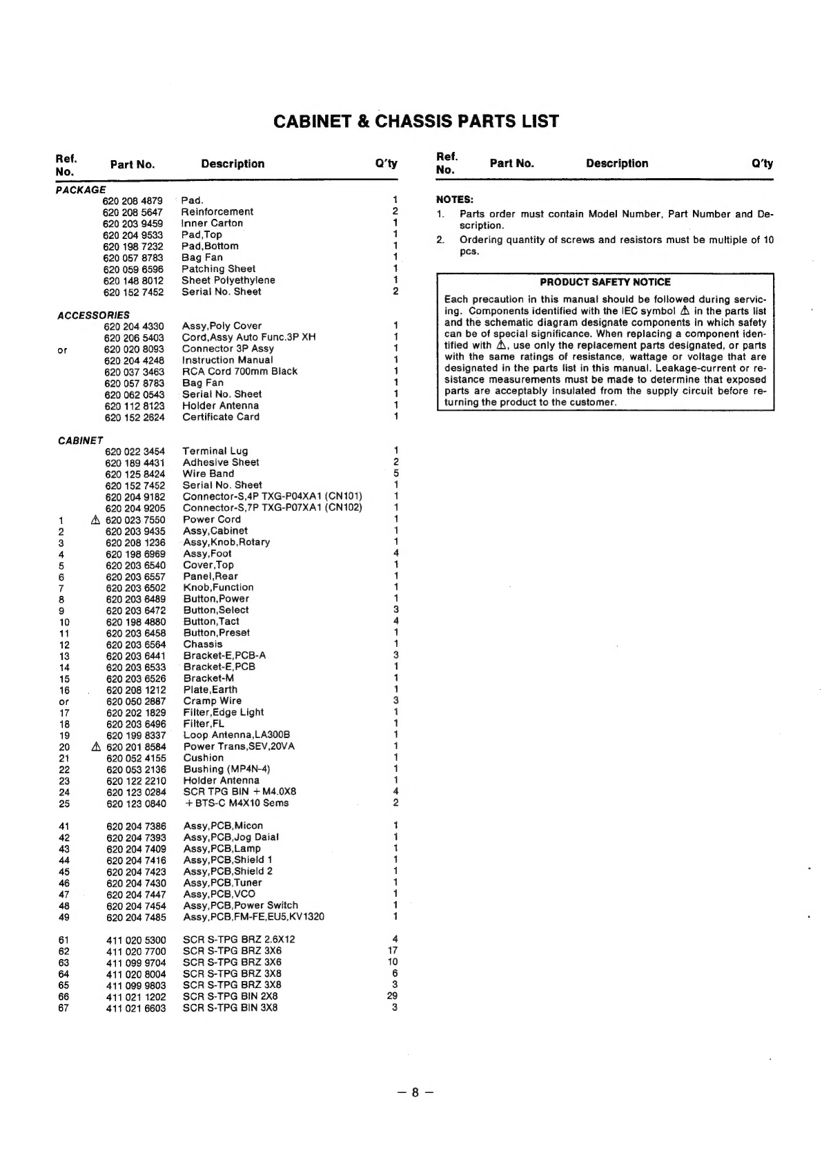
P.C.Board
Parts
List
shows
how
they
are
situated.
Te
620
204
7485
ASSY,PCB,FM-FE,EU5,KV1320
620
208
1335
ASSY,PCB,FM-FE,EU5,SVC211
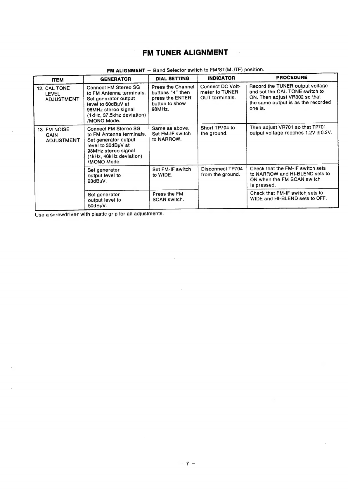
The
FM
CENTER
VOLTAGE
ALIGNMENT
differs
according
to
the
types
of
in
the
1C501.
Also,
the
FM
RF
FREQUENCY
COVER
ALIGNMENT
differs
according
to
the
type
of
FM-FE
P.C.Board.
Refer
to
FM
TUNER
ALIGNMENT.
REQUIRED
EQUIPMENT
FOR
TUNER
ADJUSTMENT
FM-SSG
:
MEGURO
MSG-290A
or
equivalent
products
more
than
90dB
S/N.
:
KIKUSUI
KSG-4300
or
equivalent
products
less
than
0.005%
THD.
AM-SSG
:
MEGURO
MSG-2554
or
equivalent
products.
STEREO-SSG
:
MEGURO
MSG-211G
or
equivalent
products
more
than
60dB
separation.
HARMONIC
DISTORTION
ANALYZER
:
HEWLETT
PACKARD
339A
or
equivalent
products.
2CH
AC
MILLIBAR
:
KIKUSUI
AVM25
or
equivalent
products.
CENTER
ZERO
METER
:
KIKUSUI
115A
or
equivalent
products.
HIGH
INPUT
RESISTER
DC
VOLTMETER
:
KIKUSUI
165A
or
equivalent
products.
FM-AM
IF
GENESCOPE
:
MEGURO
MSW-721D
or
equivalent
products.
FREQUENCY
COUNTER
:
TAKEDARIKEN
TR5822
or
equivalent
products.
OSCILLOSCOPE
:
2CH,
30MHz
DIGITAL
MULTI
METER
:
TAKEDARIKEN
TR-6843
or
equivalent
products.