Fisherbrand Accu500 User manual
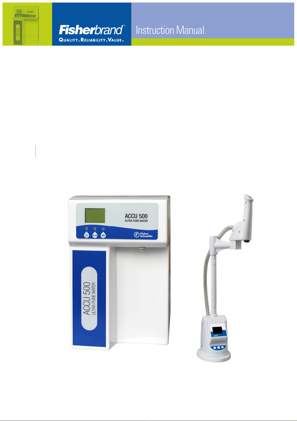
Accu500
Ultrapure and RO water system
USER MANUAL

www.eu.fishersci.com/fisherbrand
2
This Manual Is Applicable to the Following Accu500
Models
15409709 ACCU500 Water System, 10L/H with dispenser set
15419709 ACCU500 Water System, 15L/H with dispenser set
15429709 ACCU500 Water System, 20L/H with dispenser set
15439709 ACCU500 Water System, 30L/H with dispenser set

www.eu.fishersci.com/fisherbrand
3
Table of Contents
1 INTRODUCTION................................................................................................4
1.1 Product Features.............................................................................................5
1.2 Main Applications.............................................................................................6
1.3 Specifications ..................................................................................................7
1.4 Operation.........................................................................................................8
1.5 The Control Panel............................................................................................9
2 INSTALLATION................................................................................................11
2.1 Preparation for Installation.............................................................................11
2.2 Items Included...............................................................................................11
2.3 System Structure and Flow Diagrams ...........................................................12
2.4 Installation .....................................................................................................19
3 SYSTEM START UP AND OPERATION..........................................................30
3.1 Check List Prior to System Start Up..............................................................30
3.2 System Start Up and Time Setting.................................................................31
3.3 System Start Up ............................................................................................35
3.4 Routine Operation .........................................................................................40
4MAINTENANCE...............................................................................................42
4.1 Replacing the Prefilters..................................................................................43
4.2 Replacing AccuDuo H Pack and AccuDuo U Pack........................................44
4.3 Replacing Final Filter.....................................................................................44
4.4 Replacing the UV Lamp (For UV Models)......................................................45
4.5 Replacing the RO Membrane........................................................................47
4.6 Replacing the Fuse........................................................................................49
4.7 Cleaning the PE Tank....................................................................................50
5 BASIC TROUBLESHOOTING.........................................................................51
6 PARTS AND ORDER INFORMATION .............................................................53
Accu500 Systems................................................................................................53
Commonly Used Consumables...........................................................................54
Other Maintenance Spare Parts..........................................................................56
7 WARRANTY INFORMATION...........................................................................57
Conditions of Sales......................................................Erreur ! Signet non défini.
Water System Limited Warranty..................................Erreur ! Signet non défini.

www.eu.fishersci.com/fisherbrand
4
1 INTRODUCTION
This manual describes in detail about system working principle, performance
characteristics, installation, operation, and routine maintenance. Please read
this manual thoroughly for its instruction on installation, use and maintenance.
Proper installation, use and maintenance guarantee the continuous flow of high
quality ultrapure water.
Please contact us or your local distributor if you encounter any issues during
installation and use. Professional engineers are fully trained to support you.
Safety Information
WARNING!
To avoid electrical shock, always:
1) Use with a properly grounded electrical outlet of correct voltage and current
handling capacity.
2) Replace fuses with those of the same type and rating.
3) Disconnect from the power supply prior to maintenance and service.
4) Refer servicing to qualified personnel.

www.eu.fishersci.com/fisherbrand
5
1.1 Product Features
Accu500 lab water system provides an integrated solution for lab water using.
This series of systems produce Type I ultrapure water and Reverse Osmosis
(RO) water from tap water directly. Quality of ultrapure water produced meets or
exceeds ASTM, CLSI, CAP, and ISO Type I water standards.
The systems are compact designed to be easy to install, easy to operate and
easy to maintain.
This system has the following features:
•
It produces ultrapure water and RO water directly from tap water in one
single system.
•
System Incorporates advanced RO technology to provide pure & ultrapure
water at a low operation cost.
•
Electrical and water compartments are completely separated. Making the
unit safer to operate.
•
Multi-optional pre-filtration pack removes most large particles, calcium and
organic compounds to protect RO membrane to extend their usable life.
•
The unique automatic bypath sends water to the drain when RO water does
not meet preset quality standards.
•
System automatically rinses a new RO membrane. User does not need to
set special rinse program for a new RO membrane.
•
Fully automated system provides functions like RO membrane fouling
preventing flush, automatic recirculation of water every hour, and RO
membrane and cartridge life detection and warnings.
•
Two sets of dual-column polishing cartridges work sequentially to ensure
thorough removal of trace ions and organics in ultrapure water.
•
Ultrapure water dispenser is integrated with a high-precision resistivity
sensor (cell constant 0.01cm
-1
).
•
The color LCD on the dispenser displays water quality and other operation
parameters.

www.eu.fishersci.com/fisherbrand
6
•
Volumetric dispensing and calibration can be easily set up on the dispenser.
•
Various final filters (optional) can ensure bacteria free or pyrogen free water.
•
A dual wavelength UV lamp kills bacteria and reduces organics to trace
level.
•
Optional 30L or 60L PE tank with conical bottom ensures no dead space to
prevent bacteria growth.
•
Fisher Scientific provides full document support to meet user’s GMP, GLP,
FDA and other certification requirements.
1.2 Main Applications
Pure water can be used in many areas. Here are some typical applications.
With Ultrapure Water
With RO Water
Important and critical applications
Routine and non
-
critical
applications
•
HPLC (high performance liquid
chromatography) mobile phase
preparation
•
Preparation of reagent blank
solution
•
As sample diluents for GC, HPLC,
AA, ICP-MS and other analytical
techniques
•
Preparation of buffer and culture
media for mammalian cell culture
•
Preparation of molecular biology
reagents, etc.
•
Glassware cleaning
•
Washing machine for glassware
•
Water bath
•
Autoclave
•
Feed water for laboratory animals

www.eu.fishersci.com/fisherbrand
7
1.3 Specifications
Operating Voltage 110 V or 230 V
Power < 150 W
System Dimensions
Width × height x depth
12 × 19 × 20 in
30 × 48 × 51 cm
Dispenser Dimensions
Diameter × height
9 × 29 in
22 × 74 cm
Water Production Rate Ultrapure water (Type I): 1.5 L/min
RO water: typically 10/15/20/ 30 L/h (at 25℃)
Water Tank Capacity 30 L or 60 L
RO Rejection Rate > 95%
Resistivity of Ultrapure Water 18.2 MΩ.cm
TOC of Ultrapure Water < 5 ppb
Particles in Ultrapure Water
(>0.2 µm) <1 /mL
UV lamp 185/254 nm dual wavelength
Microorganism < 0,1 cfu/mL
Pyrogen Content < 0.001 EU/mL (with optional final
ultrafiltration filter)

www.eu.fishersci.com/fisherbrand
8
1.4 Operation
Accu500 integrated water systems produce ultrapure water and RO water
directly from tap water. Most particles, ions and organic compounds are
removed through the RO membrane before going to the storage tank. When in
need of ultrapure (UP) water, RO water flows through H Pack for further
de-ionization, through a UV ultraviolet light chamber (optional) to kill bacteria
and destroy trace organic pollutants in water, through a polish cartridge to
remove the last trace of ions, then a 0.2 µm final filter to the outlet.
After powering-up, the system goes into operation mode when the START
button is pressed. If RO water produced does not meet the preset quality
requirements, the RO indicator light on the panel will blink. RO water is
discharged to the drain until it meets quality standard, then into storage in the
water tank.
To dispense RO water, press the RO button on the system to dispense RO
water, and press RO button again to stop dispensing.
To dispense ultrapure water, press the dispense button on the dispenser to
dispense ultrapure water, and press the dispense button again to stop
dispensing.

www.eu.fishersci.com/fisherbrand
9
1.5 The Control Panel
The Main System:
•
MCU technology is used to measure water conductivity with automatic
temperature compensation to 25C.
•
Backlit LCD displays RO conductivity, temperature and system operation
status.
•
System is menu driven, and displays status of auto-run programs.
Remote Dispenser
•
A high precision resistivity sensor is used to measure resistivity of the
ultrapure water
•
Ultrapure water loop automatically recirculates every hour to prevent
bacterial growth
•
The color display on the dispenser shows operation parameters and quality
of ultrapure water
www.eu.fishersci.com/fisherbrand
10
Technical Specifications
Measurement Range Channel A (RO): 0 ~ 99.9 µS/cm;
UP: 0~18.2 MΩ·cm
Temperature Compensation
Range
Automatic temperature compensation of
readings
Temperature compensation range: 0 ~ 60℃to
25℃
Range of temperature
compensation coefficient
A channel: compensation coefficient setting
range:0 ~ 5% /℃
B channel: non-linear temperature
compensation
Displays:
The Main system
Dispenser Dot-matrix backlit LCD display
Color LCD
Conductivity (or resistivity)
alarm output
Can set output upper limit alarm for
conductivity (RO) and lower limit alarm for
resistivity(UP)
Communication Interface
Output
Standard RS-232C serial port. System can be
connected to devices with RS-232C interface to
export data or print records
Power Supply AC 230 V ± 10%, frequency (50 ± 0.5) Hz; or
AC 110 V ± 10%, frequency (60 ± 0.5) Hz
Maximum working
temperature for conductivity
meter 60℃
UV lamp 185/254 nm dual wavelength
www.eu.fishersci.com/fisherbrand
11
2 INSTALLATION
2.1 Preparation for Installation
2.1.1 Power Supply
Power supply must be properly grounded
2.1.2 Feed Water
Water type Municipal water
TDS < 1000 ppm
Water temperature 5 - 35℃
Water pressure 1.0 - 6.0 bar (15 - 90 psi)
2.1.3 Tools Needed (Not Included)
Scissors or a box opener to open packages and cut water tubing.
A wrench to install prefiltration kit.
2.2 Items Included
Accu500 main system included the following items:
1) One User Manual
2) Quality Certificate
3) Accessories Pack, including one power cord, one 1/4 inch and one 3/8 inch
PE tubing, water tank faucet, transparent tubing with a check valve, a 2-way
ball valve for the water tank, one roll of Teflon tape
Dispenser box contains the following items
a) Dispenser base
b) Swing arm extension
c) Dispenser head
d) Link bundle
www.eu.fishersci.com/fisherbrand
12
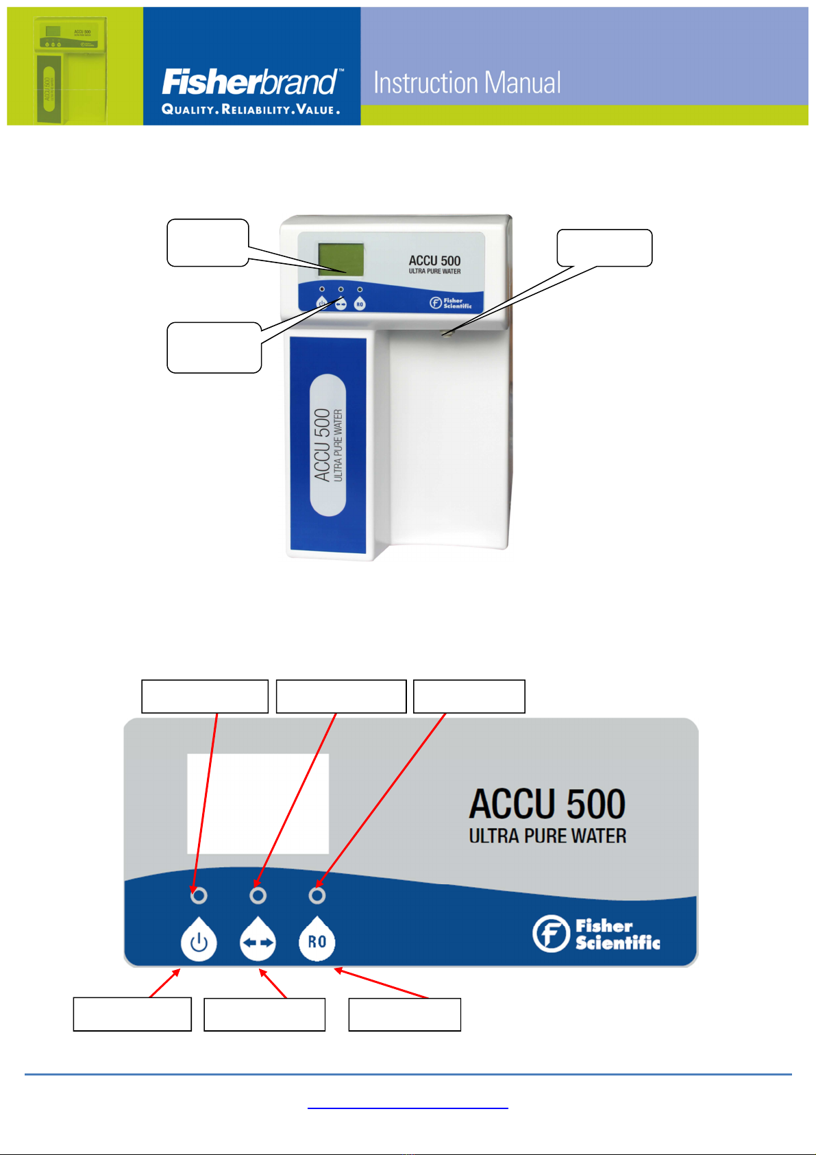
2.3 System Structure and Flow Diagrams
2.3.1 System Front View
2.3.2 System Control Panel
Display
Panel
Control
Panel
RO Outlet
Power Indicator
Setting Indicator
RO Indicator
Start/Standby
Cursor Button:
RO Dispense

www.eu.fishersci.com/fisherbrand
13
Main Buttons:
START:
Start system. Push once after system power up to start the system.
Push again to Standby.
RO
:
Controls RO water dispensing. Press once to dispense RO water,
press again to shut RO valve off.
Cursor:
To move cursor to set up system parameters.
Indicator Lights:
Power indicator:
Above START Button. Turns RED after power is
on.
RO indicator:
Above RO Button. It turns solid GREEN when
dispensing RO water.
RO indicator light is also used to indicate whether
RO water produced meets preset quality
parameters. If RO water produced does not meet
preset quality requirements, RO indicator light
BLINKS. RO water produced goes to drain. This
automatic operation is behind scene, thus does
not interfere with RO dispensing from the water
tank if there is water in the tank.
Setting indicator:
Above Cursor Button. The light BLINKS indicating
that parameters entered are valid.
www.eu.fishersci.com/fisherbrand
14
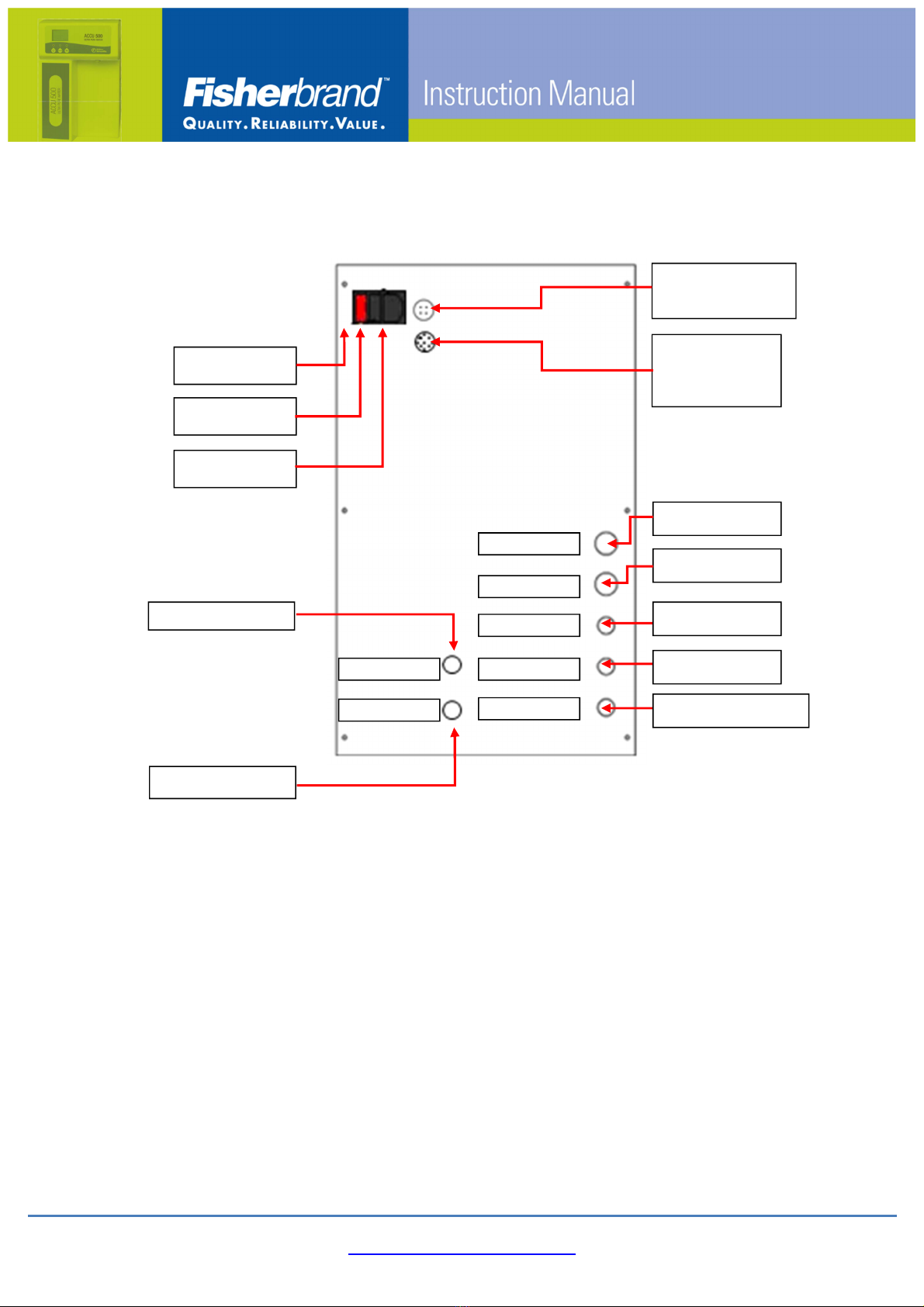
2.3.3 System Back Side View
In from Tap
In from Tank
Out to Tank
Spare RO Drain
Socket for Tank
Level Sensor
Socket for
Dispenser
data cable
Out to Dispenser
Out to System
RO Drain
FROMTANK
TOTANK
DRAIN
SPARE
TAP IN
TO POU
FROM POU
Socket
Power switch
Fuse

2.3.4 Accu500 Water Flow Diagram
Item Description NO.
A PrefiltrationSystem 1
B Low Pressure Switch 1
CRO Booster Pump,UP
Circulating Pump 2
E Solenoide Valve 8
F RO Membrane 2
G Check Valve 2
H Flow-Limiting Valve 3
IConductivity& Resistivity
Sensor 4
J Water Storage Tank 1
K Manual Valve 1
N UV lamp 3
0 H Pack, U Pack 1
P Tank Vent Filter 1
S Pressure regulator 1
U Liquid Level Sensor 1
Feed Loop
RO loop
EDI,UP Loop
F
Tap
C
F
RephiLe Bioscience, Ltd.
I2
C
3
G
J
P
E1
E2
E
3
E6
RO
Drain
K
H
I
5
N
N
A
E8
P
E5
E7
O
B
G
G
D
IN
OUT
TO POU
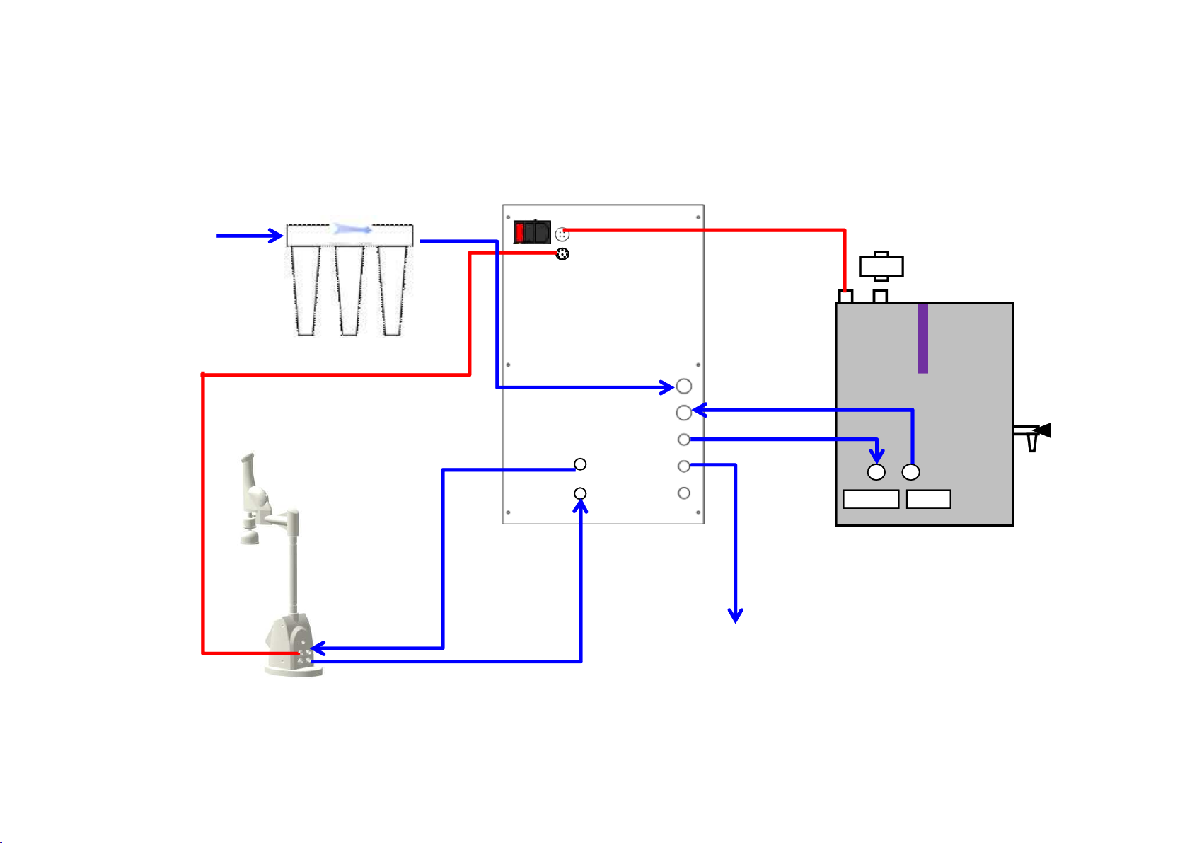
2.3.5 Accu500 External Connection Diagram
Prefiltration
Level Sensor
UVLamp
Ultrapure Water
1/4 inch tubing Drain Water
1/4 inch tubing
Pure Water
1/4 inch
tubing
Pure Water
3/8 inch tubing
Feed Water
3/8 inch tubing
TapWater
3/8 inch tubing
INLETOUTLET
Tank Vent Filter
Red Line: Electrical loop Blue Line: Water loop
www.eu.fishersci.com/fisherbrand
17
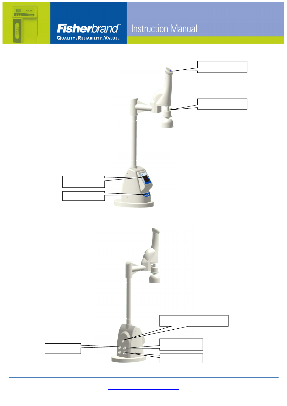
2.3.6 Water Dispenser
Dispenser button
UP outlet
Display panel
Control
Pad
Data port
Tubing to dispenser head
Out to system
In from system
www.eu.fishersci.com/fisherbrand
18
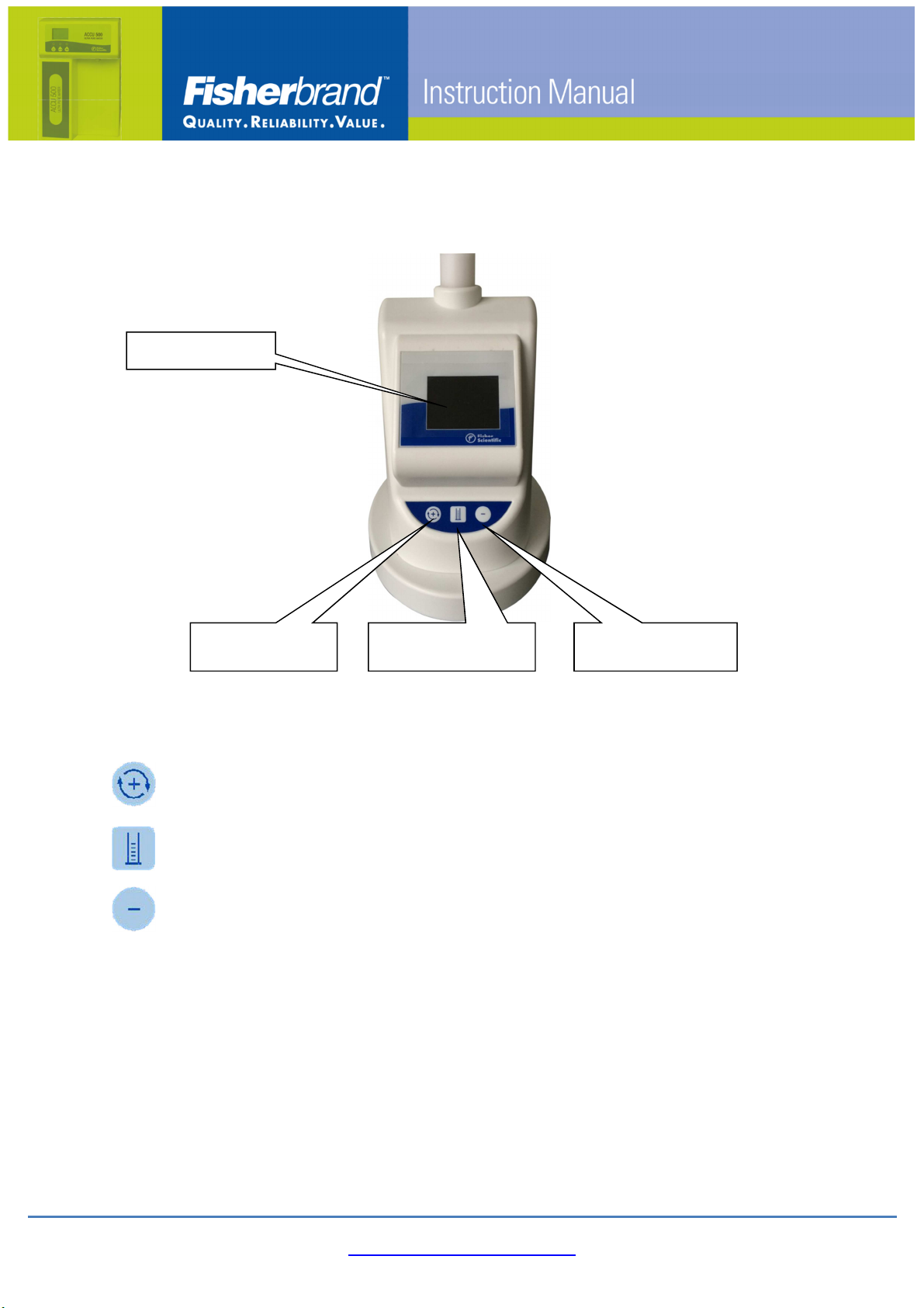
2.3.7 Water Dispenser control panel
1 In Ready mode, press 1 to start water recirculation. Press 1 and
2 simultaneously to enter user menu.
2 In Ready mode, press 2 to start volumetric dispensing setting.
Press 1 and 2 simultaneously to enter user menu.
3 In Ready mode, press 3 to release pressure in the system.
1
Recirculation
Button
2
Volumetric
Dispensing Button
3
Pressure Relief
Button
LCD Display
www.eu.fishersci.com/fisherbrand
19
2.4 Installation
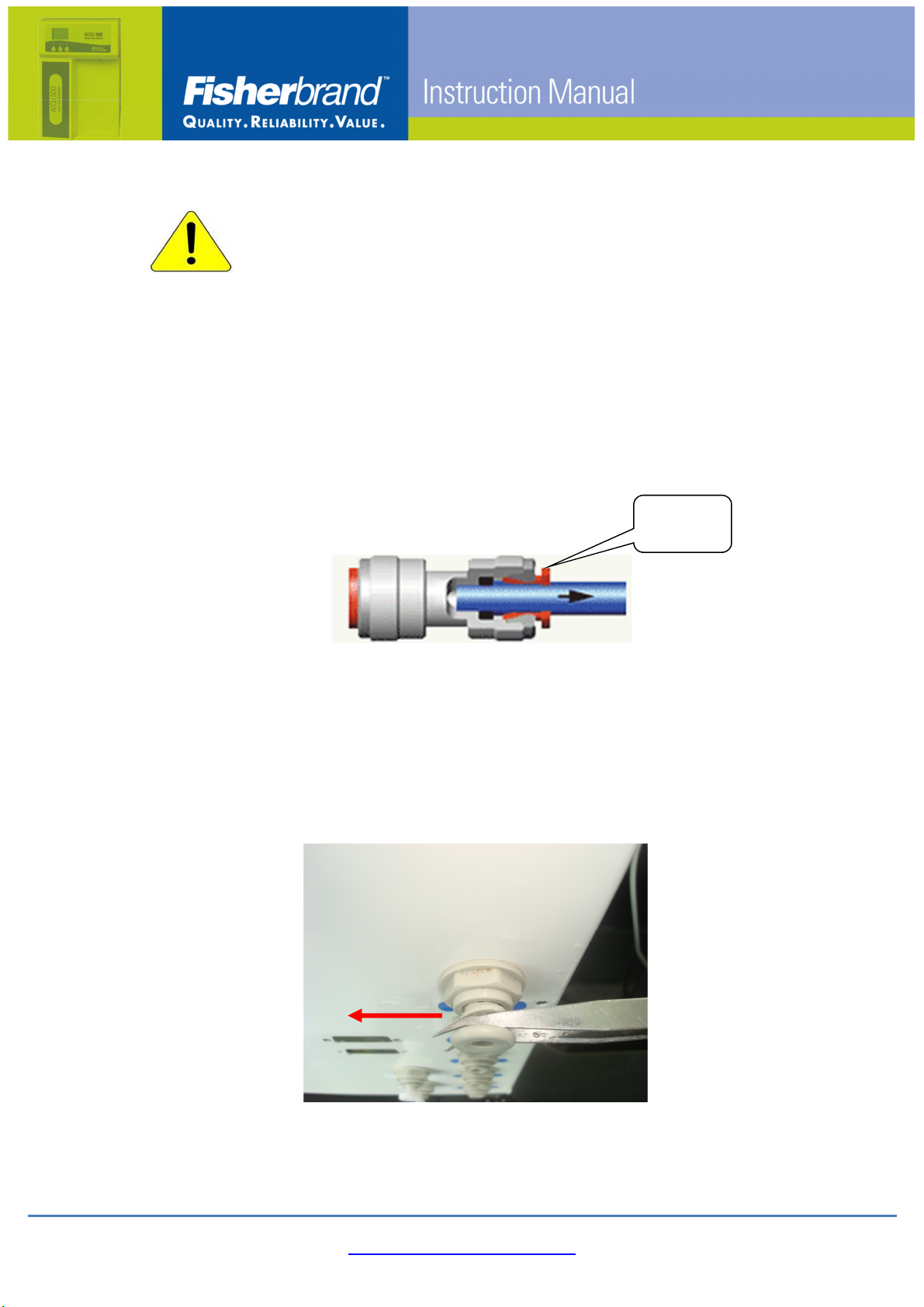
Attention
The connectors of the system are protected by stoppers. DO NOT attempt
to pull the stoppers out from the ports without unlocking the connector
first or use excessive force to pull the stoppers out as this will damage
the connector, rendering it useless.
Please follow the instruction below to remove the stoppers
A. Insert the tweezer to the gap between the stopper and the collet.
B. Pinch the tweezer and push it as the picture indicated to remove the
stoppers.
Collet
(push in)
www.eu.fishersci.com/fisherbrand
20
2.4.1 Installing the Remote Dispenser
a) Each end of cable and port are labeled. Connect tubing and cable to the
designated terminal.
b) Remove the remote dispenser from package and assemble it on a stable
bench.
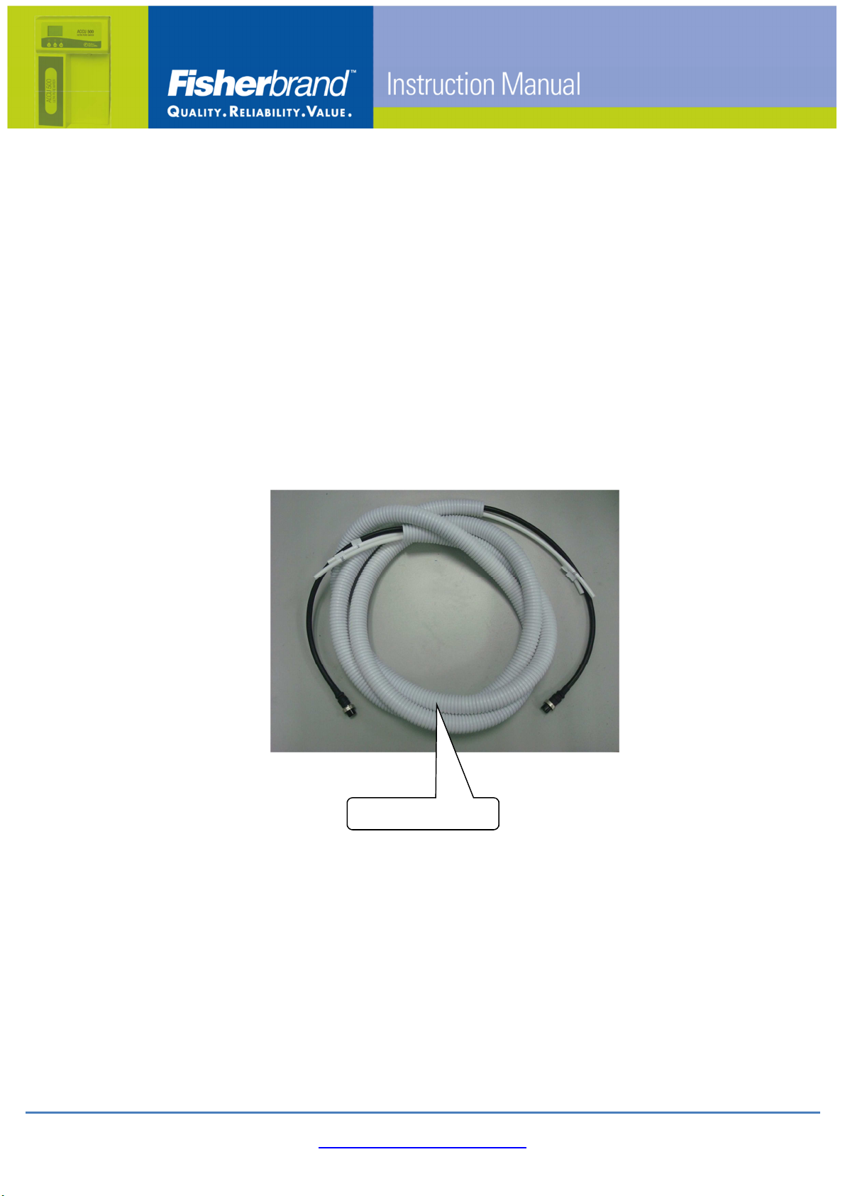
c) Take out the cable/tubing bundle from the package
d) Connect the 1/4 tubing in the bundle to the dispenser, and the other end to
the back of the RO water system.
e) Connect the 9 Pin data cable to the back of the remote dispenser and the
Accu500 RO system, then tighten the nuts.
T
he link bundle
Other manuals for Accu500
1
This manual suits for next models
4
Table of contents
Other Fisherbrand Laboratory Equipment manuals


