Fisherbrand Accu500 User manual
www.eu.fishersci.com/fisherbrand
Accu500
Ultrapure and RO water system
USER MANUAL

www.eu.fishersci.com/fisherbrand
2
This Manual Is Applicable to the Following Accu500
Models
15409699 ACCU500 Water System, 10L/H set
15429699 ACCU500 Water System, 15L/H set
15449699 ACCU500 Water System, 20L/H set
15469699 ACCU500 Water System, 30L/H set
15419699 ACCU500 Water System, 10L/H UV set
15439699 ACCU500 Water System, 15L/H UV set
15459699 ACCU500 Water System, 20L/H UV set
15479699 ACCU500 Water System, 30L/H UV set
15489699 ACCU500 Water System, 10L/H and 2-Pass RO set
15499699 ACCU500 Water System, 10L/H UV and 2-Pass RO set

www.eu.fishersci.com/fisherbrand
3
Table of Contents
1 INTRODUCTION...............................................................................................4
1.1
Product Features.........................................................................................5
1.2 Main Applications........................................................................................6
1.3 Specifications..............................................................................................7
1.4 Operation.....................................................................................................8
1.5 The Control Panel .......................................................................................9
2 INSTALLATION .............................................................................................. 10
2.1 Preparation for Installation.........................................................................10
2.2 Items Included...........................................................................................10
2.3 System Structure and Flow Diagrams.......................................................11
2.4
Installation .................................................................................................15
3 SYSTEM START UP AND OPERATION........................................................ 25
3.1 Check List Prior to System Start Up..........................................................25
3.2 System Start Up and Time Setting............................................................26
3.3 Routine Operation .....................................................................................32
4 MAINTENANCE.............................................................................................. 33
4.1 Replacing the Prefilters .............................................................................33
4.2 Replacing the AccuDuo H Pack, U Pack Cartridges and the
Final Filter........................................................................................................35
4.3 Replacing the UV Lamp (For UV Models) .................................................37
4.4 Replacing the RO Membrane....................................................................39
4.5 Replacing the Fuse ...................................................................................41
4.6 Cleaning the PE Tank................................................................................42
5 BASIC TROUBLESHOOTING........................................................................ 43
6 PARTS AND ORDER INFORMATION............................................................ 45
7 WARRANTY INFORMATION ......................................................................... 49

www.eu.fishersci.com/fisherbrand
4
1 INTRODUCTION
This manual describes in detail about system performance characteristics,
installation, operation, and routine maintenance. Please read this manual
thoroughly for its instruction on installation, use and maintenance. Proper
installation and maintenance guarantee the continuous flow of high quality
pure water.
Please contact us or your local distributor if you encounter any issues during
installation and use. Professional engineers are fully trained to support you.
Safety Information
WARNING!
To avoid electrical shock, always:
1) Use with a properly grounded electrical outlet of correct voltage and
current handling capacity.
2) Replace fuses with those of the same type and rating.
3) Disconnect from the power supply prior to maintenance and service.
4) Refer servicing to qualified personnel.

www.eu.fishersci.com/fisherbrand
5
1.1 Product Features
Accu500 lab water system is an integrated system which can produce
ultrapure and reverse osmosis (RO) water from tap water directly. Quality of
ultrapure water produced meets or exceeds ASTM, CLSI, CAP, and ISO
Type I water standards.
This system has the following features:
•
Electrical and water compartments are completely separated. Making
the unit safer to operate.
•
Pre-filtration pack removes most large particles, calcium and organic
compounds to protect RO membrane to extend their usable life.
•
System removes over 99% of large molecules and particles and 95% of
ions in water.
•
Fully automated control system has pre-rinse, RO membrane fouling
preventing flush, RO membrane and cartridge life detection and many
other functions.
•
System automatically rinses a new RO membrane. User does not need
to set special rinse program for a new RO membrane.
•
Two sets of dual-column purification cartridges work sequentially to
ensure thorough removal of trace ions and organics in water.
•
Resistivity is measured by a high-precision resistivity meter (conductivity
cell constant 0.01cm
-1
).
•
User can set water dispensing time for the ease of water collection.
•
A 0.2 µm final filter or an ultrafiltration filter (optional) removes bacteria
and final contaminants.
•
A dual wavelength UV lamp (optional) kills bacteria and reduces
organics to trace level.
•
The PE tank with conical bottom ensures no dead space to prevent
bacteria growth.
•
Tank Sanitization Modules (optional) can effectively inhibit microbial
growth by UV light.

www.eu.fishersci.com/fisherbrand
6
•
Tank vent filter has CO
2
scavenger to remove airborne contaminants,
including carbon dioxide and keep stored water at best quality possible
•
Built-in printer (optional) can be set to print various quality parameters.
•
Fisher Scientific provides full document support to meet user’s GMP,
GLP, FDA and other certification requirements.
1.2 Main Applications
Pure water can be used in many areas. Here are some typical applications.
With Ultrapure Water
With RO Water
Important and critical applications
Routine and non
-
critical
applications
•
HPLC (high performance liquid
chromatography) mobile phase
preparation
•
Preparation of reagent blank
solution
•
As sample diluents for GC, HPLC,
AA, ICP-MS and other analytical
techniques
•
Preparation of buffer and culture
media for mammalian cell culture
•
Preparation of molecular biology
reagents, etc.
•
Glassware cleaning
•
Washing machine for glassware
•
Water bath
•
Autoclave
•
Feed water for laboratory animals

www.eu.fishersci.com/fisherbrand
7
1.3 Specifications
Operating Voltage 110 V or 230 V
Power < 150 W
System Dimensions
Width × height x depth
12 × 19 × 20 in
30 × 48 × 51 cm
Tank Dimensions
Diameter × height
16 × 26 in
39 × 65 m
Water Production Rate Ultrapure water (Type I): 1.5 L/min
RO water: typically 10 to 50 L/h (at 25℃)
Water Tank Capacity 30 L or 60 L (optional)
RO Rejection Rate > 95%
Resistivity of Ultrapure Water 18.2 MΩ.cm
TOC of Ultrapure Water < 10 ppb, or < 5 ppb (with a dual wavelength
UV lamp)
Particles in Ultrapure Water
(>0.2 µm)
<1 /mL
UV lamp (optional) 185/254 nm dual wavelength
Microorganism < 0.1 cfu/mL
Pyrogen Content < 0.001 EU/mL (with a final ultrafiltration filter)

www.eu.fishersci.com/fisherbrand
8
1.4 Operation
Accu500 integrated water systems produce ultrapure water directly from tap
water. Most particles, ions and organic compounds are removed through the
RO membrane. Water is stored in the water tank. When in need of ultrapure
(UP) water, RO water flows through H Pack for further de-ionization, through
a UV ultraviolet light chamber (optional) to kill bacteria and destroy trace
organic pollutants in water, through a polish cartridge to remove the last
trace of ions, then a 0.2 µm final filter to the outlet.
After powering-up, system goes into operation mode when the START
button is pressed. If RO water produced does not meet the preset quality
requirements, the RO indicator light on the panel will blink. RO water is
discharged to the drain until it meets quality standard, then into storage in
the water tank. When the RO button is pressed, RO water from the water
tank flows to the RO outlet. RO water flow stops when the RO button is
pressed again. If the UP button is pressed, water from the water tank flows
through the H Pack cartridge, UV lamp chamber (optional), the U Pack
polishing cartridge to the UP outlet, then through a final filter to be
dispensed.

www.eu.fishersci.com/fisherbrand
9
1.5 The Control Panel
Main features of the control panel are:
•
MCU technology is used to measure water conductivity with automatic
temperature compensation to 25℃.
•
Backlit 12864 LCD displays RO conductivity, UP resistivity, temperature
and system operation status.
•
System is menu driven, and displays status of auto-run programs.
Technical Specifications
Measurement Range Channel A (RO): 0 ~ 99.9 µS/cm;
Channel B (UP): 0 ~ 18.2 MΩ·cm
Temperature Compensation
Range Automatic temperature compensation of
readings
Temperature compensation range: 0 ~ 60℃to
25℃
Range of temperature
compensation coefficient A channel: compensation coefficient setting
range:0 ~ 5% /℃
B channel: non-linear temperature
compensation
Display Dot-matrix backlit LCD display
Conductivity (or resistivity)
alarm output Can set output upper limit alarm for
conductivity (RO) and lower limit alarm for
resistivity (UP)
Communication Interface
Output Standard RS-232C serial port. System can be
connected to devices with RS-232C interface to
export data or print records
Power Supply AC 230 V ± 10%, frequency (50 ± 0.5) Hz; or
AC 110 V ± 10%, frequency (60 ± 0.5) Hz
Maximum working
temperature for conductivity
meter
60℃
Build-in Printer (optional) Print on demand for water parameters
UV lamp 185/254 nm dual wavelength (optional)
www.eu.fishersci.com/fisherbrand
10
2 INSTALLATION
2.1 Preparation for Installation
2.1.1 Power Supply
Power supply must be properly grounded
2.1.2 Feed Water
Water type Municipal water
TDS < 1000 ppm
Water temperature 5 - 35℃
Water pressure 1.0 - 6.0 bar (15 - 90 psi)
2.1.3 Tools Needed (Not Included)
Scissors or a box opener to open packages and cut water tubing.
A wrench to install prefiltration kit.
2.2 Items Included
Accu500 main system included the following items:
1) One User Manual
2) Quality Certificate
3) Accessories Pack, including one power cord, one 1/4 inch and one 3/8
inch PE tubing, water tank faucet, transparent tubing with a check valve,
a 2-way ball valve for the water tank, one roll of Teflon tape

www.eu.fishersci.com/fisherbrand
11
2.3 System Structure and Flow Diagrams
2.3.1 System Front View
2.3.2 System Control Panel
Display
Panel
Control Panel
(see explanation on
following page)
RO Outlet
UP Outlet
Power Indicator
RO Indicator UP Indicator
START Button:
Start/Standby
RO Button:
RO Dispense
UP Button:
UP Dispense

www.eu.fishersci.com/fisherbrand
12
Main Buttons:
START: Start system. Push once after system power up to start the
system. Push again to Standby.
RO: Controls RO water dispensing. Press once to dispense RO
water, press again to shut RO valve off.
UP: Controls ultrapure (UP) water dispensing. Press once to
dispense UP water, press again to stop dispensing.
Indicator Lights:
Power indicator: Above START Button. Turns RED after power is
turned on.
RO indicator: Above RO Button. It turns solid GREEN when dispensing
RO water.
RO indicator light is also used to indicate whether RO water produced
meets preset quality parameters. If RO water produced does not meet
preset quality requirements, RO indicator light BLINKS. RO water
produced goes to drain. This automatic operation is behind scene, thus
does not interfere with RO dispensing from the water tank if there is
water in the tank.
UP indicator: Above UP Button. It turns solid GREEN when
dispensing ultrapure water. If UP water does not meet quality
standards, this light BLINKS.

www.eu.fishersci.com/fisherbrand
13
2.3.3 System Back Side View
TAP IN
FROM TANK
TO TANK
DRAIN
SPARE
Socket Fuse Power switch
Spare for
2
-
Pass
In from Tap
In from Tank
Out to Tank
RO Drain
Socket for the
Tank Level Sensor
Socket for the
power cord to the
water tank
www.eu.fishersci.com/fisherbrand
14
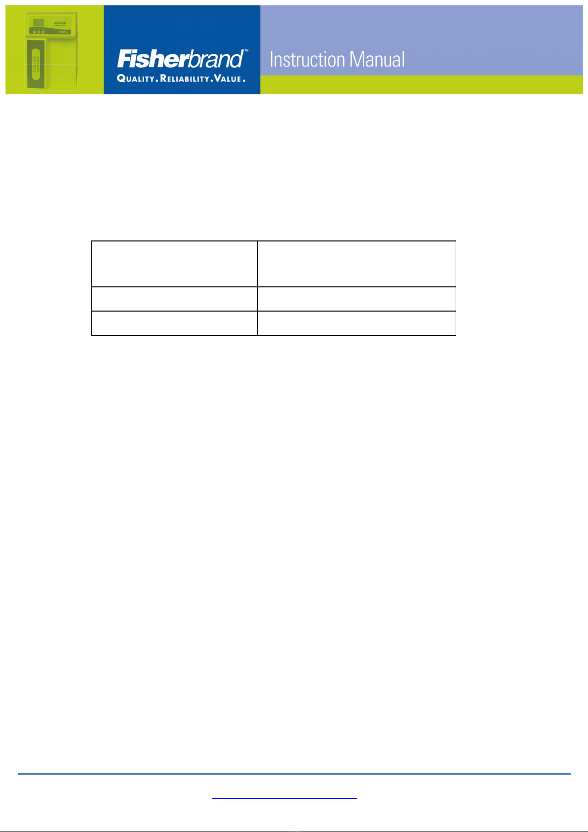
2.3.4 Accu500 Water Flow Diagram
2.3.5 Accu500 External Connection Diagram
Tank Level
Sensor
Tank Vent
Filter
9.53mm(3/8in)
tubing
6.35mm tubing
UV Lam
9.53mm(3/8in)
tubing
Drain 6.35mm(1/4in)
tubing
Prefiltration Pack
Ta
Water
ITEM COMPONENTS
A Water inlet
B Low pressure switch
C RO & UP pump
D Pressure gauge
E Solenoid valve
F RO housing
G Check valve
H Flow restrictor
I1 Conductivity sensor
I2 Resistivity sensor
J Pure water tank
K Manual Valve
M H & U pack
N UV lamp
P Tank vent filter
Q Final filter
U Tank level sensor
RO water loop
UP water loop
Feed water loop
C1
Pretreatm
ent
G
1/4"
1/4"
F
Tap
F
RephiLe Bioscience, Ltd.
B
LP
I1
C3
I2
A
J
P
E
E
E
E
K1
RO
Drain
K
U
H
D1
M2
M
N
Q
E
E
3/8"
3/8"
3/8"

www.eu.fishersci.com/fisherbrand
15
2.4 Installation
Attention
The connectors of the system are protected by stoppers. DO NOT
attempt to pull the stoppers out from the ports without unlocking the
connector first or use excessive force to pull the stoppers out as this
will damage the connector, rendering it useless.
Please follow the instruction below to remove the stoppers
A. Insert the tweezer to the gap between the stopper and the collet.
B. Pinch the tweezer and push it as the picture indicated to remove the
stoppers.
Collet
(push in)
www.eu.fishersci.com/fisherbrand
16
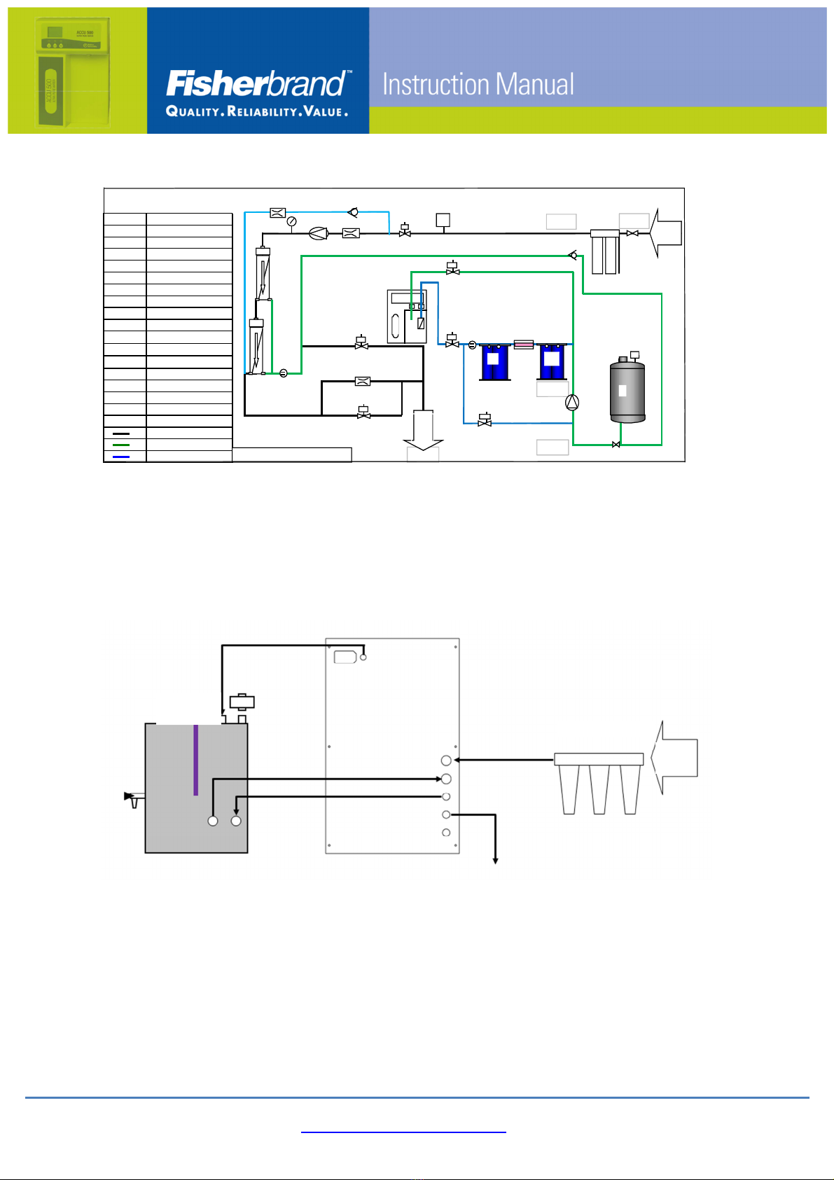
2.4.1 Installing the Prefiltration Module
Fisher Scientific provides two solutions for prefiltration, conventional three
stage kit and prefiltration stand (cartridge based)
Conventional three stage kit installation
Attention!
The Prefiltration pack is directional as indicated by the ARROW ( ).
Tap water must connect to the right side of the pack and exit to system
from the left side. NEVER reverse the order or the pack won't work.
1) Install the 3-way ball valve to the tap water inlet.
Note: Fitting is based on 1/2 inch diameter tubing. If the tap water outlet
is not 1/2 inch, you need an adaptor to convert it to 1/2 inch.
2) Install the filters: a typical set-up is 10µm PP filter-AC -1µm PP filter.
First, install the 10 µm filter into the upstream housing, the activated
carbon (AC) cartridge in the middle housing, and the 1 µm filter into the
downstream housing. Tighten the housing onto the Pack with the
AC
cartridge
3/8 inch Tubing
Inlet from
Tap
10 µm filter
1µm filter
Outlet to the
Water System
3-Way Ball
Valve
Special
Wrench
Teflon Tape and
other accessories
Pressure
Release
button

www.eu.fishersci.com/fisherbrand
17
special wrench.
3) Cut the included 3/8 inch tubing into two appropriate length tubing for
water inlet and outlet connections.
4) Connect one PE tubing from 3-way ball valve on the tap water outlet to
the water inlet on the Pack (Refer to Illustration above). Connect the
other PE tubing to the water outlet of the Prefiltration pack.
5) Put the outlet tubing into a sink. Turn on tap water and let it run for a
few minutes to clean up impurities which might exist in the pack.
6) Block the water outlet with your finger during the process to check
whether the assembly leaks.
7) Turn off the tap water. Connect the outlet PE tubing to the inlet of the
water system to complete the installation.

www.eu.fishersci.com/fisherbrand
18
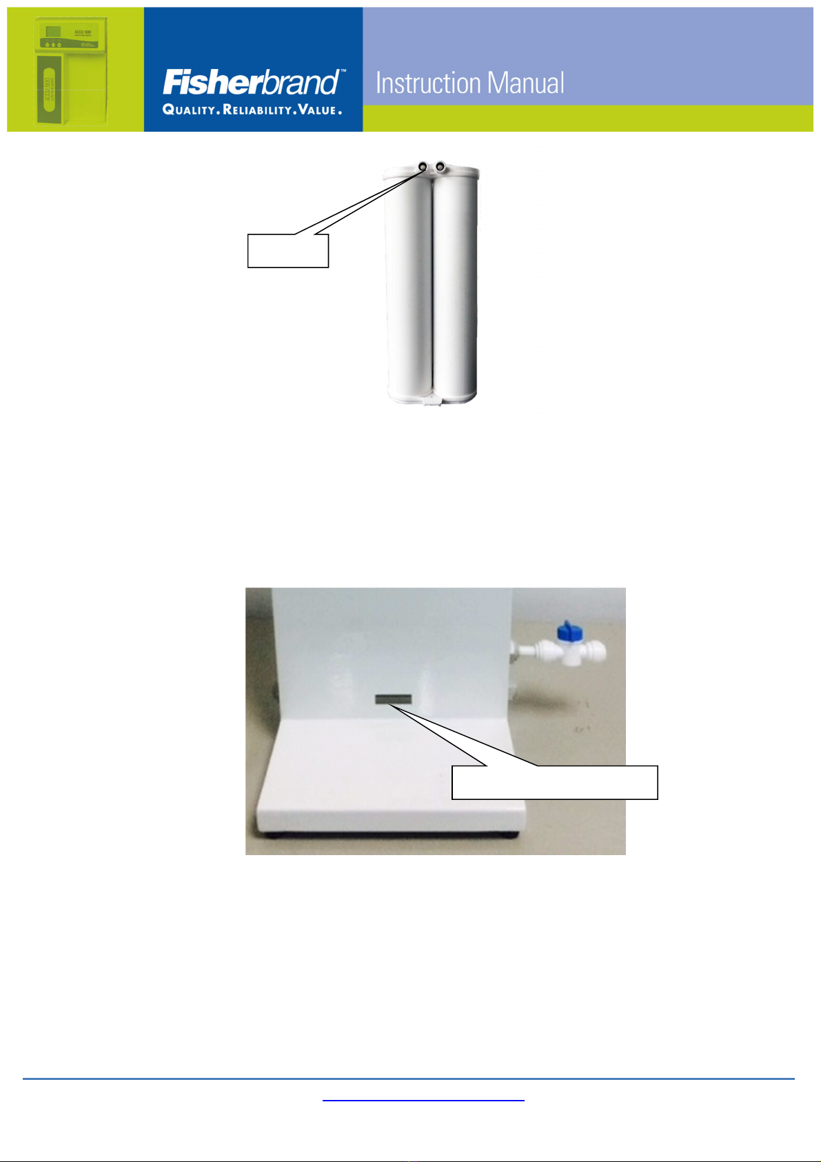
Prefiltration stand (cartridge based) installation
A. Take out the prefiltration system from the package and put it on a
stable platform or firmly hang it on wall.
B. Connect the venting ball valve and the prefiltration system.
C. Connect tap water and water inlet of
prefiltration support by 3/8 inch
tubing with proper length.
D. Connect water outlet of Prefiltration System and pure water system
by 3/8 inch tubing with proper length.
E. Remove the caps from the cartridges and ports of system. Wet the
O-rings on the cartridge with pure water.
Outlet pressure
gauge
Inlet pressure
gauge
Prefilter cartridge
Water inlet
Cartridge lock-pin
and notch location
Air outlet
Water outlet
Prefiltration
support
Venting ball valve
www.eu.fishersci.com/fisherbrand
19
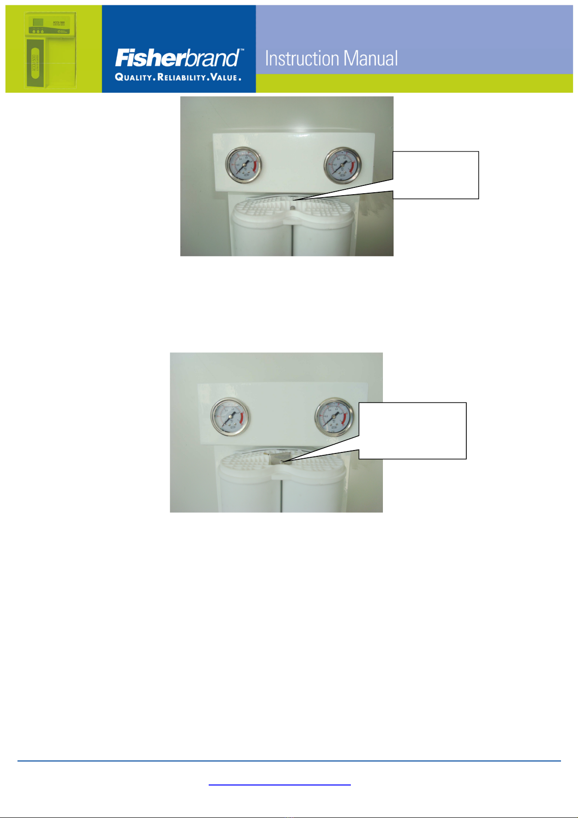
F. Gently insert the lower end first into the opening on the prefiltration
support, then down to let the cartridge sit into its slot.
G. Push the upper part of the cartridge through the lock-pin till tight.
O-ring
Lower Pack Locking Slot
www.eu.fishersci.com/fisherbrand
20
H. Lock the cartridge with the lock-key to the notch on the look-pin.
I. Pressure Relief: Open venting ball valve connected with air outlet;
then turns the tap water on gently to flush out air in PreFilter
Cartridge. Close venting ball valve after degassing.
Cartridge
lock-pin and
notch location
Insert the lock-key
into the notch on
the lock-pin
Other manuals for Accu500
1
This manual suits for next models
10
Table of contents
Other Fisherbrand Laboratory Equipment manuals


Popular Laboratory Equipment manuals by other brands

Home Science Tools
Home Science Tools CE-HOTSTIR manual

Novatech Instruments
Novatech Instruments 1450B instruction manual

Bio-Science
Bio-Science Ampulmatic-10 Purge Gas Injector Operation and maintenance manual

PerkinElmer
PerkinElmer Clarus SQ 8 MS Series Hardware guide

Landi Renzo
Landi Renzo OMEGAS manual

Tripp Lite
Tripp Lite NPOEI-60W-1G quick start guide


