FISNAR EP1320C User manual

EP1320C OPERATION MANUAL
Rev. A - November, 2013
1 | P a g e
CARTRIDGE PUMP
MODEL EP1320C
◀OPERATION MANUAL▶

EP1320C OPERATION MANUAL
Rev. A - November, 2013
2 | P a g e
CONTENTS
1. Safety - - - - - - - - - - - - - - - - - - - - - - - - - 3
2. Introduction - - - - - - - - - - - - - - - - - - - - - - - - - 7
3. Specification - - - - - - - - - - - - - - - - - - - - - - - - 8
4. Control Panel - - - - - - - - - - - - - - - - - - - - - - - - - - - - 9
5. Installation / Set-up / Operation - - - - - - - - - - - - - - - - - - 11
6. Troubleshooting - - - - - - - - - - - - - - - - - - - - - - - - - 14
7. Exploded View / Parts List- - - - - - - - - - - - - - - - - - - - - - 15
8. Dimensions - - - - - - - - - - - - - - - - - - - - - - - - - - 20
9. Technical Data - - - - - - - - - - - - - - - - - - - - - - - - 21
Read the manual before installation and maintenance

EP1320C OPERATION MANUAL
Rev. A - November, 2013
3 | P a g e
SECTION 1
GENERAL SAFETY WARNINGS
1. Equipment Misuse Hazards
Any misuse of the dispensing equipment or accessories such as over-
pressurizing, modifying parts, using incompatible chemicals and fluids, or using
worn or damaged parts, can cause item to rupture and result in fluid splashing in
the eyes or on to the skin.
Never alter or modify any part of this equipment, doing so could cause it to
malfunction.
Check all dispensing equipment regularly and repair, or replace worn or
damaged parts immediately.
Always wear protective eyewear, gloves and clothing, as recommended by the
material and solvent manufacturers.
Never exceed the maximum air inlet pressure of 7 bar (100 psi).
Do not exceed the maximum working pressure of any component or accessory
used in the system.
Be sure that all materials and solvents used are chemically compatible with the
wetted parts. Always read the manufacturer's literature before using material or
solvent in this pump.

EP1320C OPERATION MANUAL
Rev. A - November, 2013
4 | P a g e
2. Hose Safety –High Pressure Hazards
High pressure fluid in the hoses can be very dangerous. If the hose develops a
leak, split or rupture due to any kind of wear, damage or misuse, the high
pressure spray emitted from it can cause material to splash in the eyes or on the
skin. Tighten all fluid connections securely before each use. High pressure fluid
can dislodge a loose coupling or allow high pressure spray to be emitted from the
coupling.
Never use a damaged hose. Before each use, check the entire hose for cuts,
leaks, abrasion or damage or movement of the hose couplings. If any of these
conditions exist, replace the hose immediately.
Do not try to re-couple high pressure hose or mend it with tape or any other
device. A repaired hose cannot safely contain the high pressure fluid.
Handle and route hoses carefully, do not pull on hoses to move equipment. Do
not use materials which are not chemically compatible with the hose.

EP1320C OPERATION MANUAL
Rev. A - November, 2013
5 | P a g e
3. Moving Parts Hazards
In order to lessen the danger of an accident, keep hands and fingers away from
the priming piston while the pump is installed and while air is introduced to the
pump.
Always follow the procedure of depressurizing the system before disassembling
and/or servicing the machine.
The air motor, the fluid area of pump and the motor will move whenever the
machine is activated. Keep hands and fingers away from the air motor during the
priming and installation of the pump.
Keep hands away from the edge of the ram or the pump bracket, hose and pad
plate.
All moving parts are covered by guards. The guards are removable for machine
setting and maintenance. Whenever these guards are removed for setting or
maintenance keep hands clear of any moving parts and pinch hazards.

EP1320C OPERATION MANUAL
Rev. A - November, 2013
6 | P a g e
4. Fire and Explosion Hazards
Static electricity may occur while fluid is in circulation through the pump and hose.
When not properly grounded, a spark may occur which can be dangerous. It can
occur whether the power cord is plugged or not. This spark may ignite any
solvent, dust particles and other combustible materials in or near the machine
and may cause fire, explosion, or serious injuries.
If you are shocked (even by a little) during the installation or normal operation,
stop dispensing immediately. Ground yourself properly to discharge any static
buildup. Do not use the equipment until the problem is completely checked and
safety is secured.

EP1320C OPERATION MANUAL
Rev. A - November, 2013
7 | P a g e
SECTION 2
INTRODUCTION
The EP1320C is a powerful medium ratio system for controlled fluid transfer from 1/10th
gallon (310ml) plastic cartridges –suitable for silicone-type fluids. The system integrates
a dual (A+B) tandem cartridge arrangement for continuous-flow management. A low-
pulse design allows automatic control of dispensing application.
The EP1320C tandem cartridge pump is designed to easily transfer material for
controlled dispensing via a high pressure valve. The suitable viscosity range is
10,000cps –600,000cps.
Rated at 15:1, the system provides a maximum of 995psi regulated material pressure.
The A&B cartridge management automatically switches from either A to B or B to A
when the cartridge is exhausted. Cartridges are contained in metal jacketed cylinders.

EP1320C OPERATION MANUAL
Rev. A - November, 2013
8 | P a g e
SECTION 3
SPECIFICATION
Power Requirements
220VAC ± 10%, 50-60Hz
Power Consumption
10W
Max Air Inlet
9.9kgf/cm2
Pump Ratio
15:1
Weight
18.5kg
Temperature Range
-5oC ~ 40oC
Dimension
272mm (W)
288mm (D)
649mm (H)

EP1320C OPERATION MANUAL
Rev. A - November, 2013
9 | P a g e
SECTION 4
Control Panel

EP1320C OPERATION MANUAL
Rev. A - November, 2013
10 | P a g e
No
Menu
Operation
Description
1
Lamp is on when power on
Lamp is off when power of
Power On/Off switch
2
Lamp On/Off
Cartridge is empty when light
is ON.
3
Indicates which side cartridge
is being used and/or replaced
Pressing Using selects which
cartridge is being used
Pressing Replace indicates
cartridge us being replaced
4
Lamp On/Off
Cartridge is empty when light
is ON.
5
Indicates which side cartridge
is being used and/or replaced
Pressing Using selects which
cartridge is being used
Pressing Replace indicates
cartridge us being replaced
6
Warning sounds
Sounds an alarm when the
material level is low
Replace with a new cartridge
7
Alarm signal out
I/O signal when material is
low.
The contact is broken when
material is low.
EP1320C OPERATION MANUAL
Rev. A - November, 2013
11 | P a g e
SECTION 5
INSTALLATION / SET-UP / OPERATION
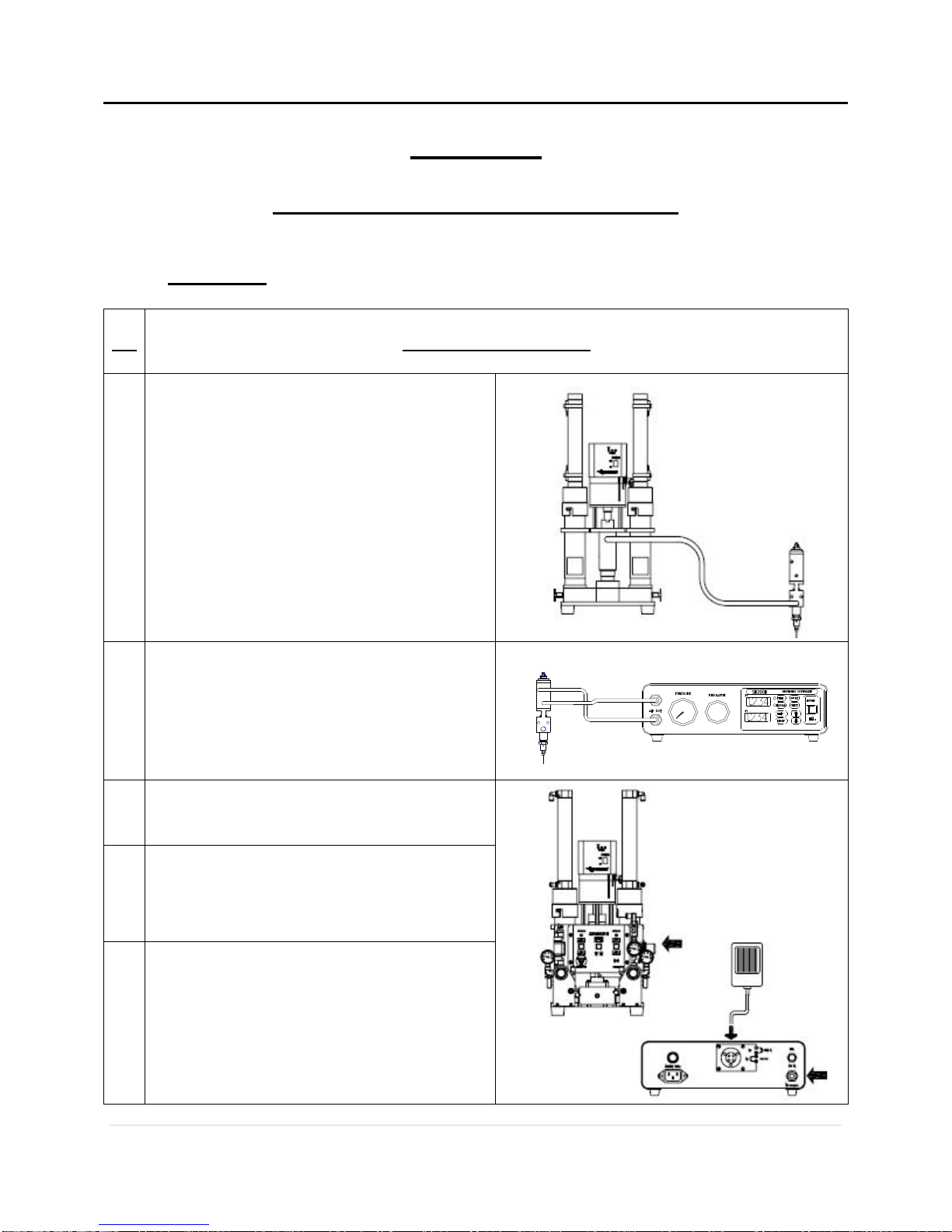
1. Installation
No
Air Line Connections
1
Connect one end of the fluid line to the
fluid inlet of the dispensing valve and
the other to the fluid outlet of the pump.
Please refer to the valve manual for
additional information.
2
Connect air inlet of dispensing valve
and air outlet of controller with connect
tube.
Please refer to the valve and controller
manual for additional information.
3
Connect the air supply to the pump
4
Connect the air supply to the dispensing
controller.
5
Connect the foot pedal to the controller
I/O.
Please refer to the controller manual for
additional information.

EP1320C OPERATION MANUAL
Rev. A - November, 2013
12 | P a g e
2. Set-Up
No
Installing / Replacing the Cartridge
1
Turn the cartridge holder counter
clockwise and pull to remove.
2
Insert the cartridge with the outlet
facing down.
3
Replace the cartridge holder. Turn in
clockwise direction to lock and
secure.

EP1320C OPERATION MANUAL
Rev. A - November, 2013
13 | P a g e
3. Operation
No
Operation
1
Set the main air regulator (A) to the
required dispense pressure.
2
Open the bleed port (C) to extract
bubbles and close slowly.
3
Set air pressure over 30psi with air
regulator (B).
Open the air valve slowly until
material starts flowing.
If the does not stop running, open
the bleed port (D) to let trapped air
out.
Replace the bleed port when
completed.

EP1320C OPERATION MANUAL
Rev. A - November, 2013
14 | P a g e
SECTION 6
TROUBLESHOOTING
ISOLATE ALL AIR AND MATERIAL FEEDS FROM
THE PUMP PRIOR TO SERVICING.
PUMP 접액부의 하부 INTAKE VALVE
(도면 114A, 114B) 마모
분해 세척후 교체
공기통로의 막힘, AIR압력 부족
PUMPING AIR VALVE(도면8번)의 막힘
REGULATOR 작동불량
재료의 잔량 없음
재료 HOSE가 막힘
재료점도가 너무 높아서 PUMPING
할수 없다.
PUMP HEAD부의 MAGNET SENSOR의
위치 이탈
건조된 재료가 PISTON LOAD를 고착
시킴.
PUMP는 작동하지만 유량이 부족하다.
PUMP작동속도가 너무 빠르다.
원인
PUMP의 상승, 하강이 되지 않는다.
배관청소, 공기공급구 점검
AIR VALVE 교체
REGULATOR 교환
SENSOR의 위치 교정
올려본다.
REGULAROR의 AIR 압을
분해 세척후 OIL보충
CARTRIDGE 교환보충
HOSE 교환
보수
PUMP가 작동하지 않는다.
PUMP는 작동하지만 STROKE가 작다.
고장
WARNING
Pump does not work.
Pump stroke is short.
Flow rate is slower than usual
Pump actuates quickly.
Pump does not go up & down.
Probable Cause
Recommended Maintenance
Insufficient air pressure
Defective air valve
Defective regulator pressure
Insufficient material
Clogged hose
Change in material property
Trouble in magnetic sensor
Worn piston rod
Worn intake valve
Clear the air hose
Replace the air valve
Replace the regulator
Replace the cartridge
Replace the hose
Increase the dispense pressure
Adjust the sensor position
Clean and lubricate the rod
Clean and rebuild the valve

EP1320C OPERATION MANUAL
Rev. A - November, 2013
15 | P a g e
SECTION 7
EXPLODED VIEW AND PARTS LIST
1. Main Body

EP1320C OPERATION MANUAL
Rev. A - November, 2013
16 | P a g e
Part No.
Description
Material
Quantity
2
CARTRIGE CAP
AL6061
2
2-A
O-RING
NBR
2
3
SENSER MAGNET
BS
2
4
HOLDER PIPE
STS304
2
5
SENSER MAGNET
BS
3
8
BALL VALVE
BS
1
10
PIN CONNECTOR
STS304
2
12
INLET HOUSING
AL6061
2
13
O-RING
NBR
3
14
MANIFOLD
AL6061
2
15A,B
BLEED COCK
BS
2
25
BLEED COCK
BS
1
27A,B,C
REGULATOR SET
TACO
3
28
ELBOW
BS
1
56
FOOT
BS
4
70
BASE PLATE
AL6061
1
101
CAP
STS
1
102
CYLINDER
AL6061
1
103A,B,C
O-RING
NBR
3
104A,B
PISTON
AL6061
1
106
ROD
SM45C
1
107
WET CUP
STS304
1
109
HOUSING ROD
AL6061
1
110
PRIMING ROD
SM45C
1
112
STOPPER
STS304
1
113
O-RING
NBR
1
114
INTAKE VALVE
ACETAL
1
115
PRIMING ROD
STS304
1
123
PIN
SPRING
1
138
SCREW HEX
BS
3
144
SCREW
STS
1
145
SCREW
STS
1
161
O-RING
NBR
1
162,3
V-PACKING
TEFLON
1
196
HOLDER BRAKET
AL6061
1
196A
BLAKET CLAMP
AL6061
2
EP1320C OPERATION MANUAL
Rev. A - November, 2013
17 | P a g e
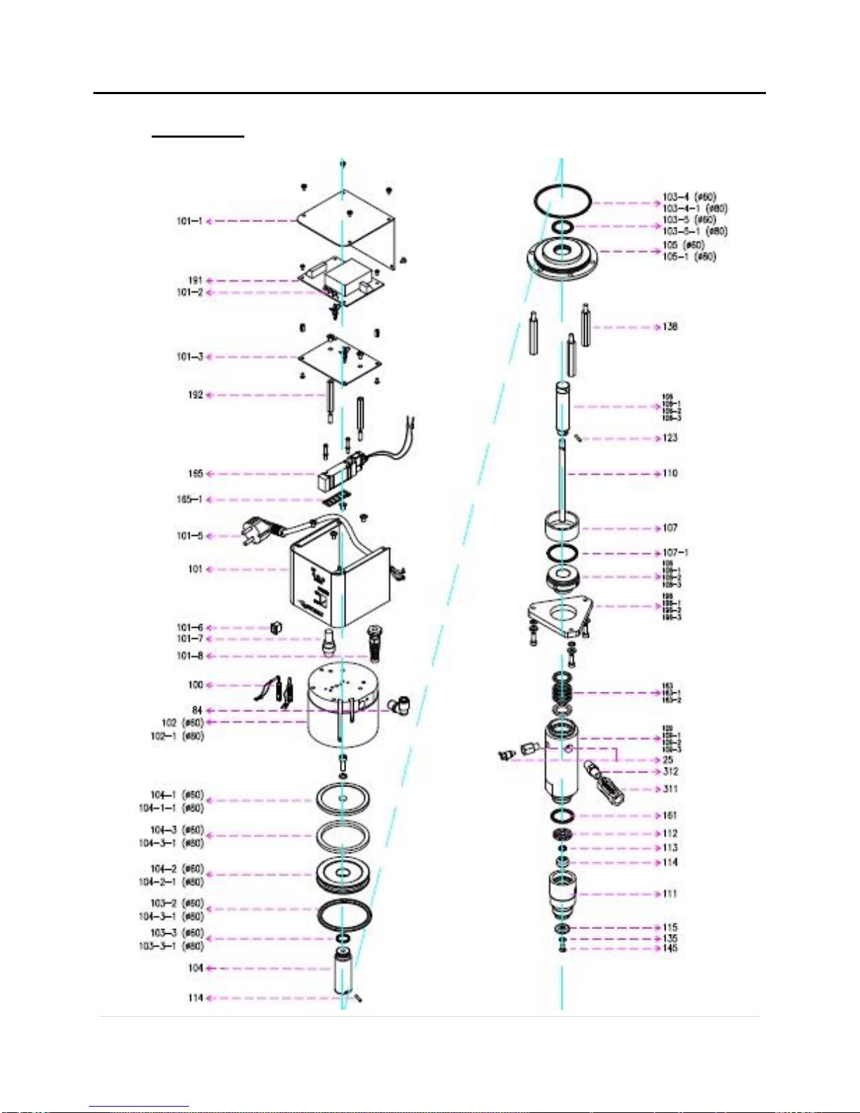
2. Pump Head

EP1320C OPERATION MANUAL
Rev. A - November, 2013
18 | P a g e
Part No.
Description
Size
101-1
PUMP HEAD BOX COVER
191
PUMP HEAD PCB
101-2
LED LAMP(G.Y.R)
192
SPACE BAR-1
M3*10
101-3
PCB PLATE
165
SOLENOID VALVE
SY5140-5LZ(SMC)
101-5
POWER CORD
2P 220V
101
PUMP HEAD BOX COVER
101-6
POWER SWITCH
KCD11(RED)
101-7
FUSE(MEDIUM)
10A 250V AC중(FS-15)
101-8
POWER CORD HOLDER
10A 250V AC
100
PUMP HEAD SENSOR
D-W13(TPC)
102
PUMP HEAD CYLINDER-1
60Ø
102-1
PUMP HEAD CYLINDER-2
80Ø
84
FITTING
KQ2L08-02S
104-1
PUMP HEAD UPPER PISTON
60Ø
104-1-1
PUMP HEAD UPPER PISTON
80Ø
104-2
PUMP HEAD PISTON
60Ø
104-2-1
PUMP HEAD PISTON
80Ø
104-3
PUMP HEAD PISTON MAGNETIC
60Ø
104-3-1
PUMP HEAD PISTON MAGNETIC
80Ø
103-2
O-RING
60Ø
103-2-1
O-RING
80Ø
103-3
O-RING
60Ø
103-3-1
O-RING
80Ø
104
PUMP HEAD CYLINDER SHAFT
144
WITHOUT HEAD BOLT
103-4
O-RING
60Ø
103-4-1
O-RING
80Ø
103-5
O-RING
60Ø
103-5-1
O-RING
80Ø
105
PUMP HEAD CYLINDER UNDER CAP-1
60Ø
105-1
PUMP HEAD CYLINDER UNDER CAP-1
80Ø
140
PUMP HEAD BASE PLATE
60Ø
140-1
PUMP HEAD BASE PLATE
80Ø
138
SUPPORT BAR
106
PUMP SHAFT-1

EP1320C OPERATION MANUAL
Rev. A - November, 2013
19 | P a g e
Part No.
Description
Size
106-1
PUMP SHAFT-2
106-2
PUMP SHAFT-3
106-3
PUMP SHAFT-4
123
SPRING PIN
3Ø, 15
110
PUMP UNDER SHAFT
107
OIL CUP
107-1
O-RING
G40
108
PUMP V-PACKING PUSHER-1
108-1
PUMP V-PACKING PUSHER-2
108-2
PUMP V-PACKING PUSHER-3
108-3
PUMP V-PACKING PUSHER-4
196
PUMP FLUID HOUSING BASE-1
196-1
PUMP FLUID HOUSING BASE-2
196-2
PUMP FLUID HOUSING BASE-3
196-3
PUMP FLUID HOUSING BASE-4
163
PUMP FLUID V-PACKING-1
163-1
PUMP FLUID V-PACKING-2
163-2
PUMP FLUID V-PACKING-3
109
PUMP FLUID HOUSING-1
109-1
PUMP FLUID HOUSING-2
109-2
PUMP FLUID HOUSING-3
109-3
PUMP FLUID HOUSING-4
25
AIR EGEST
161
O-RING
P28(NBR)
112
PUMP FLUID, LOW CHECK STOPPER
113
O-RING
P8N
114
PUMP FLUID LOW CHECK
111
PUMP FLUID UNDER HOUSING
115
PRIMING
135
PLAIN WASHER
M5
145
PLATE HEAD BOLT
M5*10
312
TWO NIPPLE 1/4
1/4 SUS
311
CHECK VALVE 1/4
1/4 (VITON)

EP1320C OPERATION MANUAL
Rev. A - November, 2013
20 | P a g e
SECTION 8
DIMENSIONS
Table of contents
Popular Water Pump manuals by other brands


Sears
Sears CRAFTSMAN 390.269152 owner's manual

Pentair
Pentair Myers MSK60 Installation and operator's manual

Becker
Becker VariAir VASF 2.50/1-0.AC230 BASIC operating instructions

hecht
hecht 3635 TRANSLATION OF ORIGINAL INSTRUCTIONS FOR USE

FloJak
FloJak F-50 Instructions & assembly

Wayne
Wayne 352205-001 Operating instructions and parts manual

Nocchi
Nocchi BIOX 200/8 manual

Pfeiffer Vacuum
Pfeiffer Vacuum UnoLine UNO 35 Translation of the original operating instructions

Grundfos
Grundfos SL Series Installation and operating instructions

Koshin
Koshin SEH-50X instruction manual

BUSCH
BUSCH COBRA ATEX NC 2000 B VR instruction manual

Silverline
Silverline 104616 quick start guide