FiT REMOTE DISPLAY User manual
INSTRUCTION MANUAL
Biketec GmbH
Luzernstrasse 84
CH-4950Huttwil
T +41 62 959 53 00
info@biketec.ch
fit-ebike.com
NETWORKED
CUSTOMISED
INTELLIGENT
500093 | 501103 | 501263 | 501264
FIT REMOTE DISPLAY
PINION

INSTRUCTION MANUAL FIT REMOTE DISPLAY PINION
TABLE OF CONTENTS
1 PREFACE 4
2 ABOUT THESE OPERATING INSTRUCTIONS 5
2.1 MANUFACTURER................................................. 5
2.2 LANGUAGE..................................................... 5
2.3 DECLARATIONOFCONFORMITY ........................................ 5
2.4 ONINFORMATION ................................................ 5
2.5 WARNINGS IN THESE OPERATING INSTRUCTIONS . . . . . . . . . . . . . . . . . . . . . . . . . . . . . . 5
3 SAFETY INSTRUCTIONS 6
3.1 GENERALINFORMATION............................................. 6
3.2 OPERATINGELEMENTANDDISPLAY...................................... 6
4 PRODUCT AND TECHNICAL SPECIFICATIONS 7
4.1 FITREMOTEDISPLAY............................................... 7
4.1.1 DISPLAYANDSETTINGS......................................... 7
4.2 OPERATINGELEMENT .............................................. 8
4.2.1 PINIONTE1E-TRIGGER......................................... 9
4.3 PROPERUSE ................................................... 10
4.4 IMPROPERUSE.................................................. 10
4.5 TECHNICALDATA................................................. 10
4.5.1 FITREMOTEDISPLAY .......................................... 10
5 TRANSPORTATION AND STORAGE 11
5.1 TRANSPORTATION ................................................ 11
5.1.1 TRANSPORTINGE-BIKES........................................ 11
5.2 STORAGE...................................................... 11
5.3 BREAKINOPERATION .............................................. 11
5.3.1 CARRYING OUT A BREAK IN OPERATION . . . . . . . . . . . . . . . . . . . . . . . . . . . . . . . 11
6 OPERATION 12
6.1 INITIALOPERATION................................................ 12
6.1.1 ELECTRICDRIVESYSTEM........................................ 12
6.1.2 PAIRING / COUPLING THE FIT KEY CARD WITH THE FIT E-BIKE CONTROL APP . . . . . . . . . 12
6.1.3 ASSISTANCEMODES .......................................... 13
6.1.4 PUSHINGAID............................................... 14
6.1.5 BOOSTFUNCTION............................................ 14
6.2 LIGHTING ..................................................... 14
6.3 ESHIFT....................................................... 15
6.4 WARNING/ERRORSYMBOLS.......................................... 15
6.5 SELECTIONSCREEN ............................................... 15
6.6 MAIN/SUB-SCREENS.............................................. 16
6.6.1 NAVIGATION ............................................... 19
6.7 CHARGEINDICATOR ............................................... 23
7 SETTINGS MENU 25
7.1 REMOTEDISPLAY................................................. 25
7.2 MENUSTRUCTURE................................................ 26
7.3 SETTINGOPTIONS ................................................ 27
7.4 ESHIFTSETTINGS................................................. 30
7.4.1 PINIONMGU/ESHIFT.......................................... 30
8 ERROR MESSAGES 32
8.1 GENERALINFORMATION............................................. 32
8.2 STATUS LED ON OPERATING ELEMENT AND DISPLAY . . . . . . . . . . . . . . . . . . . . . . . . . . . . 32
8.3 INFORMATION/ERRORDISPLAY........................................ 32
8.3.1 ERRORTABLE .............................................. 34
FIT_Manual_Remote_Display_Pinion_V3_en | Version 03 | 24.10.2023 2

INSTRUCTION MANUAL FIT REMOTE DISPLAY PINION
9 CLEANING AND SERVICING 50
9.1 BASICCLEANING ................................................. 50
9.1.1 CLEANING THE DISPLAY AND OPERATING ELEMENT . . . . . . . . . . . . . . . . . . . . . . . . 50
10 TROUBLESHOOTING, FAULT CLEARANCE AND REPAIR 51
10.1 TROUBLESHOOTING AND FAULT CLEARANCE . . . . . . . . . . . . . . . . . . . . . . . . . . . . . . . . . 51
10.1.1 DRIVE SYSTEM OR DISPLAY DOES NOT START UP . . . . . . . . . . . . . . . . . . . . . . . . . . 51
10.1.2 ERRORS IN THE ASSISTANCE SYSTEM . . . . . . . . . . . . . . . . . . . . . . . . . . . . . . . . 51
10.2REPAIR....................................................... 52
10.2.1ORIGINALPART ............................................. 52
10.2.2REPLACINGTHELIGHTS ........................................ 52
10.2.3ADJUSTINGTHEHEADLIGHT ...................................... 52
11 RECYCLING AND DISPOSAL 53
11.1DISPOSAL ..................................................... 53
FIT_Manual_Remote_Display_Pinion_V3_en | Version 03 | 24.10.2023 3

INSTRUCTION MANUAL FIT REMOTE DISPLAY PINION
1 PREFACE
Dear FIT customer,
The FIT system offers many useful functions and options and we are pleased that you have decided to choose our
system.
Please read through the operating instructions carefully to ensure you use the system safely and get off to a quick
start.
We hope you enjoy discovering the FIT’s functions and have a fun ride every time you use it.
Thank you for placing your trust in FIT.
Your FIT Team
FIT_Manual_Remote_Display_Pinion_V3_en | Version 03 | 24.10.2023 4

INSTRUCTION MANUAL FIT REMOTE DISPLAY PINION
2 ABOUT THESE OPERATING INSTRUCTIONS
2.1 MANUFACTURER
Biketec GmbH
Luzernstrasse 84
CH-4950 Huttwil
fit-ebike.com/en-en/
2.2 LANGUAGE
The original operating instructions are written in German. A translation is invalid without the original operating in-
structions.
2.3 DECLARATION OF CONFORMITY
Biketec GmbH hereby declares that the products described in these operating instructions comply with EU directives.
The complete EU Declaration of Conformity is available online at: fit-ebike.com/en-en/service/declaration/
2.4 ON INFORMATION
Different markings are used in the operating instructions to make them easier to read.
2.5 WARNINGS IN THESE OPERATING INSTRUCTIONS
Warnings indicate hazardous situations and actions. You will find the following warnings in the operating instructions:
DANGER
May lead to serious or even fatal injuries if ignored. Medium-risk hazard.
CAUTION
May lead to minor or moderate injuries if ignored. Low-risk hazard.
NOTICE
May lead to material damage if ignored.
FIT_Manual_Remote_Display_Pinion_V3_en | Version 03 | 24.10.2023 5

INSTRUCTION MANUAL FIT REMOTE DISPLAY PINION
3 SAFETY INSTRUCTIONS
3.1 GENERAL INFORMATION
Please read all safety instructions carefully. Failure to comply with the warnings or take residual risks into account
may result in electric shock, fire and / or serious injury.
Keep the operating instructions in a safe place and have them readily available to consult. Pass these instructions
on if you provide your e-bike for someone else’s use.
The generic names used in these operating instructions, such as motor, battery and operating element, all refer to
original FIT e-bike components.
3.2 OPERATING ELEMENT AND DISPLAY
Do not let the messages on the display screen distract you. If you do not focus solely on traffic on the road, you risk
being involved in an accident.
Do not open up the operating element or the display. They both can be permanently damaged if they are opened
and the warranty will become void.
Do not use the display as a handle. If you use the display to lift your e-bike, you can damage the display irreparably.
Do not place the e-bike upside down on its handlebars and saddle if the display or its mount project above the
handlebars. The display or the mount can become irreparably damaged. Also remove the display before placing the
e-bike on a work stand to ensure that the display does not fall off or get damaged.
Caution! If you use the operating element with Bluetooth, it may cause interference with other devices and equip-
ment, aircraft, and medical devices, such as pacemakers and hearing aids. Likewise, it cannot be completely ruled
out that you will cause harm to people and animals in the immediate vicinity. Avoid operating close to your body
for extended periods of time. You must observe local restrictions on using Bluetooth when in aircraft or hospitals, for
example, or in close proximity to medical devices, filling stations, chemical plants, blasting zones and areas at risk of
explosion.
FIT_Manual_Remote_Display_Pinion_V3_en | Version 03 | 24.10.2023 6

INSTRUCTION MANUAL FIT REMOTE DISPLAY PINION
4 PRODUCT AND TECHNICAL SPECIFICATIONS
4.1 FIT REMOTE DISPLAY
The elegant and compact design of the FIT Remote Display ensures a tidy, minimalist cockpit. All the relevant
information can be seen at a glance, with no distractions. The combination of control unit and display shows the
same content as the FIT displays and is easy to use without taking your hands off the handlebars. The FIT Drive
Screen can be conveniently controlled via the FIT Remote Display. This additional function is available in the FIT
E-Bike Control app.
4.1.1 DISPLAY AND SETTINGS
The following display elements remain the same on all screens (except DRIVE) and show the key settings and
information about the vehicle and the current trip.
1. Notice / danger alert messages (only the symbol indicating the top priority is displayed
if there is more than one notice / danger alert message).
2. Current speed
3. Current level of assistance
4. Light (main beam / dimmed headlight / off)
5. eShift gear indicator
FIT_Manual_Remote_Display_Pinion_V3_en | Version 03 | 24.10.2023 7

INSTRUCTION MANUAL FIT REMOTE DISPLAY PINION
4.2 OPERATING ELEMENT
Operating
element Description
On-Off button
Rocker switch (right, left and press)
Plus / minus button
Push assist / boost button
Light button
FIT_Manual_Remote_Display_Pinion_V3_en | Version 03 | 24.10.2023 8
INSTRUCTION MANUAL FIT REMOTE DISPLAY PINION
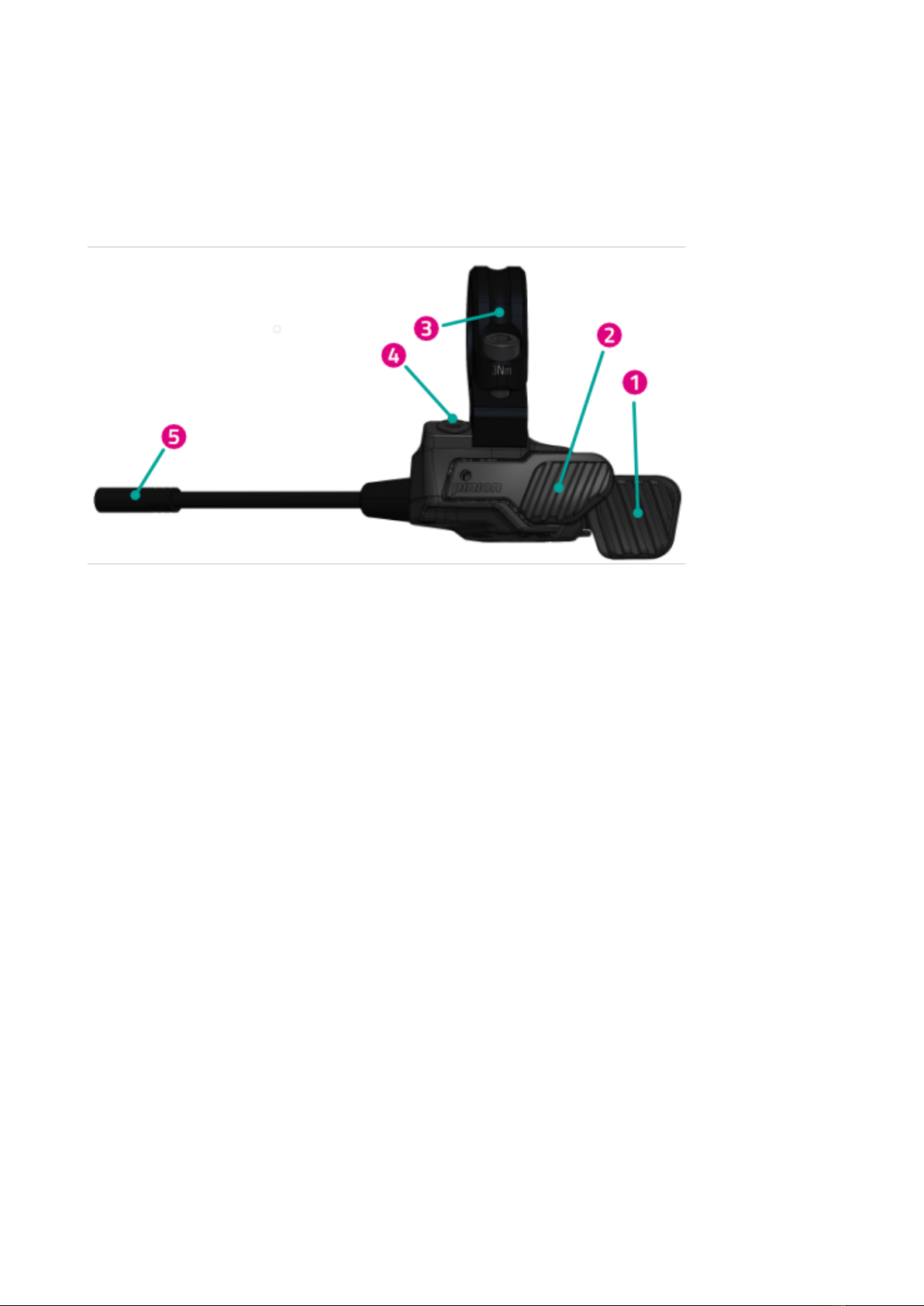
4.2.1 PINION TE1 E-TRIGGER
The compact Pinion TE1 e-trigger gear lever has been specially developed for shifting with Pinion Smart.Shift shift
technology. The goal was to provide clear haptic feedback. With a defined lever path and sophisticated micro button
tuning, you can precisely initiate each shifting process. Maintenance-free and waterproof as defined by IP66, the
TE1 is the optimal control in every situation.
1. Rear gear lever
2. Front gear lever
3. Blind screw
4. Matchmaker clamp with screw
5. Plug
FIT_Manual_Remote_Display_Pinion_V3_en | Version 03 | 24.10.2023 9

INSTRUCTION MANUAL FIT REMOTE DISPLAY PINION
4.3 PROPER USE
The operating element and the display are designed to control a FIT e-bike system and display trip data.
4.4 IMPROPER USE
Improper use refers to use which is not described under proper use or goes beyond proper use.
4.5 TECHNICAL DATA
4.5.1 FIT REMOTE DISPLAY
Display FIT REMOTE DISPLAY
Product code 500093 (cable length 450mm, without spacer)
501103 (cable length 800mm, without spacer)
501263 (cable length 450mm, with spacer)
501264 (cable length 800mm, with spacer)
Operating temperature °C -5 Up to +40
Storage temperature °C -10 Up to +50
Protection class IPX7
Weight about kg 0,1
FIT_Manual_Remote_Display_Pinion_V3_en | Version 03 | 24.10.2023 10

INSTRUCTION MANUAL FIT REMOTE DISPLAY PINION
5 TRANSPORTATION AND STORAGE
5.1 TRANSPORTATION
CAUTION
Remove battery before transportation.
There is a risk of injury if the drive system is switched on unintentionally.
5.1.1 TRANSPORTING E-BIKES
Protect the electrical components and connections on the e-bike from the elements with suitable protective covers.
5.2 STORAGE
CAUTION
Store e-bike, display, battery and charger in a clean, dry place where they are protected from sun-
light. Do not store outdoors to ensure a long service life.
The optimum storage temperature for your e-bike is between 10 °C and 20 °C.
Temperatures under -10 °C or over +40 °C must generally be avoided.
Store e-bike, display, battery and charger separately.
5.3 BREAK IN OPERATION
If you remove the e-bike from service for longer than four weeks, you need to prepare it for a break in operation.
5.3.1 CARRYING OUT A BREAK IN OPERATION
Store the e-bike, battery and charger in a dry, clean environment. We recommend storing them in uninhabited rooms
with smoke alarms. Dry locations with an ambient temperature between 10 and 20 °C are ideal.
FIT_Manual_Remote_Display_Pinion_V3_en | Version 03 | 24.10.2023 11
INSTRUCTION MANUAL FIT REMOTE DISPLAY PINION
6 OPERATION
6.1 INITIAL OPERATION
6.1.1 ELECTRIC DRIVE SYSTEM
SWITCHING ON THE ELECTRIC DRIVE SYSTEM The system can only be switched on if a sufficiently charged battery
and the display are inserted.
Press the On-Off button for at least one second to switch on the system. The «Drive» menu is shown on the display
screen.
SWITCHING OFF THE ELECTRIC DRIVE SYSTEM The drive system switches off automatically to save energy if no
rider activity is detected for a longer period of time. (The rider can adjust the time interval until switch-off in the
settings menu -> MyBike -> Auto Power Off.) The display is operated using the rocker switch on the operating element
so that your hands can remain on the handlebars while you are riding.
Press the On-Off button for at least a second to switch off the electric system by hand.
OPERATION You can access the different main screens using the rocker switch (left / right). The settings menu can
only be accessed when the e-bike is stationary. An overview of all main screens is displayed each time the rocker
switch is used to make operation simpler. This allows you to select the required screen directly without needing to
go through all the different screens first. Either press the rocker switch or wait briefly to enter the required screen
(if the rocker switch is not moved for more than 1 sec., you enter the selected screen automatically). You can press
the rocker switch while in any screen except the Drive screens or the settings menu to enter the main Drive screen
directly. In the drive screens, you can use the rocker switch to scroll through the individual screens.
You can use plus / minus to scroll up and down a list you have accessed, such as the Settings menu. If the light button
and the rocker switch (press) have a new function (OK, Back), this is shown on the display.
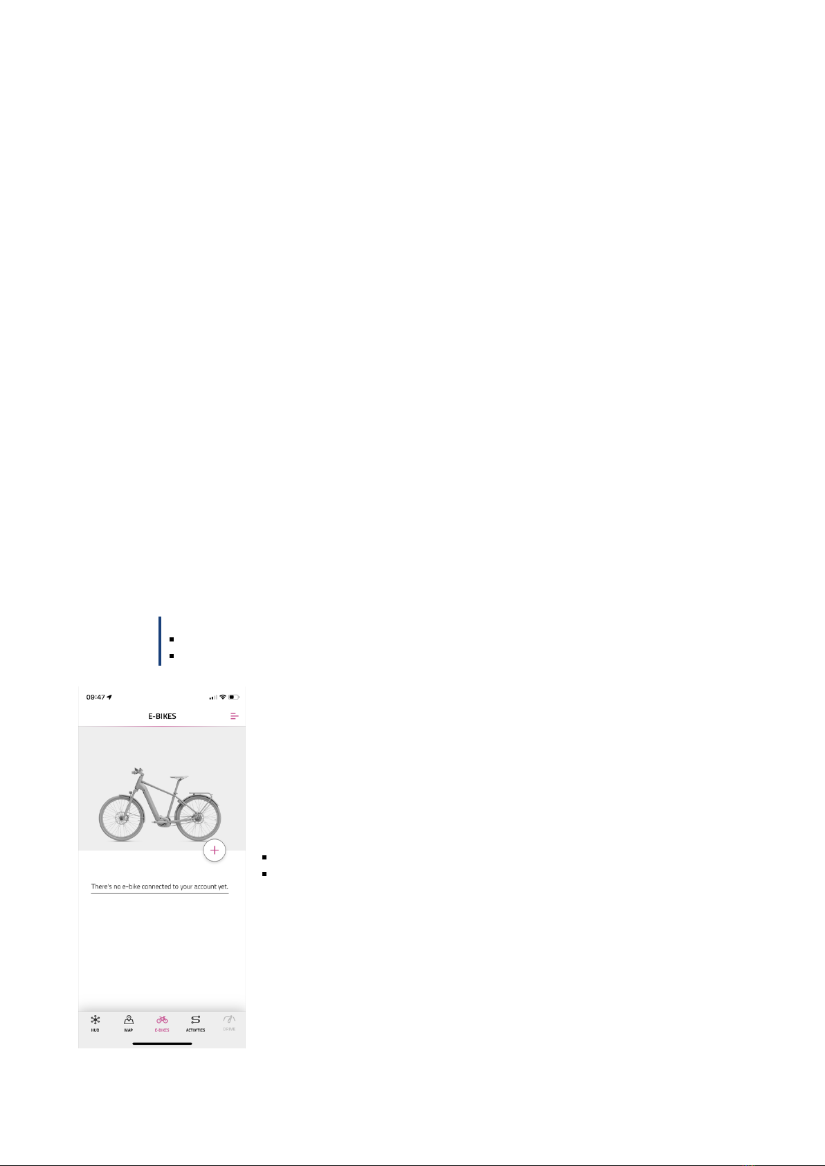
6.1.2 PAIRING / COUPLING THE FIT KEY CARD WITH THE FIT E-BIKE CONTROL APP
The FIT Key Card is your ticket to the digital FIT world for every e-bike with FIT 2.0 integration. The individual ID is
based on the SmartX technology from ABUS and ensures a secure connection to the e-bike with a unique key.
NOTICE
Keep the card in a safe place as it serves as the e-bike’s ID.
Can be reordered subject to payment in the e-shop if lost.
Select the menu E-bikes in the navigation bar
Press the +icon to add your e-bike in the FIT E-Bike Control app
FIT_Manual_Remote_Display_Pinion_V3_en | Version 03 | 24.10.2023 12
INSTRUCTION MANUAL FIT REMOTE DISPLAY PINION
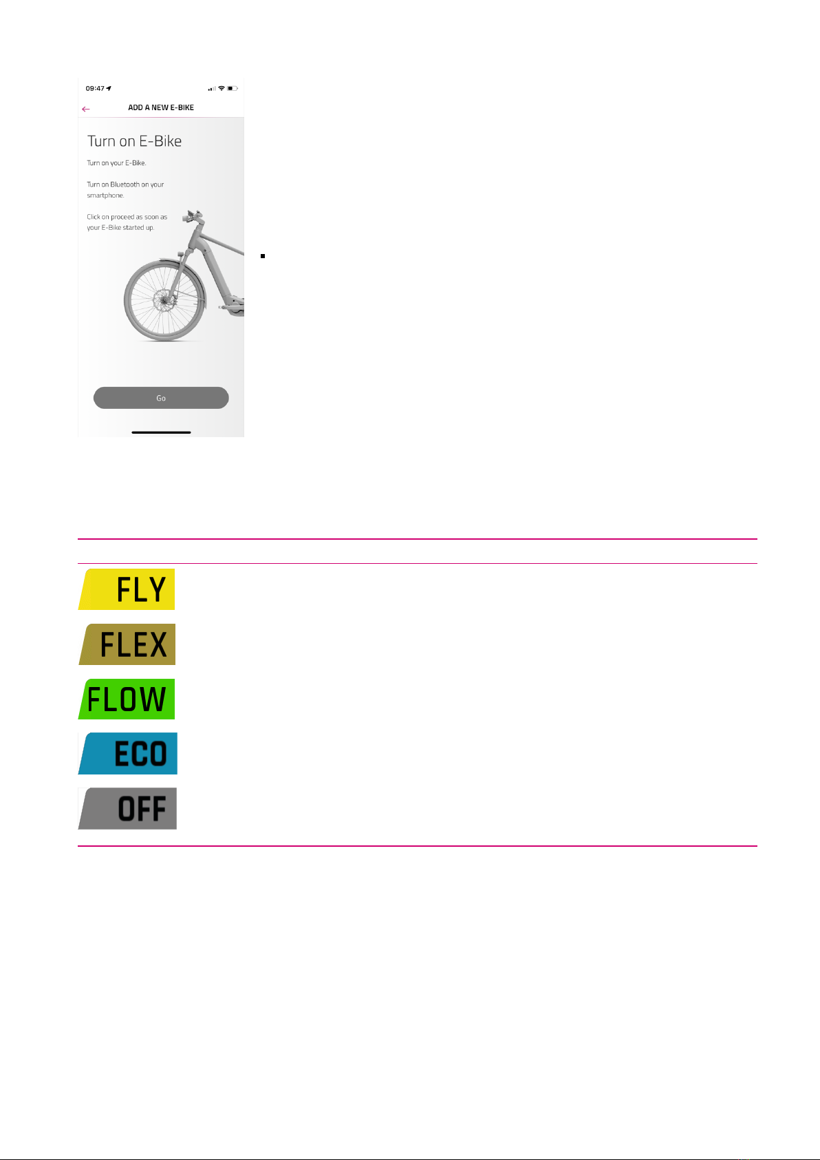
Follow the instructions in the FIT E-Bike Control app
6.1.3 ASSISTANCE MODES
You can set the assistance levels using the + and – buttons on the control unit.
Symbol Description
Maximum motor assistance for active riding up to high pedaling frequencies.
Motor assistance is perfect for E-MTB trails or very agile e-bikes.
Motor assistance for energy-saving cross-country trips or moderate off-road terrain.
Minimal motor assistance with optimum efficiency for maximum range.
No motor assistance. The e-bike rides like a normal bicycle. All on-board computer functions are
available.
FIT_Manual_Remote_Display_Pinion_V3_en | Version 03 | 24.10.2023 13
INSTRUCTION MANUAL FIT REMOTE DISPLAY PINION
6.1.4 PUSHING AID
Assistance mode icon:
The pushing aid makes it easier to push the e-bike. The e-bike can be moved out of underground parking or along
steep paths comfortably by activating the pushing aid.
Briefly press the pushing aid / boost button to activate pushing aid mode. Press again to start the pushing aid.
If you release the pushing aid / boost button for more than five seconds, you will leave pushing aid mode. Pushing
aid speed can be adjusted via the settings menu.
While using the pushing aid, the pushing aid speed can be temporarily reduced / increased via the buttons on the TE1
trigger.
CAUTION
When using the pushing aid, the wheels must be in contact with the ground, otherwise there is a risk
of injury.
6.1.5 BOOST FUNCTION
Assistance mode icon:
The Boost function can be used to briefly increase motor support to FLY level regardless of the selected assistance
level (ECO, FLOW, FLEX). This function can be activated at speeds of 7 km/h and over and if at least one quarter pedal
revolution has been detected. The Boost function cannot be used if the pushing aid mode is active.
Press the Pushing aid / Boost button to activate the Boost function. The Boost function is activated as long as the
button is held down.
6.2 LIGHTING
You can use the light button to switch between the following lighting modes (availability depends on the model):
Symbol Description
Dimmed headlight
Main beam
Light off
Different lighting systems are fitted depending on the bike type and field of use. If the system features a daytime
running light function, the bike switches between the dimmed and daytime running lights automatically.
The dimmed headlight is permanently activated on S pedelecs because of EU directives. Pressing the light button will
activate or deactivate the main beam as well.
FIT_Manual_Remote_Display_Pinion_V3_en | Version 03 | 24.10.2023 14

INSTRUCTION MANUAL FIT REMOTE DISPLAY PINION
6.3 ESHIFT
You can select the gear shift manually with the up / down button.
Symbol Description
Current selected speed
Gear recommendation – change up a
gear
Gear recommendation – change down a
gear
6.4 WARNING / ERROR SYMBOLS
Symbol Meaning Action / Limitation
Ice hazard
(temperature ≤4 °C) Drive carefully.
Maintenance request Your e-bike should be taken to the FIT specialist dealer for
maintenance as soon as possible.
Motor overheat Reduced ride assistance performance. (This is not an error, but is
meant to protect the motor.)
Battery protection
mode (battery level
and / or temperature
too low)
Reduced ride assistance performance. (This is not an error, but is
meant to protect the battery.)
Low tire pressure Check and adjust the tire pressure if necessary. (This function is only
available with optional tire pressure sensors.)
Info
Motor assistance available
The message can be acknowledged by pressing the rocker switch.
(For more information, see section 8.3.1)
Warning
Motor assistance available
The message can be acknowledged by pressing the rocker switch.
(For more information, see section 8.3.1)
Error / Critical error
No motor assistance
Motor assistance is only available once the error has been rectified
and the system has been restarted (only in the case of a critical error).
(For more information, see section 8.3.1)
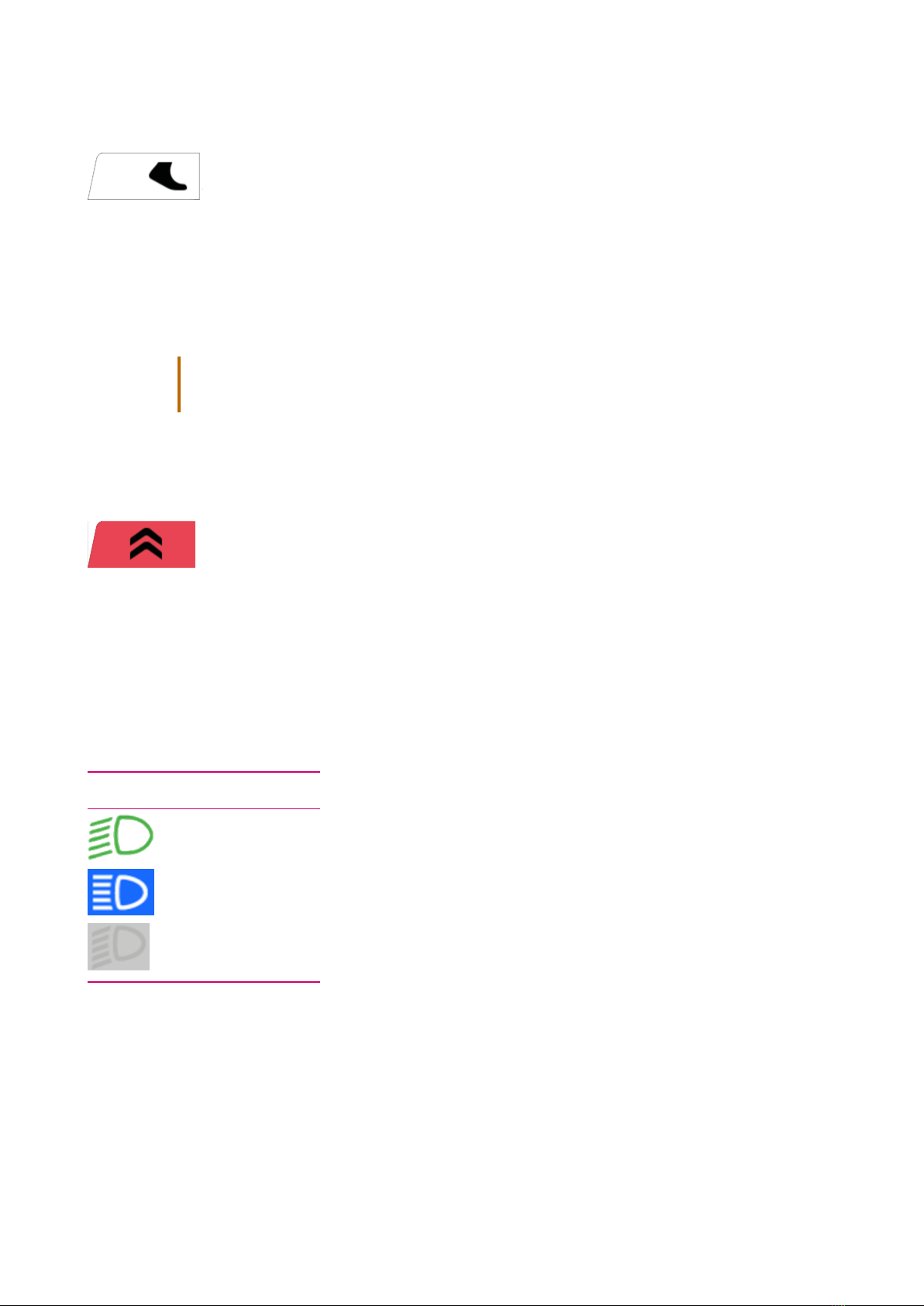
6.5 SELECTION SCREEN
You can access the different main screens using the rocker switch (left / right). An overview of all main screens
is displayed each time the rocker switch is used to make operation simpler. This allows you to select the required
FIT_Manual_Remote_Display_Pinion_V3_en | Version 03 | 24.10.2023 15
INSTRUCTION MANUAL FIT REMOTE DISPLAY PINION
screen directly without needing to go through all the different screens first. Either press the rocker switch or wait
briefly to enter the required screen (if the rocker switch is not moved for more than 1 sec., you enter the selected
screen automatically). You can press the rocker switch while in any screen except the Drive screens or the settings
menu to enter the main Drive screen directly. In the drive screens, you can use the rocker switch to scroll through the
individual screens.
SELECTION DISPLAY PAGE 1
1. Name of the screen currently selected (symbol highlighted with colour)
2. The settings menu (can only be accessed when the e-bike is stationary.)
3. Main Drive screen
4. Trip distance – distance ridden during the current trip
5. Trip time – duration of the current trip
6. Trip altitude – difference in altitude ridden during the current trip
7. Total - odometer
8. Altitude – current altitude
9. Cadence – current pedalling rate
10. Pulse – current heart rate
11. Page status bar
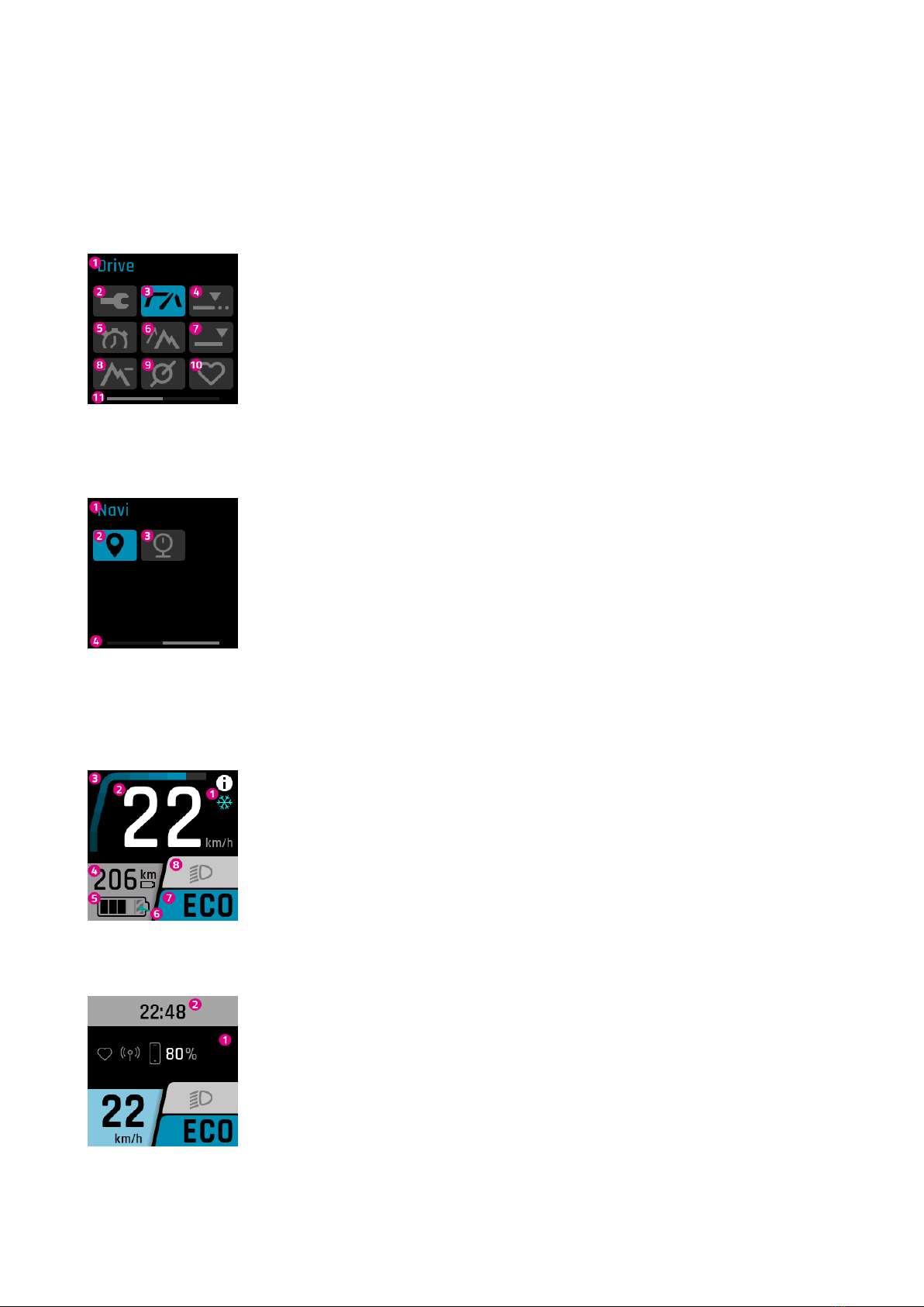
SELECTION DISPLAY PAGE 2
1. Name of the screen currently selected (symbol highlighted with colour)
2. Navi - navigation
3. Pressure – current tire pressure
4. Page status bar
6.6 MAIN / SUB-SCREENS
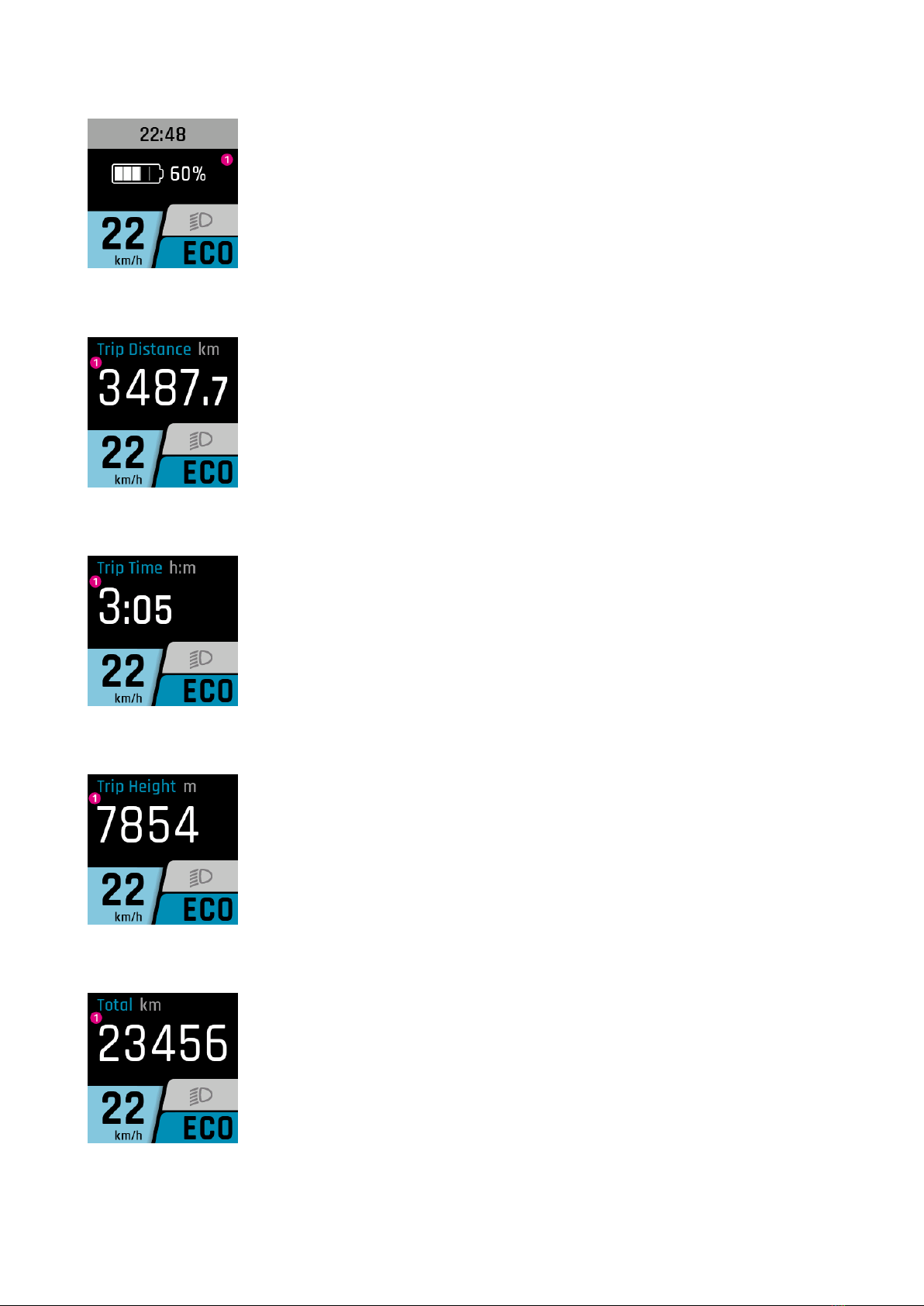
DRIVE MAIN DISPLAY
1. Notice / danger alert messages
2. Current speed
3. Current motor assistance
4. Range (in current assistance setting / level of assistance)
5. Battery level
6. The hatched part indicates that the battery is in Long Life mode.If Long Life mode is
deactivated, the hatching disappears. (For more information, see Section 6.7)
7. Current level of assistance
8. Light (main beam / dimmed headlight / off)
DRIVE SUB DISPLAY
1. Linked devices (heart rate sensor, smartphone, including smartphone battery charge
level)
2. Clock
FIT_Manual_Remote_Display_Pinion_V3_en | Version 03 | 24.10.2023 16
INSTRUCTION MANUAL FIT REMOTE DISPLAY PINION
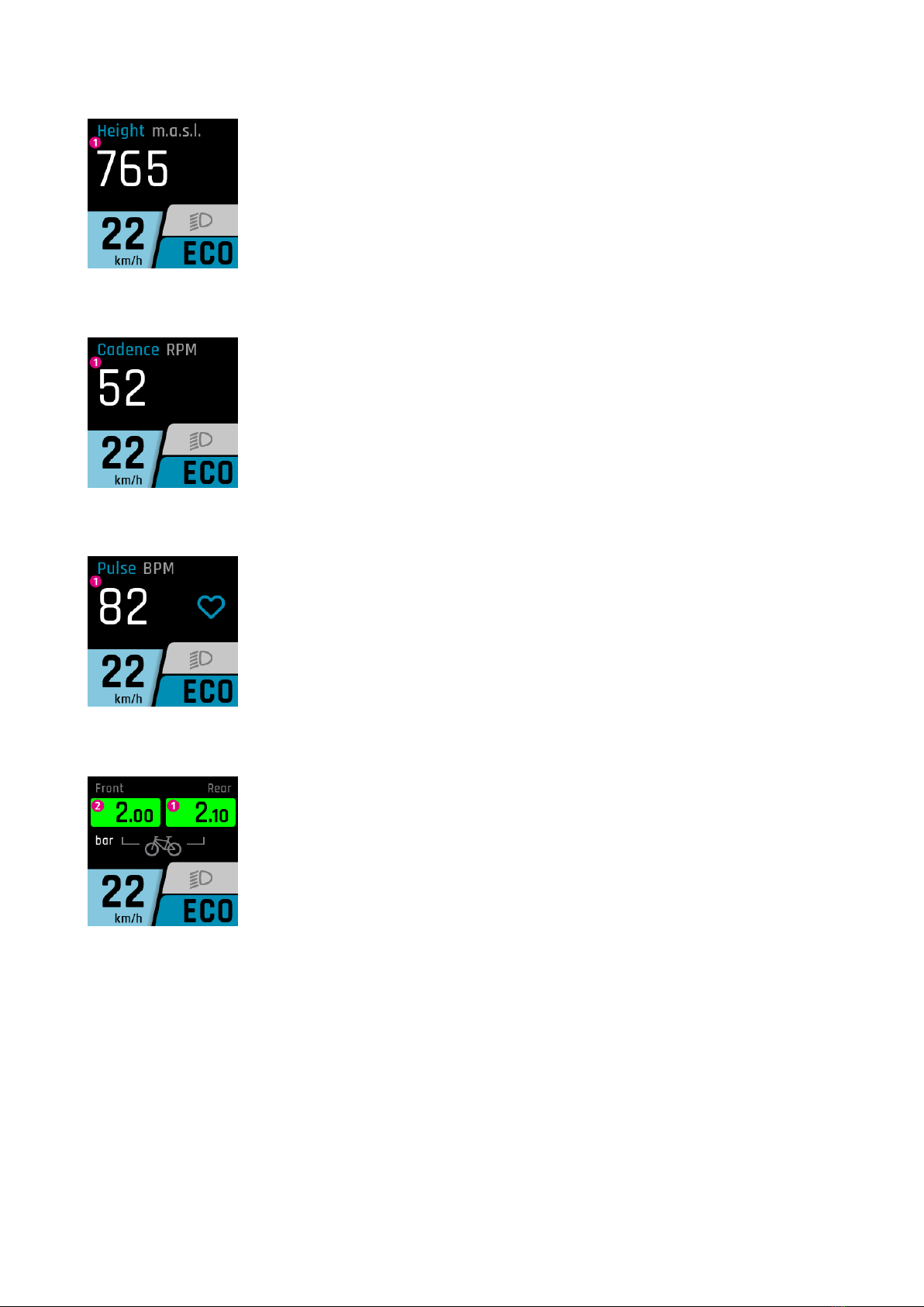
DRIVE SUB DISPLAY 2
1. Battery charge level (if there is more than one battery, they are all displayed and are
numbered consecutively)
TRIP DISTANCE
1. Distance ridden during the current trip
TRIP TIME
1. Duration of the current trip
TRIP HEIGHT
1. Difference in altitude ridden during the current trip
TOTAL
1. Odometer (total number of kilometres that the e-bike has covered. This value cannot
be reset.)
FIT_Manual_Remote_Display_Pinion_V3_en | Version 03 | 24.10.2023 17
INSTRUCTION MANUAL FIT REMOTE DISPLAY PINION
HEIGHT
1. Current altitude
Since the indicated altitude depends on the air pressure, the incorrect altitude may
be displayed if the altimeter is not calibrated on a regular basis. Calibration should be
carried out at the point of departure as a minimum.
CADENCE
1. Current pedal speed
PULSE
1. Current pulse (only available in conjunction with a heart rate sensor)
PRESSURE (only available with an optional tire pressure sensor)
1. Current tire pressure, rear
2. Current tire pressure, front
FIT_Manual_Remote_Display_Pinion_V3_en | Version 03 | 24.10.2023 18
INSTRUCTION MANUAL FIT REMOTE DISPLAY PINION
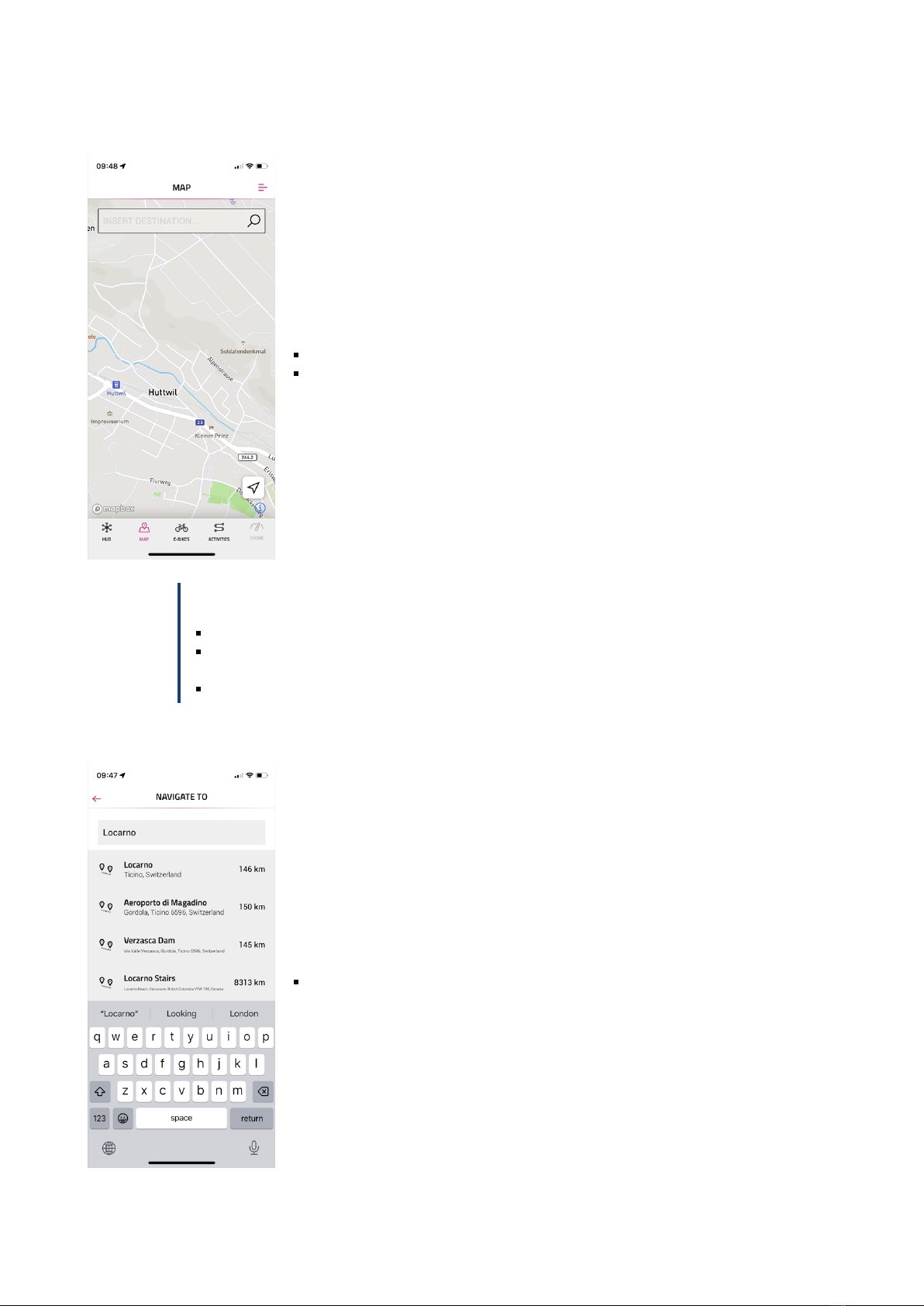
6.6.1 NAVIGATION
Navigation is only available in conjunction with the FIT E-Bike Control app. To use the FIT E-Bike Control app, the
smartphone must be connected to the e-bike using the FIT Key Card (see section 6.1.2).
There are two types of navigation available:
MAP: Direct destination entry and navigation in the FIT E-Bike Control app.
ACTIVITIES: Tour records and planned tours of the connected komoot account can
be displayed here. Navigation is available on all routes under Planned Tours.
NOTICE
To use the navigation function, you must observe the following points:
The e-bike must be switched on and connected to the smartphone.
To ensure the connection (Bluetooth) between the e-bike and the FIT E-Bike Control app, the
smartphone and e-bike must be no more than five meters apart.
The e-bike must be linked to the FIT E-Bike Control app (see section 6.1.2).
Navigate to:
Enter the desired navigation destination.
FIT_Manual_Remote_Display_Pinion_V3_en | Version 03 | 24.10.2023 19

INSTRUCTION MANUAL FIT REMOTE DISPLAY PINION
After entering the start and end point, information about the selected route is dis-
played:
1. Distance to the target.
2. The red battery symbol indicates that the current charging status is not sufficient
to reach the destination in any assistance level.
3. Current range in the various assistance levels (the black bar shows the assistance
level currently selected on the e-bike).
Navigation can be started with START.
In the ACTIVITIES menu, you can choose between recorded and planned tours from
the linked komoot account.
The last route is also available as a speed dial.
NOTICE
After linking your komoot account for the first time, it will take a while for all planned tours to be
synchronized.
FIT_Manual_Remote_Display_Pinion_V3_en | Version 03 | 24.10.2023 20
This manual suits for next models
6
Table of contents
Other FiT Bicycle Accessories manuals


Popular Bicycle Accessories manuals by other brands


Xtracycle
Xtracycle PeaPod LT User's guide & installation instructions

Surly
Surly Double Wide Kickstand instructions

HMM Diagnostics
HMM Diagnostics ANT smartLAB combo user manual

Cateye
Cateye CC-CD200N owner's manual

Archer Components
Archer Components D1X Installation and configuration instructions

Sigma
Sigma ROX 5.0 manual


