VINKA DR23 User manual

DR23
The ebike Display
User Manual

Contents
Product name and model...................................................................................................................................... 1
Specifications.......................................................................................................................................................... 1
Appearance and dimension.................................................................................................................................. 1
Function and button definition.............................................................................................................................. 1
◆Function summary.............................................................................................................................................. 2
◆Function layout....................................................................................................................................................2
◆Button definition.................................................................................................................................................. 2
Installation................................................................................................................................................................3
General operations................................................................................................................................................. 3
◆Switch E-bike system ON/OFF.........................................................................................................................3
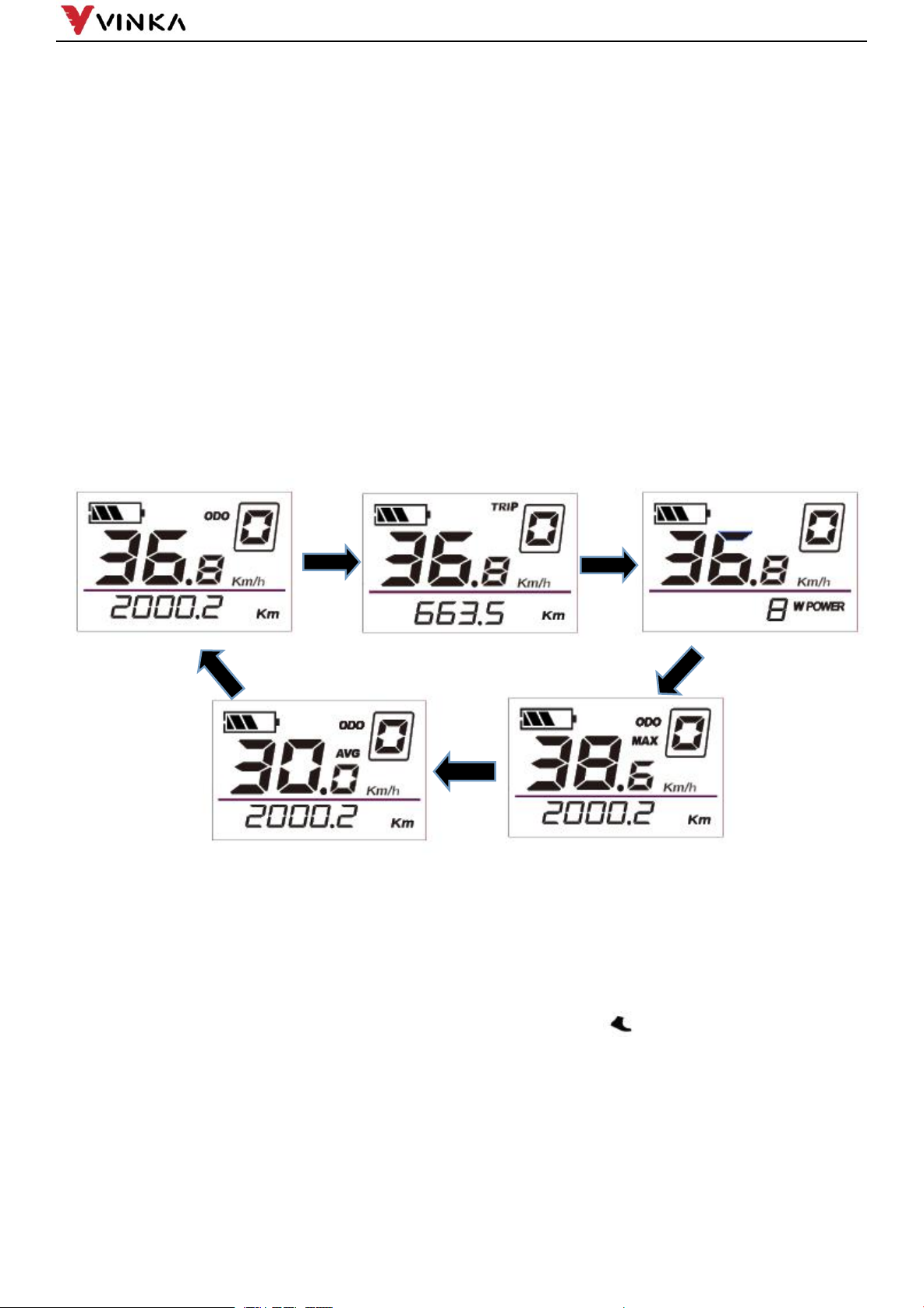
◆Display interface................................................................................................................................................. 3
◆Push-assistance ................................................................................................................................................ 3
◆Switch lighting ON/OFF..................................................................................................................................... 4
◆Assist level selection.......................................................................................................................................... 4
◆Battery indicator.................................................................................................................................................. 5
◆Error code indication.......................................................................................................................................... 5
General Settings..................................................................................................................................................... 5
◆Wheel diameter setting...................................................................................................................................... 5
◆Controller software version............................................................................................................................... 6
◆Display software version....................................................................................................................................6
◆Unit exchange..................................................................................................................................................... 6
◆Brightness ..........................................................................................................................................................7
◆Maximum speed limits....................................................................................................................................... 7
◆Push assistant speed settings ......................................................................................................................... 7
◆TRIP clear function............................................................................................................................................. 8
◆Exit settings......................................................................................................................................................... 8
Quality assurance and warranty scope............................................................................................................... 8
Connection layout................................................................................................................................................... 9
Warnings.................................................................................................................................................................. 9
Attached list 1:Error code definitions................................................................................................................ 10
Attached list 2:Functions corresponding to instrument characters.............................................................. 11

1
Product name and model
E-bike Intelligent LCD
Model: DR23
Specifications
●36V/48V Power Supply
●Rated working current: 10mA
●The maximum working current: 30mA
●Off-state leakage current: <1μA
●Working temperature:-20°C~ 60°C
●Storage temperature: -30°C~ 70°C
Appearance and Size
Product appearance and dimensional drawing (unit: mm)
*Display side is cable free.
Function and Button Definition
◆Function Summary
DR23 has many functions to meet riders’ needs. The indication elements are as follows:
●Intelligent battery SOC indication
●Motor output power indication
●Assist level selection and indication
●Speed indication (incl. current speed, Max. speed and Avg. speed)
●ODO and Trip
●Push-assistance function and indication
●Trip time indication
●Backlight ON/OFF and indication
●Error code indication

2
●Various Parameters Settings (e.g. wheel diameter, speed limit, battery power bar, assist level, current limit,
password enable, etc.)
●Recover Default Settings
◆Function layout
◆Button Definition
There are three buttons (
, ,
) on DR23 display. In this manual, we use words
ON/OFF, UP, DOWN to represent these 3 symbols ( , , ).
Installation
DR23 can be mounted on the left side of handlebar close to its grip. Adjust the angle for a good screen view.
Cut off the power before connecting the corresponding connectors between display and controller.
General Operation
+/light button
On/Off button
-/push assist

3
◆Switching the E-bike System mode ON/OFF
To switch on the E-bike system and provide the power supply to the controller, hold the On/Off button for 1s.
To switch off E-bike system, hold the On/Off button for 1s. The E-bike system no longer uses the
battery power.
When E-bike system is switched off, the leakage current is less than 1 μA.
■When the E-bike is parked for over 15 minutes, the E-bike system switches off automatically.
◆Display Interface
After switching on the E-bike system, the display shows Current Speed and ODO(total distance) by default.
Press the ON/OFF button to switch between indication functions below:
ODO (Km)→ Trip (Km) → Motor Power (W)→ODO (Km)→ Max. Speed (Km/h)→ Avg. Speed (Km/h) , it
cycles back to ODO km again.
Display indication cycle interface
◆Push-assistance
To activate the push-assistance function, press and hold the DOWN button. After 1 seconds, E-bike is
activated to go at a uniform speed of 6 Km/h while the screen displays “& P ”.
The push-assistance function will be switched off as soon as you release the DOWN button and ebike gets
back to the status before the push assistance is engaged.

4
Push-assistance mode
■The power-assisted push function can only be used when the user pushes the electric vehicle,
please do not use it in the riding state
◆Switching Lighting ON/OFF
Long press the UP button for more than 1 second to turn on the headlights, the instrument display shows
the headlight symbol, and the brightness of the display backlight decreases.
Press and hold the UP button here for more than 1 second to turn off the headlights, the headlight symbol
on the instrument display disappears, and the backlight brightness is restored.
Switching Lighting on/off
◆Assist Level Selection
The assist level of the E-bike drive can be changed anytime, even during riding.
The assist level ranges from 0 to 5 (level 0 to level 5). The default assist level is “1” when the display is
started. The output power is zero on Level “0”. Level “1” is the minimum output power. Level “5” is the maximum
output power.
Press UP/DOWN button to switch between the E-bike system assist levels and change the motor output
power.
Assist Level “3”

5
◆Battery Indicator
The five battery power bars represent the capacity of the battery. The five battery bars are bright when
the battery is in full voltage. When the battery is in low voltage, battery frame will flash at the frequency
of 1HZ to give a notice that the battery needs to be recharged immediately
Flash (low voltage)
Battery
Indicator
◆Error Code Indication
The components of the E-bike system are continuously and automatically monitored.
When an error is detected, the respective error code is indicated in text indication area.
Refer to detailed definition of the error codes in Attached list 1.
Error Code Indication
■Have the display inspected and repaired when an error code appears. Or else, you will not be able to
ride the bike normally. Please always refer to an authorized bicycle dealer.
General Settings
◆Wheel diameter settings
d1A refers to wheel size settings. Settable values are 12,14,16,18,20,22,24,26, 700C,28,29. Press UP/DOWN
to choose the correct wheel size to ensure the correctness of speed and mileage indication. The default value is
20 inch. Press on/off button to access speed limit setting interface.
Wheel diameter settings

6
◆Controller software version
CLS refers to controller software version number. The version number is reported by the controller. It can
not be adjusted from display side
Controller version number reading interface
◆display software version
DPS refers to display software version number. The display software version is not adjustable. It is decided
by the software.
Display software version interface
◆unit exchange
U refers to unit. 1 is metric and 0 is imperial. Press UP/DOWN to change the unit for speed and mileage. Press
on/off button to confirm. The default unit is metric( km/h and km)
Unit exchange interface

7
◆Brightness
bLG refers to Backlight level settings. The settable range is 1 2 3 4 5. 1 is the darkest, 3 is standard and 5 is the
brightest. The default value is decided by the controller when the display leaves factory. Press UP/DOWN to change
the brightness levels. Hold the on/off button to confirm and exit the settings.
Backlight settings
◆Maximum speed limits
SPd refers to top speed limit settings, the settable range is 5 to 46 km/h. The top speed on
the display is reported by the controller. Press UP/DOWN to increase or decrease the numbers to
your desired value.Hold the ON/OFF buttons 1 seconds to confirm and exit the settings.
Speed limit settings
◆Push assistant speed settings
PSH refers to push assistant speed settings. The settable range is 3km/h to 6km/h. Press
UP/DOWN to increase or decrease the speed limit to your desired value. Hold the on/off button
1s to confirm and exit the settings status.
Push assistant speed settings

8
◆TRIP clear function
In TRIP mode and Trip is not 0, press the UP and DOWN buttons at the same time for more than 1 second
to clear the trip data information.
◆Exit settings
In personalized parameter settings interface,
Short press the ON/OFF button is to confirm the input.
Hold the ON/OFF button is to store the settings and exit the current setting.
Quality assurance and warranty scope
ⅠWarranty
1) The warranty will be valid only for products used in normal usage and conditions.
2) The warranty is valid for 24 months after the shipment or delivery to the customer.
ⅡOthers
The following cases do not belong to warranty scope:
1) The display is demolished.
2) The damage of the display is caused by wrong installation or operation.
3) The shell of the display is broken after the display is out of the factory.
4) The cable of the display is broken.
5) Beyond warranty period.
6) The fault or damage of the display is caused by the force majeure (e.g., fire, earthquake, etc.)
◆Connection Layout
①Socket type male connector( display is cable free)

9
Wire sequence table
Wire serial
Code
Function
1
BAT
Battery power wire
2
GND
Ground wire
3
DTX
Data transmission wire of the display
4
DRX
Data receiving wire of the display
5
ON-OFF
Controller power control wire
6
Walk
Push control wire
■displays have wire connection with water-proof connectors, users can not see the pin
wire colors.
②Outlet diagram that comes with the display
Warnings:
1. Use the display with caution. Don’t attempt to release or link the connector when battery is power on.
2. Try to avoid hitting the display.
3. Don’t modify system parameters to avoid parameter disorder.
`
4. Make the display repaired when error code appears.
■This manual instruction is a universal version for VINKA DR23 display. Software specific, versions of this
display may be different. Please always refer to an actual version.

10
Attached list 1: Error code definition
Error code
Definition
90
Torque Zero Error
11
Torque Out Range
92
Torque Sensor Fault
13
Gear Sensor Error
15
Speed Sensor Error
18
Cadence Error
20
PCB Over-Temp Warning
A1
PCB Over-Temp Error
22
PCB Sensor Fault
25
Motor Over-Temp Warning
A6
Motor Over-Temp Error
A7
Flash Error
80
Communication Lost
32
LORA Communication Lost
01
Communication CRC Error
40
Motor EST Error
41
Motor Over-Peak Current
C2
Motor Loss Phase
43
Motor Over DC Current
D0
Battery Over Voltage
51
Battery Low Voltage
52
Battery Over Current
E0
Battery Version Error
E5
Display Version Error

11
Attached list 2:Functions corresponding to instrument characters
NO.
Symbol
Definition
1
Wheel diameter
2
Controller software version
3
Display software version
4
Unit exchange
5
Backlight level
6
Speed limit
7
Push assistant speed
Table of contents
Other VINKA Bicycle Accessories manuals