FitDesk 4020 User manual

IMPORTANT: READ THE OWNER’S MANUAL BEFORE ASSEMBLING
1161 SOUTH PARK DRIVE, KERNERSVILLE NC 27284
DISTRIBUTED BY FD PRODUCTS LLC.
VISIT OUR WEBSITE: WWW.THEFITDESK.COM
OR CALL US AT 1-855-713-8887 MONDAY - FRIDAY 9 A.M. - 5 P.M. EST
Standing Bike Desk Owner’s Manual
Model: 4020
R

TABLE OF CONTENTS
Introduction.............................................................1
Safety Warnings.....................................................2
Customer Support..................................................3
Tools / Hardware / Knobs / Bracket........................4
Parts / Components................................................5
Assembly................................................................6
Warnings and Labels...,,,,,,,,,,,,,,,,,,,........................9
Operational Instructions..........................................9 Optional Products.................................................17
Operational Instructions.......................................10
Set-Up / Storage..................................................10
Warming Up.........................................................11
Maintenance and Troubleshooting......................12
Warranty..............................................................13
Parts List..............................................................15
Exploded View.....................................................16
Left Pedal
Back
Cushion Back
Support
Seat
Handle
Bars
Frame
Rear Stabilizer
Front Stabilizer
Right Pedal
Flywheel
Cover
Tension Control Knob
Weight of Bike: 40 lbs (18.2 kgs)
Recommended User Height Range
5.0" to 6'5" (152 cm to 199 cm)
Recommended Max User Weight
242 lbs (110 kgs)
Foot Print in OPEN position
24.5" wide x 36.5" long x 45" high
INTRODUCTION
Thank you for choosing FitDesk® We hope
your new FitDesk® Recumbent Bike becomes
a regular part of your daily routine and we wish
you good health and increased wellness as
you use the FitDesk® to infuse activity into
parts of your day.
Before you start assembling your new
FitDesk® please take a moment to read this
manual carefully.
1
R

SAFETY WARNINGS - URGENT PLEASE READ THIS SECTION
1. Read the entire manual before assembling and using the equipment. Safe use can only be achieved if the equipment
is assembled, maintained and used properly. All users of the equipment must be informed of all warnings and precautions.
2. Before starting or using this equipment you should consult your doctor to determine if you have any health conditions
that could create a risk to your health and safety, or prevent you from using the equipment properly.
3. Be aware of your body's signals. Incorrect or excessive exercise can damage your health. Stop exercising if you
experience any of the following symptoms: Pain, tightness in you chest, irregular heartbeat, extreme shortness of
breath, feeling light headed, dizzy or nauseous. If you do experience any of these conditions consult your physician.
5. Before transporting. Fold frame in closed position with support pin engaged to prevent opening. Use transport wheels
when possible. The frame must be in the closed and locked position prior to transport.
6. Read and follow all warning stickers on the FitDesk®.
7. Warm-up stretching is recommended before exercise.
8. Mount and dismount carefully. - Extreme movements CAN TIP MACHINE - INJURY AND EQUIPMENT DAMAGE CAN
OCCUR.
4. Keep pets and young children away from the equipment.
9. Use the equipment on a solid, level surface with a protective cover for your floor or carpet. The equipment should
have at least one yard of free space all around it.
WE WANT YOUTO SAFELY USE THIS PRODUCT
10. Inspect and tighten all parts often. Replace any worn parts immediately.
11. If you find any defective components while assembling or checking the equipment, or if you hear any unusual noises
coming from the equipment during use, stop immediately. Do not use the equipment until the problem has been resolved.
12. Recommended maximum user weight of 242 lbs, 110 kgs. Recommended for ages 13+
The equipment is suitable for home and office use only. Do not use in commercial or rental settings. This item was
not intended or designed for use in commercial or public places.
13. Do not stand while pedaling. For light exercise use only.
14. Seat Comfort- Consult a physician if you feel pain for excessive discomfort while on the seat.
2

3
NEED HELP?
CONTACT US FIRST
1-855-713-8887
CUSTOMER SERVICE QUESTIONS
WWW.THEFITDESK.COM
FOR FASTEST POSSIBLE SERVICE PLEASE HAVE AVAILABLE
Model # (4020) - Serial # (located on tubular base safety sticker)
Step 1: www.thefitdesk.com
Step 2: “Support”
Step 3: “Submit A Support Ticket”
EASY TO USE CUSTOMER TICKETING
MONDAY - FRIDAY 9 A.M. - 5 P.M. EST
NOTE: If Parts or hardware are missing contact customer service immediately.
Please do not discard your packaging until your entire FitDesk®is fully assembled. Some parts are
purposely packaged in cardboard or Styrofoam and can mistakenly be thrown away with the packaging.
Note: Do not over tighten knobs it can cause stripping of threads.
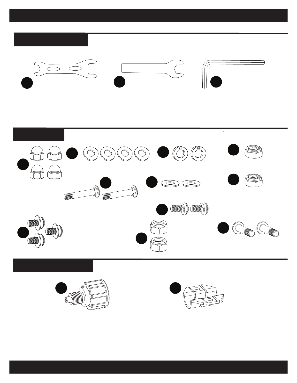
HARDWARE
KNOBS & BRACKETS
Each FitDesk®comes equiped with one Allen Wrench (BB1) and Wrenches (AA1) (AA2). .
It is recommended if you have your own tools, that you use a 1/2” socket with drive and a 15 mm
Wrench to tighten the pedals from time to time.
DD.
BB. (4) Stabilizer Washers CC. (2) Lock Washers
4
BB
EE. (2) Carriage Bolt (M8 x 45.5mm)
(4) Cap Nuts EE
FF. (2) Flat Washers
KK. (2) Back Cushion Allen
Bolt (M8 x 42mm)
II. (3) Oval Head Screw
(M8 x 16mm) w Washer
HH. (2) Oval Head Screw
(M8 x 16mm)
JJ. (2) Nylon
Lock Nuts
(M8)
II
HH
JJ
KK
AA
CC
FF
Note: Hardware and Tools not shown to actual size.
LL. (1) Adjustment Knob
(Pre-Assembled on Frame)
LL MM
TOOLS (SUPPLIED)
AA2 AA2 Wrench BB1 BB1 Allen Wrench
AA1 AA1 Wrench
Estimated Assembly Time : 20 minutes
MM.(1) Adjustment Bracket
(Pre-Assembled on Frame)
DD. (1) Right Pedal Nut
DD
GG.
(1) Left Pedal Nut
GG

E. Saddle
Back
Post
H. Seat
Support
Tube
B.Seat
Back
D.Seat
PARTS / COMPONENTS
5
C.Handle Bars
C
A1 / A2. Left and Right Pedals
A2A1
G.Front Stabilizer
G
I. Rear Stabilizer
I
I
H
E
F. Main
Frame
F
B
D

6
ASSEMBLY
We take great care to deliver quality products that will last for years. However, even with years of
manufacturing experience and high levels of quality control, problems still occur from time to time.
If you experience a problem with any part of your new FitDesk®, please contact us before returning
your product. In most cases, we can quickly solve your issue with technical advice or easily send you
a replacement part if needed.
NOTE: Before assembly please check all parts carefully.
The included Screwdriver Allen Wrench (AA) and
Wrenches (BB1) (BB2) are required to complete
this assembly. To make the assembly easier, we
recommend using a 1/2” inch Socket,15mm
Wrench or a Number five Allen Wrench.
15mm Wrench
1/2” Socket
Wrench
Number five Allen
Wrench
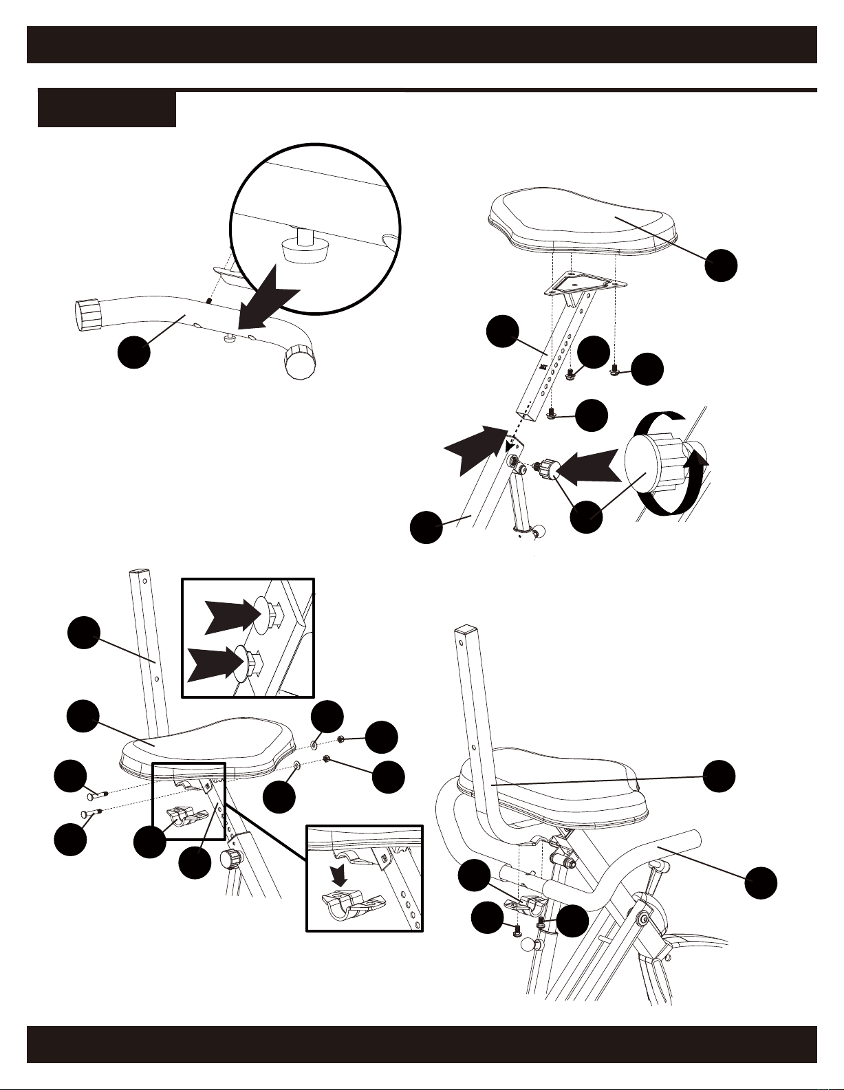
Step 1: Turn the Frame Locking Knob on the
Main Frame (F) to loosen it, then pull it out to
unfold the Frame.
Frame
Locking
Knob
Note: Check Base Stabilizers for tightness periodically.
FRONT
REAR
Before assembly of Rear (I) and Front Stabilizer (G) remove the four Stabilizer Washer (BB) and the four Cap Nuts (AA).
Step 2: After removal, attach the Rear (I) and the Front Stabilizers (H) (Figure 3) to the Main Frame (F) using
Stabilizer Washers (BB) and four Cap Nuts (AA ).Tighten with Wrench (BB2). Figure 2 and 3
F
AA
BB
AA
BB AA
AA
AA
BB
I
G
FIGURE 1
FIGURE 2 FIGURE 3
Note: Please make sure the Front Stabilizer
(G) with wheels is assembled facing the front
of the product, for later ease of storage.
ASSEMBLY
7
Step 7: Turn the Seat Adjustment Knob (LL) on the Main
Frame (F) to loosen it, then pull it out to adjust seat
height. Figure 7
Step 6: Slide the Seat Support Tube (H)
into the Main Frame (F) after assembly.
Step 4: Adjust the knob
on the bottom of the Rear
Stabilizer (I) from the floor
around 2 to 3 mm
or until bike is level.
Figure 4
FIGURE 4
FIGURE 7
FIGURE 5
DETAIL
FIGURE 8
FIGURE 9
FIGURE 6
Step 5: Assemble the Seat (D) to the Seat Support
Tube (H). Using attached Wrench (AA1) tighted the
three Oval Head Screws (M8 x 16mm) (II), Figure 5
Step 9: Fasten Handle Bars (C) to the
Saddle Back Post (E) with two Oval Allen
Screws M8 x 16mm (HH) and Handlebar
Bracket (MM) tIghten with the attached Allen
Wrench (BB1). Figure 9
DETAIL
DETAIL
D
F
H
B
H
E
E
C
I
LL
II
JJ
FF
FF
EE
EE
JJ
II
II
Note: Be sure
the bolts sit
flush in the
square holes.
DETAIL
HH
HH
Note: You do not have to remove the Knob to
adjust the height. Loosen the Knob and pull,
then retighten when the desired height is reached.
MM
Step 8: Install the Seat Back Post
(E) to the Seat Support Tube (H)
with the Carriage Bolts (M8 x 45.5m)
(EE), Washers (FF) and M8 Nylon Lock Nuts (JJ)
Tighten with the attached Wrench (AA1).
Remove Handlebar Bracket (MM) (Detail) Figure 8
MM

ASSEMBLY
8
C
Step 10: Install the Seat Back Cushion (B) to
the Saddle Back Post (E) using two Oval Head
Allen Screws M8 x 42mm (KK), Lock Washers
(CC) tighten using the supplied Allen Wrench
(BB1). Be sure the Allen Bolts (KK) and Lock
Washers (CC) sit flush in the holes. Figure 10
FIGURE 10
E
KK
KK
CC
CC
B
F F
Step 11: Using the supplied Wrenches (AA1) (AA2) attach the Left Pedal (A1) to the crank arm by tightening
the pedal and holding the back nut at the same time. (Left Pedal is reverse thread) Figure 11
Step 12: The Right Pedal (A2) is installed the same way using the supplied wrenches. (Right pedal is not
reverse thread) (AA1) (AA2). Figure 12
WARNING: Make sure the pedals are threaded properly to ensure you do not damage the threads.
Note: The Pedals must be made extra tight.
Use the included Wrenches or a 15mm wrench to finish tightening.
Note: Left
Pedal Is
Reverse
Thread.
Note: Right Pedal Is
Not Reverse Thread.
AA1 AA1 DD
AA2
GG A1
FIGURE 12FIGURE 11
A2

WARNINGS AND LABELS
NOTE: Read all warning stickers
before operating this product.
R
L
9
25OLBS/113 KG
4020
L
R
OPERATIONAL INSTRUCTIONS NOTE: Before operating please read carefully
RESISTANCE KNOB
Push down knob from 1-8 to change
resistance. To increase the load, push
the the knob located on the main frame
down. To decrease the load turn the
tension knob up.

SET UP / STORAGE
10
This model 4020 FitDesk®uses a quick release frame unlock design.
As a safety precaution please use the technique shown here when opening and closing frame.
STORAGE
Pull pin on frame support while placing foot on base. Open Main Frame (I) then release pin, then pull desk toward
you. Figure 1 and 2
Figure 2. TO CLOSE:
FIGURE 1
OPEN
B
FIGURE 1 OPEN
Note: Before transporting. Fold frame in closed position with support pin engaged to prevent
opening. Tighten desk knobs. Use transport wheels when possible. The frame must be in the
closed and locked position prior to transport.
Place Feet As Marked
FIGURE 2 CLOSE
DETAIL LOOSEN
Note: You do not have to remove the Knob to adjust the height.
Loosen the Knob and pull, then retighten when the desired height
is reached.
SEAT HEIGHT ADJUSTMENT
This model bike has nine levels of seal height adjustment.
Pull out knob and move the seat post up or down to your
desired height and then tighten the knob.
OPERATIONAL INSTRUCTIONS
WARMING UP
11
Before you use the FitDesk®, it is advisable to warm up and stretch your muscles. Simple warm up
exercises and stretches can help you be more efficient and safer during your time on the FitDesk® .
STRETCHING
Hold each stretch 10 to 30 seconds. If you feel you need more, stretch the other side and return for
another set of stretching.
• The stretch should be strong, but not painful.
• Do not bounce.
• Breathe while you’re stretching. Exhale as you stretch, inhale while holding the stretch.
SUGGESTED BASIC STRETCHING EXERCISES
COOL DOWN
It is good to also stretch after using the FitDesk®when you’re cooling down because your limbs,
muscles and joints are still warm. Stretching can help reduce the buildup of lactic acid, which can
lead to muscles cramping and stiffness.
WARNING: Always check with your physician before
starting any type of exercise program.
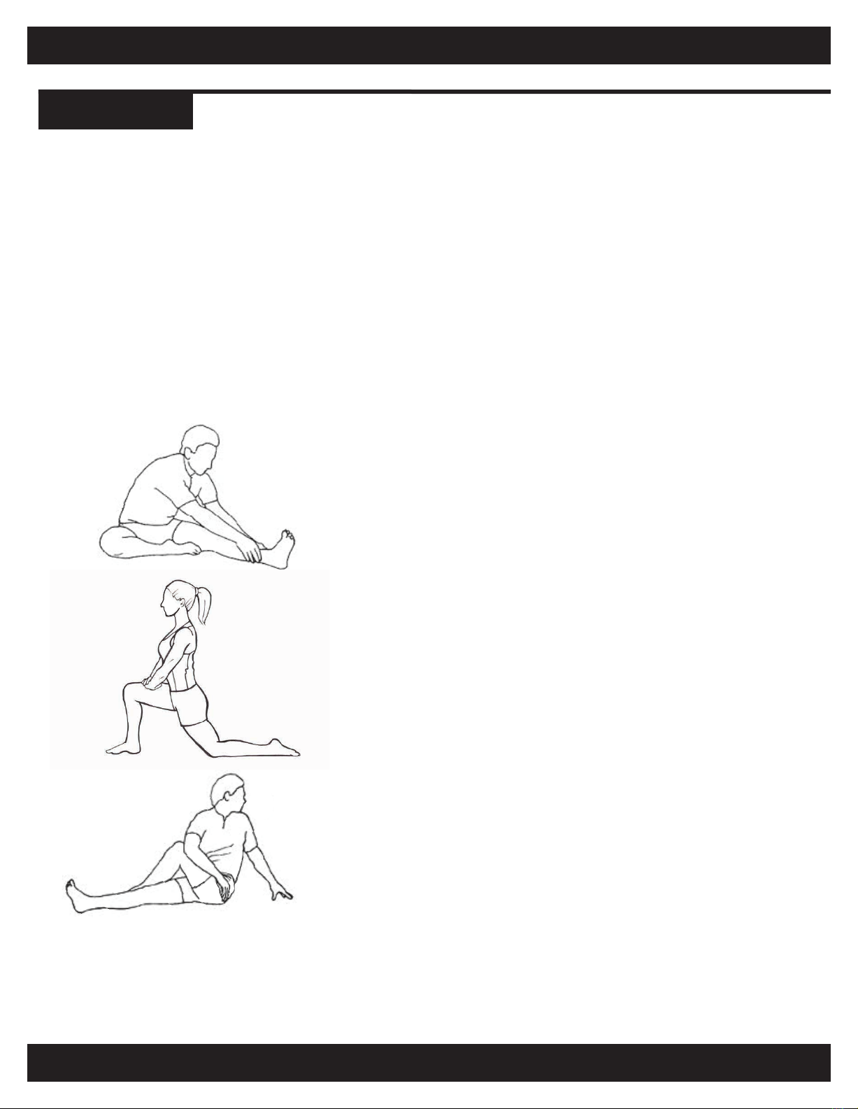
SEATED STRETCH
Sit with both legs straight. Bend your left knee and cross it
over your right leg so that your left ankle ends up by your
right knee. Now twist your torso so that your right elbow
ends up docking on your left knee. You can put some
pressure from your elbow on your knee to push it in towards
the midline of your body to increase the intensity of the
stretch. Hold for 15-30 seconds and switch sides.
SEATED HAMSTRING STRETCH
Sit on the floor, a step or on a chair with one leg stretched
out in front of you, the other bent. Sit up tall and then lean
forward as far as you comfortably can, stretching the back
of the leg. You can grab onto the thigh, calf, ankle or foot to
pull you further into the stretch. Hold for 15-30 seconds and
switch sides.
HIP FLEXOR LUNGE STRETCH
Get into a lunge position on the floor, right foot forward and
left knee back, both knees at about 90 degrees. Keeping
the torso straight and abs engaged, lunge forward, gently
pressing until you feel a stretch in the front of the hip. You
can also squeeze the glutes for a deeper stretch. Hold for
15-30 seconds and switch sides.

MAINTENANCE AND TROUBLESHOOTING
12
HARDWARE
Verify that all bolts are present and properly tightened.
TIP: Inspect nuts, screws and knobs on a weekly basis.
FRAME, SEAT, SEAT MOUNT
Properly adjust seat back for comfort and stability.
NOTE: Check frame, seat, seat mount for wear.
WARNING: Do not use if any sign of frame cracking. Worn or damaged parts and components
must be replaced immediately.
PEDALS
Check pedal (A1), (A2) tightness with 15mm wrench WHEN NEW - THEN AFTER 30 miles.
NOTE: Make Pedals EXTRA Tight during Assembly.
BASE STABILIZERS
Check Base Stabilizers bolts for tightness periodically.
The integrity of the FitDesk® bike can only be maintained when it is regularly maintained for damage
and wear. Special attention should be given to the following:

WARRANTY
13
This limited warranty is applicable to each original end-customer (hereinafter “Customer”) purchasing the FitDesk®
Model: 4020 Standing Bike Desk consisting of the structural metal frame (hereinafter the “Structural Frame”) and
various other non-frame components (hereinafter the “Non-Frame Parts”) sold by FD Products, LLC (hereinafter
“Company”) for Customer’s own use and not for resale. The Structural Frame and Non-Frame Parts are collectively
referred to herein as the “Products”.
1. LIMITED WARRANTY; EXCLUSIVE REMEDIES:
1.1. LIMITED WARRANTY ON PRODUCTS: Company warrants solely to the original Customer that (a) the
Structural Frame will be free from defects in materials and workmanship under normal use for a period of ONE (1)
YEAR from the date of original retail purchase, and (b) the Non-Frame Parts, will be free from defects in materials and
workmanship under normal use for a period of NINETY (90) DAYS from the date of original retail purchase. Notwith-
standing the foregoing, the colors and finishes of the Products may vary within a reasonable scope due to unavoid-
able color variations in different production batches, and such variations shall not constitute a material defect. This
limited warranty is limited solely to the original Customer with proof of purchase and is not transferable.
1.2. THE WARRANTY: During a covered Product’s limited warranty period, Company will, at Company’s sole
option and discretion, (1) repair the defective component or product without charge or (2) replace the defective
component or product without charge.
1.3. The foregoing limited warranty is subject to the Customer’s proper storage, transportation, handling and use
of the Products as the same are defined within Company’s then-current published guides and instructions for use
and care. The limited warranty does not include defects due to normal wear and tear, abuse or misuse, mishandling,
neglect, accident, fire, lightning, sunlight or other natural hazard, delivery or transportation damage, failure to follow
applicable directions or instructions, or improper or inadequate cleaning, maintenance, care, repairs, modifications,
or use beyond a Product’s intended use.
1.4. LIMITED WARRANTY CLAIMS PROCEDURE: To obtain performance under this limited warranty, Customer
shall notify Company in writing (to FD Products, LLC, 1161 South Park Drive, Kernersville, NC 27284, Attn: Customer
Service / Warranty Department), by email (to [email protected]), or by telephone (to (336) 423-5029)
with a full description of the defect that is covered by warranty and a copy of the dated proof of purchase of the
applicable product.
• Company shall review each such claim and issue Customer a return merchandise authorization (“RMA”) in
the event that the described defect or condition merits warranty review as determined by Company. Customers who
have been issued a RMA shall, at Company’s election, return the covered item to the same physical address listed
above for reporting initial claims. Company shall not accept any returned product without a RMA.
• Upon receipt, Company will evaluate the returned product(s) to determine if there is a warranty claim and, if
so, how Company wishes to remedy the same. During a covered product’s respective limited warranty period,
Company will, at Company’s sole and absolute option and discretion, (1) repair the defective component or product
without charge or (2) replace the defective component or product without charge. Refunds are not available
pursuant to this limited warranty.
• Customer is solely responsible for transportation of the covered product(s) to the Company for evaluation
(if applicable and requested by Company). In the event that Company determines that a claim under this limited
warranty is justified, Company shall be responsible for transportation of the repaired, corrected, replaced or
exchanged product back to Customer. Customer shall be solely responsible for the transportation of any product
back to Customer if Company determines that a claim under this warranty is not justified.
• Any repaired, corrected, replaced or exchanged Products shall be subject to the Limited Warranty set forth to
the duration of the original limited warranty period as set forth in Section 1.1. and not for any extended duration,
following their repair, correction, replacement or exchange.

WARRANTY
14
1.1. IF A COMPANY PRODUCT DOES NOT CONFORM TO THESE LIMITED WARRANTIES, THE PURCHASER’S
SOLE AND EXCLUSIVE REMEDY IS, AT COMPANY’S SOLE AND EXCLUSIVE OPTION, THE (1) REPAIR OF ANY
DEFECTIVE PRODUCT OR COMPONENT PART OR (2) REPLACEMENT OF ANY DEFECTIVE PRODUCT OR
COMPONENT PART. THE LIMITED WARRANTY AND REMEDIES SET FORTH ABOVE ARE EXCLUSIVE AND MADE IN
LIEU OF ALL OTHER WARRANTIES, REMEDIES, RIGHTS OR CONDITIONS, WHETHER ORAL OR WRITTEN,
EXPRESS OR IMPLIED, EITHER IN FACT OR BY OPERATION OF LAW, STATUTORY OR OTHERWISE, INCLUDING
THE IMPLIED WARRANTIES OF MERCHANTABILITY AND FITNESS FOR A PARTICULAR PURPOSE. COMPANY
SPECIFICALLY DISCLAIMS, WITHOUT LIMITATION, ANY AND ALL OTHER WARRANTIES, EXPRESS OR IMPLIED, OF
ANY KIND. IF COMPANY CANNOT LAWFULLY DISCLAIM IMPLIED WARRANTIES UNDER THIS LIMITED WARRANTY,
ALL SUCH WARRANTIES, INCLUDING THE IMPLIED WARRANTIES OF MERCHANTABILITY AND FITNESS FOR A
PARTICULAR PURPOSE, ARE LIMITED IN DURATION TO THE DURATION OF THIS LIMITED WARRANTY. The
Company does not assume or authorize any person to assume for them any other liability in connection with the
Products.
2. EXCLUSION AND LIMITATION OF LIABILITY:
IN NO EVENT, WHETHER BASED ON CONTRACT OR TORT OR OTHER LEGAL THEORY, SHALL COMPANY BE
LIABLE FOR ANY INDIRECT, INCIDENTAL, PUNITIVE, SPECIAL OR CONSEQUENTIAL DAMAGES, INCLUDING BUT
NOT LIMITED TO, DAMAGES TO OTHER PROPERTY, INCONVENIENCE, DAMAGES FOR LOSS OF PROFITS,
REVENUE, GOODWILL OR USE, INCURRED BY CUSTOMER OR ANY THIRD PARTY, WHETHER IN AN ACTION IN
CONTRACT, TORT, STRICT LIABILITY, OR IMPOSED BY STATUTE, OR OTHERWISE, EVEN IF ADVISED OF THE
POSSIBILITY OF SUCH DAMAGES. Some states do not allow the exclusion or limitation of incidental or consequen-
tial damages or exclusions or limitations on the duration of implied warranties or conditions, so the above limitations
or exclusions may not apply to Customer. In jurisdictions that limit the scope of or preclude limitations or exclusion
of remedies or damages, or of liability, such as liability for gross negligence or willful misconduct or do not allow
implied warranties to be excluded, the limitation or exclusion of warranties, remedies, damages or liability set forth
above are intended to apply to the maximum extent permitted by applicable law. This limited warranty gives the
Customer specific legal rights, and the Customer may also have other rights that vary by state, country or other
jurisdiction.
3. SEVERABILITY:
If any provision of this limited warranty is held to be illegal, invalid or otherwise unenforceable, such provision will
be enforced to the extent possible consistent with its stated intention, or, if incapable of such enforcement, will be
deemed to be severed and deleted from this limited warranty, while the remainder of the terms of this limited
warranty will continue in full force and effect.
4. DISPUTE RESOLUTION:
This FitDesk Limited Warranty shall be governed by and construed in accordance with the laws of the State of North
Carolina, without regard to its principles of conflicts of law. The parties acknowledge the exclusive jurisdiction of the
federal and state courts of the State of North Carolina. Any claims or disputes under this FitDesk Limited Warranty
shall be heard exclusively in any state or federal courts sitting in Guilford County, North Carolina, and both parties
expressly consent to the personal jurisdiction and venue of the North Carolina state and federal courts for such
actions.

19
COMPLETE PARTS LIST
REPLACEMENT PARTS
15
DESCRIPTION:
1. Seat
2. Seat Support Tube
3. Oval Head Screw (M8 x 16 mm) W/Washer
4. Seat Adjustment Knob
5. Main Frame
6. Allen Bolt (M8 x 42 mm)
7. Lock Washer
8. Saddle Back Post
9. Seat Back
10. Nylon Lock Nuts (M8)
11. Flat Washers
12. Carriage Bolt (M8 x 45.5 mm)
13. Handle Bars
14. Handlebar Bracket
15. Oval Allen Screw (M8 x 16 mm)
1
1
3
1
1
2
2
1
1
2
2
2
1
1
2
4
4
1
1
1
1
1
1
1
1
1
1
16. Cap Nut
17. Stabilizer Washer
18. Pedal (Right)
18. Pedal (Left)
19. Pedal Nut (Right)
20. Front Stabilizer
21. Rear Stabilizer
A1 Pedal Left 9/16”
A2 Pedal Right 9/16”
AA1 Wrench
AA2 Wrench
QTY:
DESCRIPTION: QTY:
F Main Frame
1
1
Crank Arm Left
Crank Arm Right
1
BB1 Allen Wrench
1
19. Pedal Nut (Left)
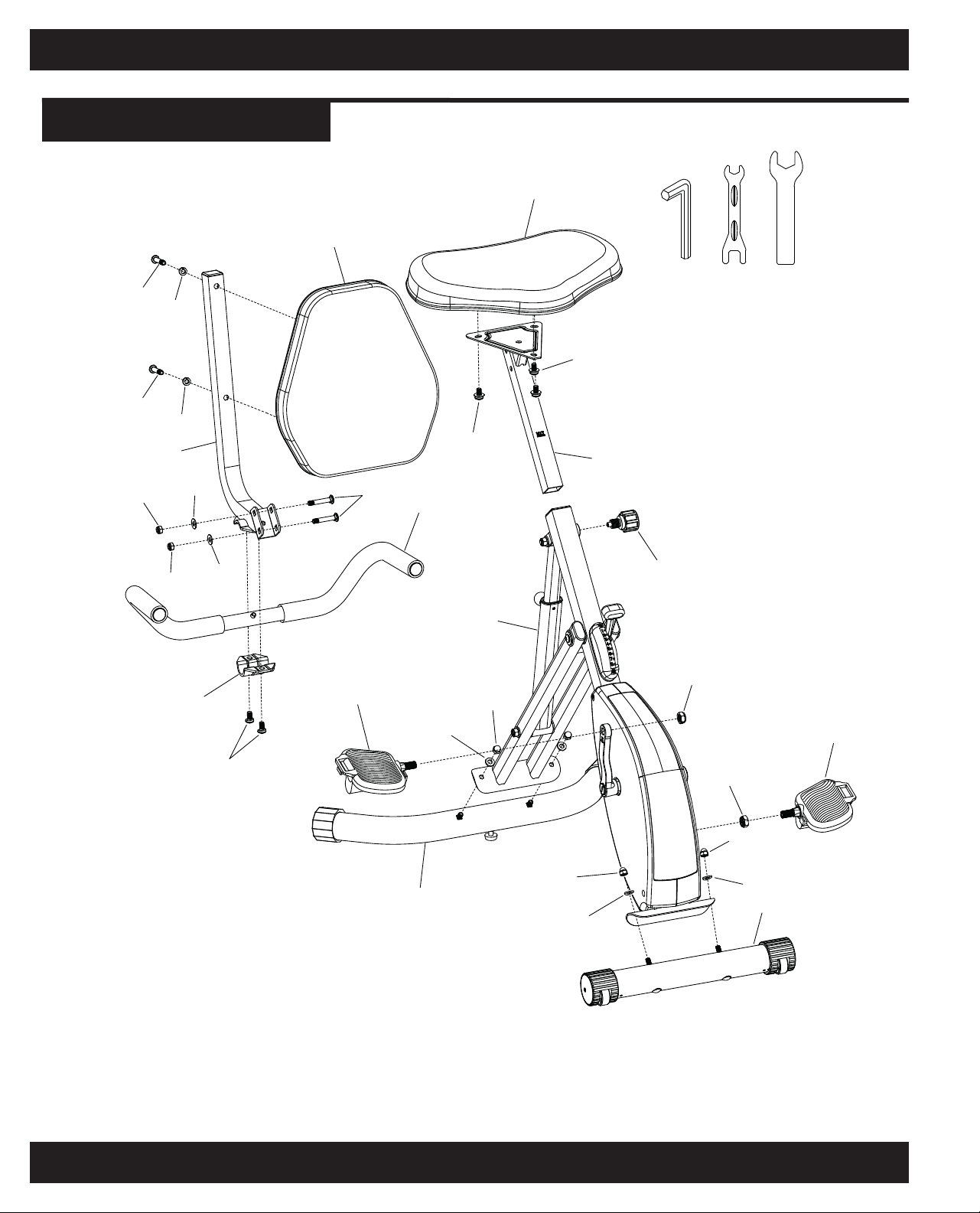
COMPLETE PARTS LIST
16
For Questions or Replacement Parts Contact:
1-855-713-8887
MONDAY - FRIDAY 9 A.M. - 5 P.M. EST
67
67
8
10 11
10 11
9
12 13
1
3
3
2
4
5
14
15
18 R
21 16
17
17
16
16
17
20
19 L
18 L
19 R
ABC

17
FitDesk®Model: 3.0
FitDesk®Model: 2050
THE ORIGINAL
OPTIONAL PRODUCTS
To buyother products go to our
Website @ www.thefitdesk.com
R
Sit-To-Stand Desk
Recommended
Max Load: 25 lbs. (11.3 kgs.)
Recommended User Height Range
4’10” to 6’5” (147 cm to 199 cm)
Recommended Max User Weight
300lbs (136 kgs)
Weight of Bike: 48 lbs.
Foot Print in OPEN position
16” wide x 26” long x 45” high

METER / ASSEMBLY
Completed
Meter and Holder
F
A
B
C
D
Plug Meter Wire Port (C) into
the Main Frames (A) Meter
Wire Connector (B).
E
Slide the Meter Holder (E)
onto the back slot of the Meter.
(F)Plug Meter Wire Port (D)
into the back of the Meter (F)
See the back side of this
sheet for Meter Operation
Instructions. For desktop
or counter use.
Model: 4020
METER / OPERATION
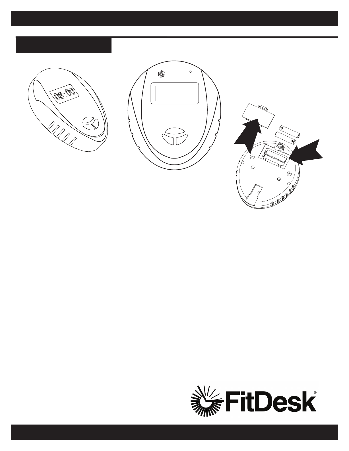
BATTERY
INSTRUCTIONS
INSTALLING AND REPLACING
FitDesk® METER BATTERIES:
The Meter (M) operates using
two AAA batteries.
Batteries are included
Refer to the illustration to install
or replace the batteries.
For Questions Contact:
1-855-713-8887
MONDAY - FRIDAY 9 A.M. - 5 P.M. EST
FitDeskR
CAL
ODO
DIST
SPEED
TIME
SCAN
MODE
SET
RESET
INSTRUCTIONS:
1. Mode button advances the Meter.
a. Time in use
b. Speed - MPH
c. Distance - Miles or KM
d. Calories burned
e. Total distance on FitDesk - ODO in Miles or KM.
®
2. Reset button allows for Meter to be reset for time.
Distance and Calories Mode.
a. Stop pedaling then push reset to reset each Mode.
3. Scan will automatically start at each Mode.
4. Set button to count down feature. Hit the Mode button
to stay on “Time” make sure you are not in Scan Mode.
Hit “Set” until the desired count down time is displayed.
a. To Stop Scan press mode button again.
b. Scan indicator is on screen when in Scan Mode.
TROUBLESHOOTING:
1. Meter will turn on as soon as you start pedaling.
2. If Meter does NOT show zero even if you push the Mode Button.
a. Check to see that batteries are fresh and properly installed.
3. If zeros display when you press the Mode Button, But not when pedaling.
a. Check connection to Meter and connection from frame to Meter.
Model: 4020
Table of contents
Other FitDesk Exercise Bike manuals


