3
SAFETY INFORMATION
For queries or additional product information, please call our Service Centre on:
087 997 0865
Please have your model name on hand.
www.everlastsa.co.za
Everlast/SA everlast_sa
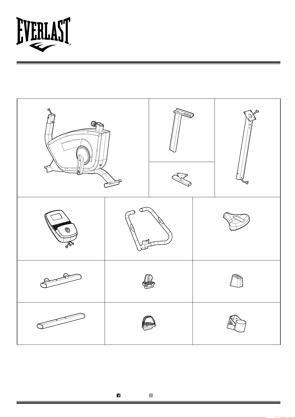
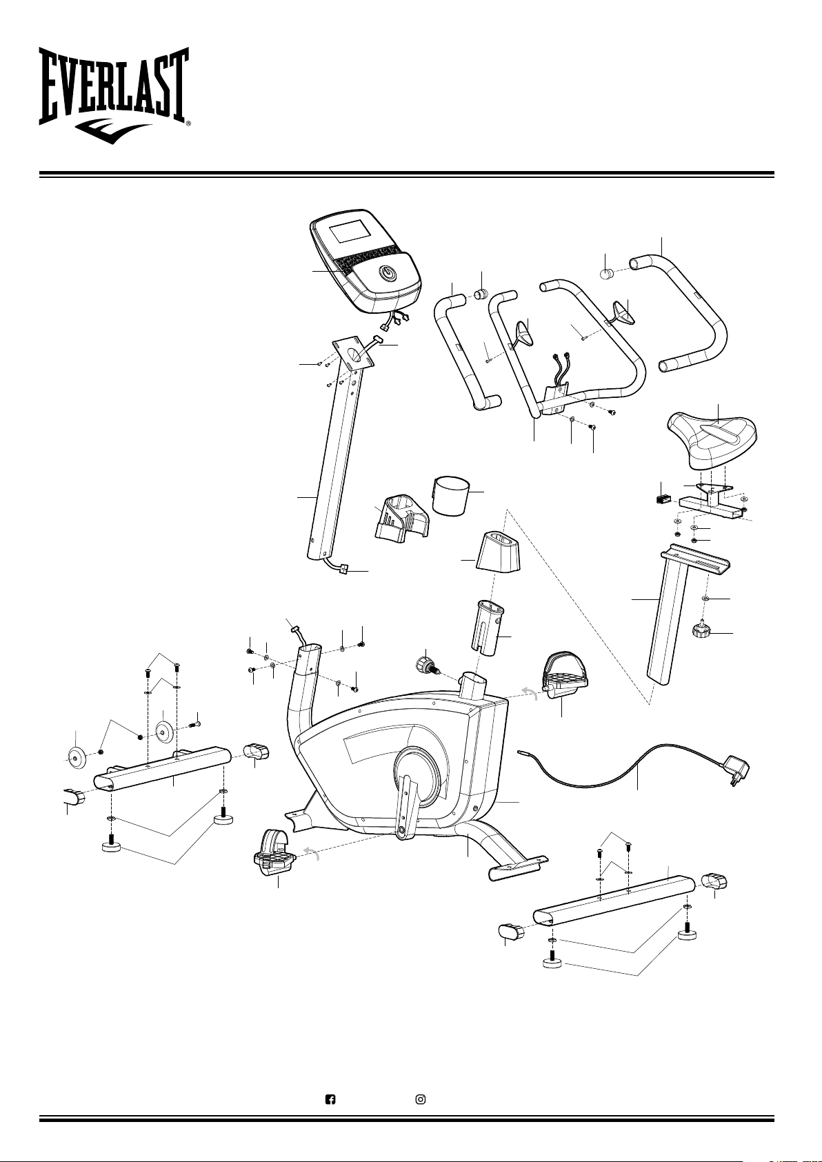
ASSEMBLY
• Check you have all the components and tools listed,
bearing in mind that for ease of assembly, some
components are pre-assembled.
• Keep children and animals away from the work area
as small parts could be choked on if swallowed.
• Make sure you have enough space to layout the
parts before starting.
• Assemble the equipment as close to its final
position (in the same room) as possible.
• Position the equipment on a clear and level surface.
• Dispose of all packaging carefully and responsibly.
USE
• It is the responsibility of the owner to ensure that
all users of this equipment are properly informed as to
how to use this equipment safely.
• This equipment is intended for domestic use only. Not
for use in any commercial, rental or institutional
setting.
• Before using the equipment to exercise, always
stretch first to properly warm up.
• If the user experiences dizziness, nausea, chest
pain or any other abnormal symptoms stop the
workout and seek immediate medical attention.
• Only one person should use the equipment at a
time.
• Keep hands away from all moving parts.
• Always wear appropriate workout clothing when
exercising. DO NOT wear loose or baggy clothing
as it may get caught in the equipment. Always wear
athletic shoes to protect your feet while exercising.
• DO NOT place any sharp objects around the
equipment.
• Disabled persons should not use the equipment
without a qualified person or doctor in attendance.
• Max user weight 120kgs.
IMPORTANT - TO REDUCE THE RISK OF SERIOUS INJURY, READ THE ENTIRE MANUAL BEFORE YOU
ASSEMBLE OR OPERATE THE EVERLAST FUSION EXERCISE BIKE. IN PARTICULAR, NOTE THE
FOLLOWING SAFETY PRECAUTIONS:
WARNING: Before beginning any exercise program, consult your physician. This is especially important
for individuals over the age of 35 or with pre-existing health problems. You MUST read all instructions before
using any fitness equipment. The manufacturer and its associates and partners take no responsibility for
personal injury or property damage sustained by or through the use of this product.
PHYSICIAN WARNING: Not all exercise equipment and training programs are suitable for everyone. It is
recommended that you consult your physician before using this equipment or beginning any training program.


 Service manual")