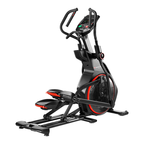
FitLux 5200 User manual

FitLux 5200
ELLIPTICAL TRAINER
Owner's Manual
Made in Taiwan

INDEX
IMPORTANT NOTICE . . . . . . . . . . . . . . . . . . . . . P. 1
ASSEMBLY PARTS LIST . . . . . . . . . . . . . . . . . . . P. 2
ASSEMBLY INSTRUCTION . . . . . . . . . . . . . . . . . . P. 3-6
COMPUTER INSTRUCTION . . . . . . . . . . . . . . . . . P. 7-17
EXPLODED DRAWING .. . . . . . . . . . . . . . . . . . . . P. 18
PARTS LIST. . . . . . . . . . . . . . . . . . . . . . . . . . . P. 19
DANGER Check that all items are complete and in
good condition.
WARNING In the assembly of the bolts, it is
recommended that one should use ones
hand in tightening the bolts prior to its
completion. Once completed remember
to have all the bolts securely fastened to
prevent accident.
ATTENTION Be sure to carefully follow all the steps in our
assembly instruction.
CAUTION:
!
!
!

1
IMPORTANT NOTICE:
THIS EQUIPMENT IS ONLY FOR HOME USE,
NOT FOR COMMERCIAL PURPOSE.
USER'S WEIGHT SHOULD BE LIMITED ONLY TO 150 KGS.
1. Before proceeding into any type of exercise program, it is
recommended that one should first consult a physician.
2. Be sure to inspect that every part of the machine that has bolts
on it are secured.
3. Do not expose to humidity as it may caused malfunction to
the equipment, any malfunction or injuries caused due to the
aforementioned we would not be held liable for this.
4. Wearing of sneakers and sport garments before initiating an
exercise program is recommended.
5. Initiate any type of exercise 40 minutes after each meal.
6. Warm up before an exercise would prevent injuries.
7. People suffering from fatigue, fever or high blood pressure
should first consult a doctor or physician prior to an exercise.
8. This exercise equipment is for ADULT use only.
9. Proper attention, guidance and supervision should be given to
some aged people, children or handicapped persons.
10. Please do not insert any foreign objects unto any part of the
machine for it would damage the unit.

2
Assembly No. Llist
ASSEMBLY PARTS LIST
1. MAIN FRAME. . . . . . . . . . . . 1
2. BOTTOM FRAME . . . . . . . . . 1
3. PEDAL SUPPORT (R+L). . . . . . 2
4. SWING HANDLEBAR (R+L) . . . . 2
5. HANDLEBAR POST . . . . . . . . 2
6. PULL ROD . . . . . . . . . . . . . 1
7. TOP JOINT COVER & SCREW . 4+8
8. COMPUTER . . . . . . . . . . . . 1
9. DECORATION COVER & SCREW
. 2+3
10.WHEEL COVER & SCREW . . . 2+4
11.JOINT COVER & SCREW . . .4+4+4
12.SPACER . . . . . . . . . . . . . . 2
13.ADAPTER . . . . . . . . . . . . . 1
10 11
12 13
2
8
1
5
4
6
7
9
3
AB C D E FG H
A. SCREW. . . . . . . . . . . . . . . 4
B. BOLT & NUT . . . . . . . . . . . 2+2
C. SCREW & WASHER . . . . . .4+4+2
D. SHAFT & SCREW & WASHER
. .2+2+2
E. BOLT & NUT . . . . . . . . . . . 2+2
F. BOLT & NUT . . . . . . . . . . . 2+2
G. SCREW & WASHER . . . . . . . 2+2
H. TOOLS . . . . . . . . . . . . . . . 2

3
Assembly Instruction
Step 1.
Attach Bottom Frame (2) to Main Frame
(1), secure by Screw(A), Bolt & Nut (B).
Step 3.
Insert Handlebar Post (5) into Main Frame
(1), secure by Screw & Washer (B). 2
curve washers are for the front side and 4
flat washers are for right and left side. Be
careful not to cut the wire.
Step 4.
1. Place Spacer (12) on two ends of the
axle on the Handlebar Post (5)
2. Add some oil on the axle for lubrication.
3. Attach Swing Handlebar (4) to both
ends of axle, secure by Screw and
Washer (11).
Step 2.
1. Remove the bolts at the front top of
Main Frame. Please keep the Computer
Wire outside of tube for further
assembly.
2. Well connect the wires from Handlebar
Post (5) and Main Frame (1).

4
Assembly Instruction
Step 5.
1. For the convenience of users, Shaft
(D) has been inserted to connect
Pedal Support (3) and Pull Rod (6)
and secure by Screw & Washer
(D). All you need is to choose the
set with sticker shown L to place on
the left side of Main Frame (1) and
place the wheel on one end of Pull
Rod (6) on the rail of Bottom Frame
(2).
2. Then attach another end of Pull
Rod (6) to the bracket of the crank,
secure by Bolt & Washer (E). Please
do not over-tighten and leave some
space for turning around of Pull Rod
(6).
3. Then attach the end of Pedal
Support (3) to the Swing Handlebar
(4), secure by Bolt & Washer (F).
Please do not over-tighten and
leave some space for turning around
of Pedal Support (3).
4. Then assemble another set with
sticker R on the right side of Main
Frame.

5
Step 6.
Well connect wire and cable from
Handlebar Post (5) and Computer (8).
Step 7.
Place Computer (8) at the top of Handlebar
Post (5) then push all cable and wire inside
handlebar post and secure by the screws
provided by the computer. Be careful not to
cut the wire and cable.
Step 8.
Plug Audio Wire and insert Book Rack into
Computer (8)
Step 9.
Use Wheel Cover (10) to cover the wheel in
Pull Rod (6), secure by Screw (10).

6
Step 12.
Place Decoration Cover (9) on the
Handlebar Post (5), secure by Screw (9)
Step 13.
Plug Adapter (13) into the socket at the
front bottom of Main Frame (1)
Specification of Adapter: OUTPUT: 9VDC
1000MA
Assembly Instruction
Step11.
Attach Top Joint Cover (7) to the Swing
Handlebar (4), secure by Screw (7)
Step 10.
Attach Joint Cover (11) to the bottom
joint of Swing Handlebar (4), secure by
Screw (11). Firstly do the assembly on
the left side of Main Frame. Please firstly
use flat screws to fix these Joint Covers
to the Swing Handlebar then use sharp
screws to fix two joint covers. Follow
same procedures to assemble another set
of Joint Cover on the right side of Main
Frame.

7
Computer Instruction
The monitor is designed for programmable
magnetic bikes and introduced with the
following categories:
• Key Functions
• About Displays
• Operating Ranges
• Things You Should Know Before Exercising
• Operation Instructions
• Key Functions
There are total 6 keys including START/STOP,
ENTER, MODE, UP, DOWN, and RECOVERY.
A. START/STOP: Starts or stops the program
chosen. And, resets the monitor by pressing and holding for 2 seconds.
B. ENTER: Chooses the functions from PROGRAMS, GENDER, TIME, HEIGHT,
WEIGHT, DISTANCE, WATT, TARGET HEART RATE, CAL, AGE, and 10 columns.
The chosen function shall flash. Please note that not all the functions can be selected
in every program according to the types of each program.
C. MODE: Changes the displays of the values between RPM or SPEED, DIST or ODO
and KJOULE/CAL or WATT. The values of RPM and WATT show at the same time, or
the values of SPEED and KJOULE/CAL do by pressing it.
D. UP (▲): Selects or increases the values of PROGRAMS, GENDER, TIME, HEIGHT,
WEIGHT, DISTANCE, WATT, TARGET HEART RATE, AGE, and 10 columns.
E. DOWN (▼): Selects or decreases the values of PROGRAMS, GENDER, TIME,
HEIGHT, WEIGHT, DISTANCE, WATT, TARGET HEART RATE, AGE, and 10 columns.
F. RECOVERY: Starts the function of PULSE RECOVERY.
• About Display
A. START: Indicates the program selected has started.
B. STOP: Indicates the program selected has stopped. And, users are free to change the
programs and the value of functions applied.

8
Computer Instruction
C. PROGRAM No.: Indicates the programs selected from PROGRAM 1 to PROGRAM 16
D. LEVEL No.: Indicates the level of loading selected from LEVEL 1 to LEVEL 16.
E. GENDER: Indicates the gender (Male or Female) selected.
F. TIME/HEIGHT/WEIGHT Display: Indicates only 1 value of TIME, HEIGHT, or WEIGHT
displayed depending on the programs.
G. RPM/SPEED/KMH (MPH) Display: Indicates only 1 value of RPM, SPEED, or KMH
(MPH) displayed depending on the programs.
H. DISTANCE/FAT% Display: Indicates only 1 value of DISTANCE or FAT% displayed
depending on the programs.
I. CAL/WATT/BMR Display: Indicates only one value of CAL, WATT, or BMR displayed
depending on the programs.
J. T.H.R./BMI/AGE Display: Indicates only one value of TARGET HEART RATE, BMI, or
AGE displayed depending on the programs.

9
Computer Instruction
K. HEART RATE/BODY TYPE Display: Indicates only one value of HEART RATE or
BODY TYPE displayed depending on the programs.
L. LOADING Profiles: There are 10 columns of loading bars, and 8 bars in each column.
Each column represents 3 minutes workout (without the change of TIME value), and
each bar represents 2 levels of loading.
• Operating Ranges
Values Range
(Count up) Count
down Preset Increment
(Decrement)
PROGRAM 1 ~ 16 16~ 1 1 1
LEVEL 1 ~ 16 16 ~ 1 N/A 1
GENDER Male, Female N/A Male N/A
TIME 0:00 ~ 99:59 99:00 ~ 5:00 0:00 1:00
HEIGHT (cm) 110.0 ~ 250 250 ~ 110.0 175.0 0.5
WEIGHT (kg) 10.0 ~ 200 200 ~ 10.0 70.0 0.2
DISTANCE 0.0 ~ 999.0 999.0 ~ 1.0 0.0 1.0
WATT 30 ~ 300 300 ~ 30 100 10
TARGET H.R. 60 ~ 220 220 ~ 60 90 1
AGE 10 ~ 99 99 ~ 10 30 1
CAL 0.0~999.0 999.0~10 0 10

10
Computer Instruction
• Things You Should Know Before Exercising
A. The values calculated or measured by the computer are for exercise purpose only, not
for medical purpose.
B. The Variables May Need To Change In The Programs:
Programs Variables
P1 ~ P7 TIME, DISTANCE, AGE
P8 GENDER, HEIGHT, WEIGHT, AGE
P9 TIME, DISTANCE, TARGET H.R.
P10 ~ P12 TIME, DISTANCE, AGE
P13 ~ P16 TIME, DISTANCE, AGE, 10 Intervals
Please note that only 1 value of TIME or DISTANCE can be adjusted. Both
adjustments do not exist at the same time. For example, the value of DISTANCE is
“0.0” while the value of TIME is adjusted to be any number except “00:00”.
C. Programs Selection:
There are 16programs with 1 Recovery including 1 Manual Program, 6 Preset
Programs, 1 Body Fat Program, 4 Heart Rate Control Programs, 4 User Setting
Programs, and 1 Pulse Recovery Measuring.
D. Program Graph:
Each graph shown is the profile of the loading in each interval (column). With the
value of TIME counting up, each interval is 3 minutes that all the columns make up 30
minutes. With the value of TIME counting down, each interval is the value of setup
TIME divided by 10. For example, if the time value is setup to 40 minutes, each
interval will be 40 minutes divided by 10 intervals (40/10=4). Then, each interval will be
4 minutes.
The following graphs are all the profiles in the monitor.
Program 1 (Manual) Program 2 (Polling)
Program 3 (Valley) Program 4 (Fat Burn)

11
Computer Instruction
Program 5 (Ramp) Program 6 (Mountain)
Program 7 (Random) Program 8 (Body Fat)
Program 9 (Target H.R.) Program 10 (60% H.R.C.)
Program 11 (75% H.R.C.) Program 12 (85% H.R.C.)
Program 13 (User Setting) Program 14 (User Setting)
Program 15 (User Setting) Program 16 (User Setting)

12
E. Body Types:
There are 9 body types divided according to the FAT% calculated. Type 1 is from 5%
to 9%. Type 2 is from 10% to 14%. Type 3 is from 15% to 19%. Type 4 is from 20% to
24%. Type 5 is from 25% to 29%. Type 6 is from 30% to 34%. Type 7 is from 35% to
39%. Type 8 is from 40% to 44%. Type 9 is from 45% to 50%.
F. BMR: Basal Metabolic Rate
G. BMI: Body Mass Index
• Operation Instructions
Exercising With a Specific Goal:
1. TIME Control: Sets up a period of time to exercise. (Except in Program 8)
2. DISTANCE Control: Sets up a certain distance to exercise. (Except in Program 8)
3. BODY FAT Control: Computer designs various programs for different people with
different body fat ratio.
4. Heart Rate Control: Keeps users to exercise under a safe heart-beating condition
Pulse Rate: Hand pulse or wireless pulse detection
The whole set of heart rate detector include 2 sensors each side. Each sensor has 2
pieces of metal parts. The correct way to get detected is to gently hold both metal parts
each hand. With the good signals picked up by the computer, the heart mark in the
HEART RATE/BODY TYPE Display shall flash.
This computer is installed one receiver, you may also wear chest belt for wireless pulse
detection.
Manual Program:
PROGRAM 1 is a manual program. Press “ENTER” key to select TIME, DISTANCE,
CAL and AGE. Then, press ▲or ▼ key to adjust the values. The default level of
loading is 6. After pressing “START/STOP” key to exercise, please also apply the heart
rate detector appropriately. Users may exercise in any desire level (by pressing ▲or
▼ during the workout) with a period of time or a certain distance. With the input of
age, the computer may suggest a target heart rate to exercise. The suggested heart
rate is 85%(220 – age). So, if the heart rate detected equals to or greater than the
TARGET H.R., the value of HEART RATE will keep flashing. Please note that it is a
warning for users to slow down or to lower the level of loading.
Computer Instruction

13
Preset Programs:
PROGRAM 2 to PROGRAM 7 are the preset programs. Press “ENTER” key to select
TIME, DISTANCE, CAL and AGE. Then, press▲or ▼key to adjust the values.
Users may exercise with different level of loading in different intervals as the profiles
show. After pressing “START/STOP” key to exercise, please also apply the heart rate
detector appropriately. Users may also exercise in any desire level (by pressing ▲or
▼during the workout) with a period of time or a certain distance. With the input of
age, the computer may suggest a target heart rate to exercise. The suggested heart
rate is 85%(220 – age). So, if the heart rate detected equals to or greater than the
TARGET H.R., the value of HEART RATE will keep flashing. Please note that it is a
warning for users to speed down or to lower the level of loading.
Body Fat Program:
Program 8 is a special program designed to calculate users’ body fat ratio and to
design a specific loading profile for users. With 9 different body types, the computer
can generate 9 different profiles for each. Press “ENTER” key to select GENDER,
HEIGHT, WEIGHT, and AGE. Then, press ▲or ▼key to adjust the values. After
pressing “START/STOP” key to calculate body fat, please also apply the heart rate
detector appropriately. If the detector cannot pick up any signals, an error message
“E3” will show up in the profile display. If it happens, press “START/STOP” key to
calculate again. Then, the calculation values of FAT%, BMR, BMI, BODY TYPE, and
a designed profile will show up shortly. Press “START/STOP” key to exercise. The
profile shown in the display is specially designed for your body type.
Heart Rate Control Programs:
Program 9 to Program 12 are the Heart Rate Control Programs. In program 9, press
“Enter” key to select TIME, DISTANCE, CAL and TARGET H.R. Users may setup a
target heart rate to exercise in a period of time or a certain distance. In Program 10
to Program 12, press “Enter” key to select TIME, DISTANCE, and AGE. Then, press
▲or ▼key to adjust the values. Users may exercise in a period of time or a certain
distance with 60% Max Heart Rate in Program10, 75% Max Heart Rate in Program
11, and 85% Max Heart Rate in Program 12. After pressing “START/STOP” key to
exercise, please also apply the heart rate detector appropriately. In these programs,
the computer will adjust the level of loading according to the heart rate detected. For
example, the level of loading may increase while the heart rate detected is lower than
TARGET H.R. Also, the level of loading may decrease while the heart rate detected is
higher than TARGET H.R. As a result, the user’s heart rate will be adjusted to close the
TARGET H.R. in the range of TARGET H.R. –5 and TARGET H.R. +5.
Computer Instruction

14
User Setting Programs:
Program 13 to Program 16 are the user-setting programs. Users are free to edit
the values in the order of TIME, DISTANCE, AGE, CAL and the level of loading in
10 intervals. The values and profiles will be stored in the memory after setup. After
pressing “START/STOP” key to exercise, please also apply the heart rate detector
appropriately. Users may also change the ongoing loading in each interval by pressing
▲or ▼key, and they will not change the level of loading stored in the memory.
With the input of age, the computer may suggest a target heart rate to exercise. The
suggested heart rate is 85%(220 – age). So, if the heart rate detected equals to or
greater than the TARGET H.R., the value of HEART RATE will keep flashing. Please
note that it is a warning for users to speed down or to lower the level of loading.
Pulse Recovery:
It is a function to check the condition of pulse recovery that is scaled from 1.0 to 6.0
while 1.0 means the best and 6.0 means the worst and the increment is 0.1. In order
to get rated correctly, users must test it right after the workout finished by pressing
“RECOVERY” key and then stop exercising. After the key is pressed, please also apply
the heart rate detector appropriately. The test will last for 1 minute and the result will
show in the display.
• Speaker Function
This monitor includes Speaker function, please find Audio cable from accessory
package and connect your music player (MP3, Ipod, Cell Phone…etc.) and the line in
position of monitor’s speaker to play the music.
Computer Instruction

15
LCD/LED W/ PROGRAM MONITOR TROUBLE SHOOTING GUIDE
Symptom Possible Cause Solution
The LCD
Screen does
NOT Display
anything.
You have the wrong
Adaptor or the wrong
Batteries?
Check that the Batteries or the Adaptor Specifications
coincide with Intruction Manual Specifications.
The Mains Power switch is
turmed off? Check that the Mains Power is switched on and is
indeed supplying power.
The Adaptor is not plugged
in?
Check that the Adaptor is correctly connected to the
Mains Power Socket and is correctly connected to the
Computer.
The Batteries are missing?
The Batteries are inserted
the wrong way around?
Check to make sure there are Batteries installed.
Check that the Batteries are inserted the correct way
around and that they are in the correct series(i.e.- +)
The Computer is faulty. Replace the Computer by contacting your dealer.
The Speed
Display
show 0.
The Computer isn't
receiving a signal from the
Speed Sensor?
1) Check that the Sensor Magnet is correctly fitted and
passes in front of the Sensor.
2) Check the gap between Speed Sensor and the
Magnet is correct 5mm or less.
3) Check that all the Computer Plugs and Sockets are
FIRMLY and correctly connected.
4) Check that all the Computer Wires are not damaged.
The Sensor is faulty If all these Checks fail, then replace the Sensor.
The Computer is faulty Replace the Computer by contacting your dealer.
The LCD
Screen
Partially
Displays.
The connection between
the Circuit Board and the
LCD Screen Membrane is
loose, gently press down
on the LCD Screen, if the
LCD Screen Partial Display
disappears then it is a
connection problem.
Check that the circuit Board is securely fastened to the
Computer Case, retighten the Screw. Take care NOT to
over tighten them as this may destroy the Circuit Board.
Fim is good when you meet resistance STOP.
The connection between
the Circuit Board and the
LCD Screen Membrane
is Misaligned. If this is the
problem you might be able
to see that the LCD Screen
is on a slight angle and
NOT inline or parallel with
the Computer Case.
Open the Computer Case, remove the Circuit Board
Screws, gently remove the Circuit Board, realign the
LCD Screen and /or the Membrane, reassemble the
LCD Screen and/or the
Membrane taking care not to bump or knock the
Membrane out of alignment before the Circuit Board
Screws are tight.
Reinsert the Circuit. Board Screws and tighten them
taking care NOT to over tighten Them as this may
destroy the Circuit
Board. Firm is good when you meet resistance STOP.
The Computer is faulty Replace the Computer by contacting your dealer.
Computer Instruction

16
Symptom Possible Cause Solution
No Ear
Pulse
Signal or
incorrect
Ear Pulse
Signal.
The Computer is NOT
receiving a Pulse
Signal.
Check that the Ear Clip Plug is FIRMLY inserted into the
Computer.
The Computer is
receiving a faint Pulse
Signal.
1) The Ear Clip Pulse Sensors will NOT operate correctly
if yours truly skin is extremely dry, dab a little water onto
your earlobe and try again.
2) Check that the Ear Clip is firmly connected to your
earlobe.
3) Clean the Ear Clip Sensor Pads to ensure a good
contact between your body and the Sensor Pads.
The Ear Clip is faulty. After completing all of the above Checks, if the problem
still exists then replace the Ear Clip by contacting your
dealer.
The Computer is faulty. Replace the Computer by contacting your dealer.
No Hand
Pulse
Signal or
incorrect
Hand Pulse
Signal.
The Computer is NOT
receiving a pulse
Signal. Check that the Hand Pulse Plugs are FIRMLY inserted
into the Sockets
The Computer is
receiving a faint of
Intermittent Pulse
Signal.
1) The Hand Pulse Sensors will NOT operate correctly
if your skin is extremely dry moisten your hands with a
little water and try again.
2) The Hand Pulse Sensors are designed to be held
firmly, if you move your hands while exercising then the
Computer may receive an intermittent Pulse Signal.
Avoid moving your hands while exercising and hold the
Hand Pulse Sensors firmly while exercising. If you do
move your hands while exercising give the Computer a
few seconds to resample and display your correct Pulse
Heart Rate.
3) Clean the Hand Pulse Sensors to ensure a good
contact between your body and the Pulse Sensors.
4) Remove the Hand Pulse Sensors in order to check that
the Spade Terminals are correctly attached.
After completing all of the above Checks, If the problem
still exists then please contact your dealer.
The Computer is faulty. Replace the Computer by contacting your dealer.
Computer Instruction

17
LCD W/PROGRAM MONITOR TROUBLE SHOOTING GUIDE
Symptom Possible Cause Solution
E1 No signal from
motor gear.
1) Review the Assembly Instructions and check that all the
Computer Plugs and Sockets are FIRMLY and correctly
connected.
2) Review the Bike's Magnetic Resistance System to ensure
that it is set correctly and the be at it can freely be adjusted . A
symptom of the previous problem is the Motor will struggle to
adjust the resistance and will start making an abnormal sound.
If this happens the Motor may already be damaged by some
kind of interference. After freeing the interference the Motor will
have to be checked that it still correctly.
3) Motor Problems
a. Symptoms include an unusually loud noise coming
from the Motor, which means the Gears are NOT meshing
correctly. Try reversing the resistance and try again. If this
fails then Replace the Motor.
b. If the Motor fails to move at all then please recheck as per
Solution.
4) above. If this fails then Replace the Motor.
E2
The Computer
cannot interface
with the IC Chip.
Disconnect the Adaptor and/or remove the Batteries.
Reconnect the Adaptor and/or the batteries. This will REBOOT
the IC Chip and may help the Computer interface with the IC
Chip.
E3
When analyzing
body fat, the first 8
seconds has none
heart detection,
please check under
Both hands have been firmly hold on to handgrips.
Confirm you have holding handgrip firmly.
E5
Auto-tension
(Count) is not
disconnect from
zero point.
1) Review the Bike's Magnetic Resistance System to ensure
that it is set correctly and thy be at it can freely be adjusted . A
symptom of the previous problem is the Motor will struggle to
adjust the resistance and will start making an abnormal sound.
If this happens the Motor may already be damaged by some
kind of interference. After freeing the interference the Motor will
have to be checked that it still correctly.
2) Motor Problems
a. Symptoms include an unusually loud noise coming
from the Motor, which means the Gears are NOT meshing
correctly. Try reversing the resistance and try again.
If this fails then Replace the Motor.
b. If the Motor fails to move at all then please recheck as per
Solution.
3) above. If this fails then Replace the Motor.
Computer Instruction

18
1
2
28 29
5
8
632 33
6
27
30
31
56
10
19
9
3
4
7
9
11 12
13
1413 11
12
815 1617181615 7
10
20
21 22
25
26
23
24 16
8
A1A2 A4A3 A6 A7
A9
A8
13
34
35
11
43
13
12
37
36
38
40
39
40 42 41
9
53
52
12
49
47
46
45
44
A3
A10
A5
51
50
4849
8
54
55 59 57
60
58
61
6263
55 64 65
66
67
69
70
68
40
70
71
72 40
B2
B1
B3
B4 16 B6
B5 B7
B2 B1
Exploded Drawing
Table of contents
Popular Elliptical Trainer manuals by other brands
Livestrong
Livestrong LS8.0E owner's manual
Bowflex
Bowflex Max Trainer M7 Owner's/assembly manual
NordicTrack
NordicTrack E7 Rear Drive Elliptical Bedienungsanleitung
NordicTrack
NordicTrack NTCCEL16909.0 user manual
Skandika
Skandika ELSKLING E 520 Assembly instructions and user guide
Kettler
Kettler OMNIUM 500 manual

