Fitness Depot UF855N User manual

ELLIPTICAL CROSS TRAINER
ASSEMBLY INSTRUCTIONS
UF855N+SM7294-67

1
* IMPORTANT SAFETY INFORMATIONS *
PLEASE FOLLOW THE SAFETY RULES BELOW TOAVOID INJURYAND/OR ACCIDENTS.
1. KEEP THE BIKE AWAY FROM THE ACCESS OF CHILDREN, DO NOT ALLOW THE
CHILDREN TO BE AROUND WHEN USING THE MACHINE.
2. DO NOT RIDE WHILE WEARING LOSSE ROBES, LOOSE PANTS OR SKIRTS.
3. ALWAYS WEAR A BUBBER SLOE SHOES OR TENNIS SHOES WHEN RIDING.
4. PLACE THE BIKE ON A SMOOTH HARD SURFACE.
5. THE USER’S MAX WEIGHT IS 150KGS.
6. THE FIELD OF APPLICATION IS FOR HOME USE.
7. BEFORE EACH USE, MAKE SURE THAT ALL OF THE FASTENERS ON THE UNIT ARE
TIGHTENED SECURELY. IF HAVE DEFECTIVE, KEEP THE EQUIPMENT OUT OF UNTIL
REPAIR.
8. THE SAFETY LEVEL OF THE EQUIPMENT CAN BE MAINTAINED ONLY IF IT IS
EXAMINED REQULARLY FOR DAMAGE AND WEAR.
9. THIS BIKE NOT SUITS FOR THERAPEUTIC USE.
WARNING:
It is recommended that you consult your doctor before undertaking this or any
exercise program.
2
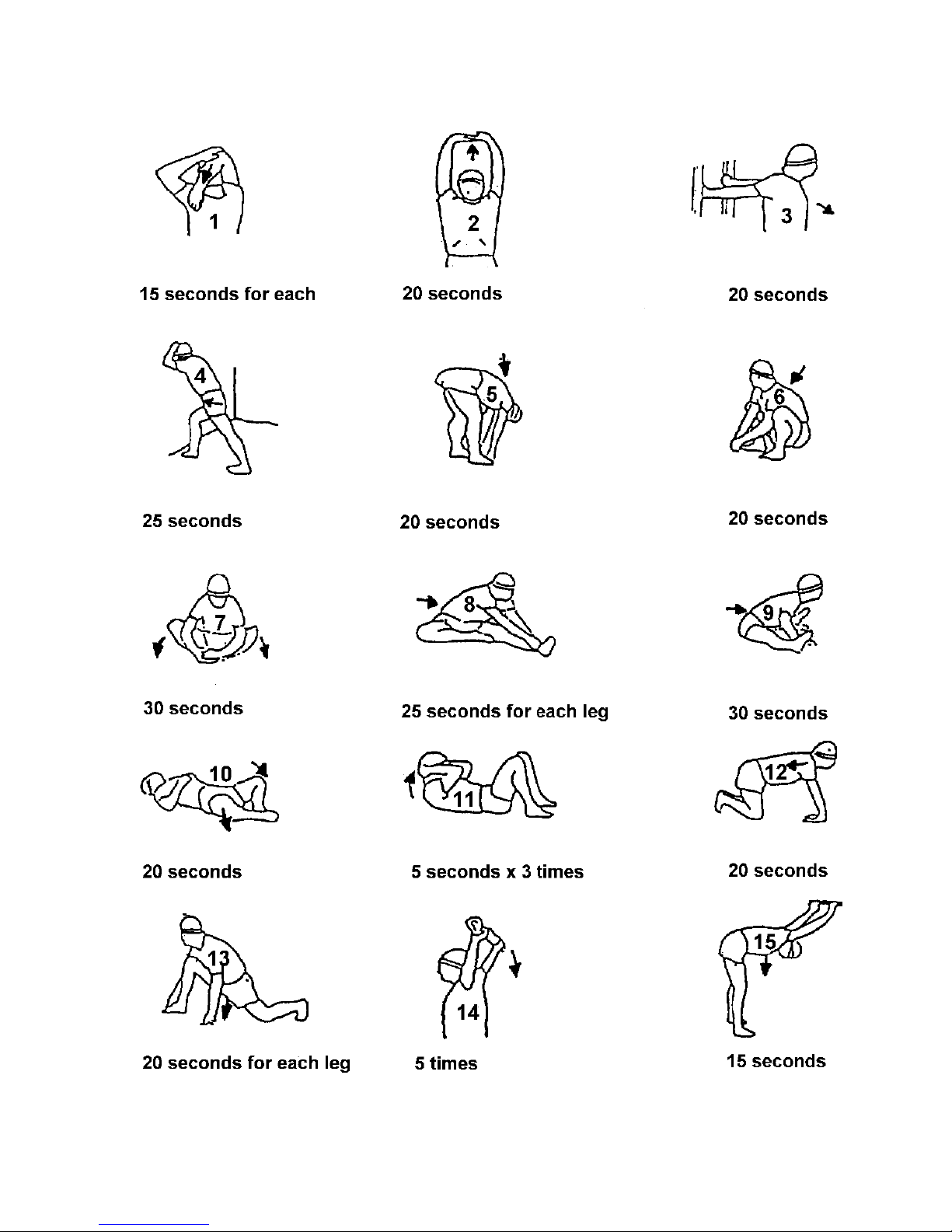
WARM-UP EXERCISE
3
ASSEMBLY STEPS
K-24
4
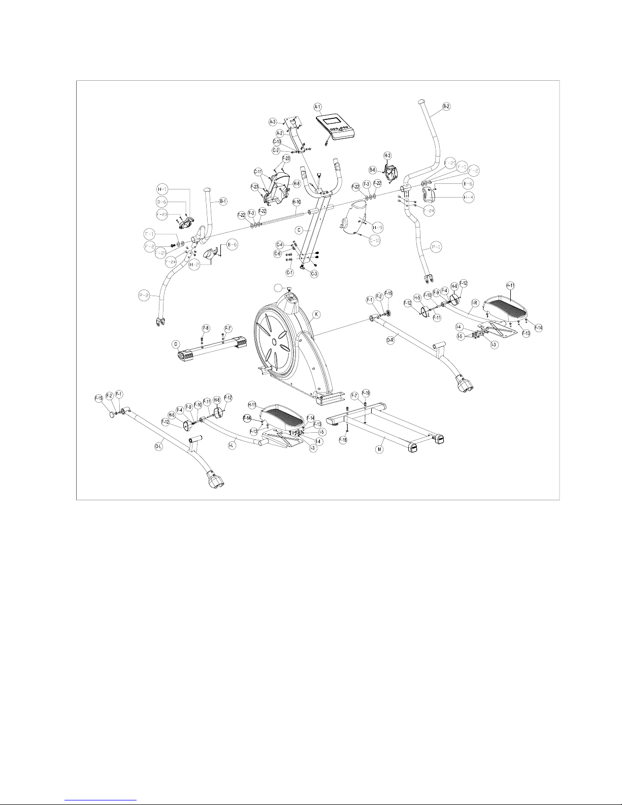
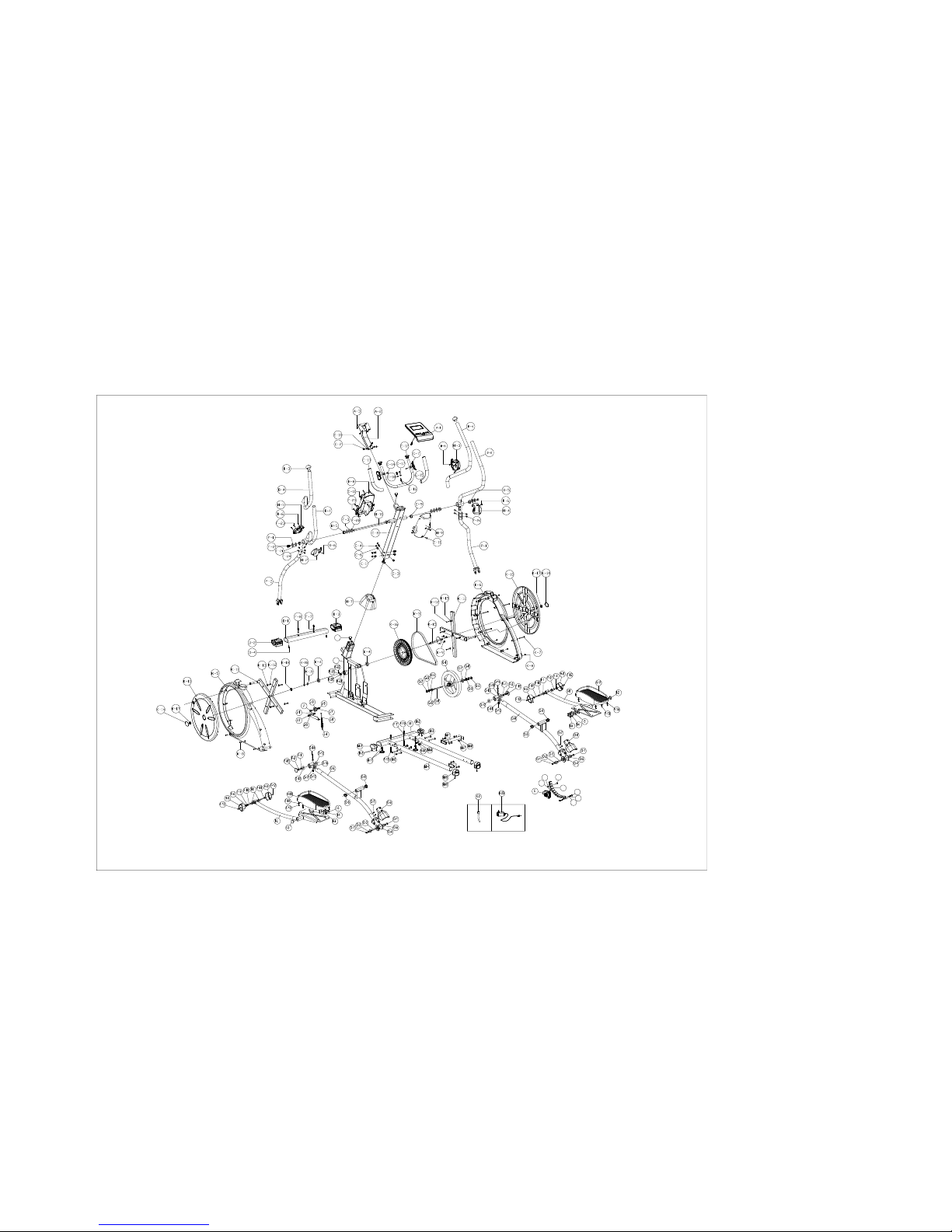
COMPLETE BIKE ASSEMBLY
E-5
E-4
E-3
E-2
E-7 E-6
E-1
K-1
K-24

5
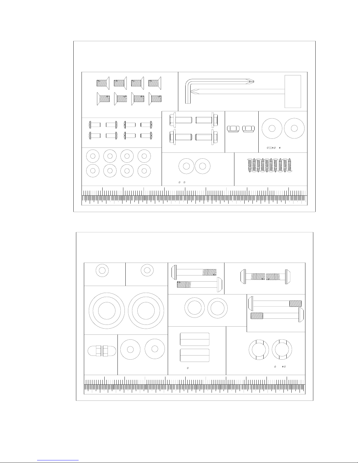
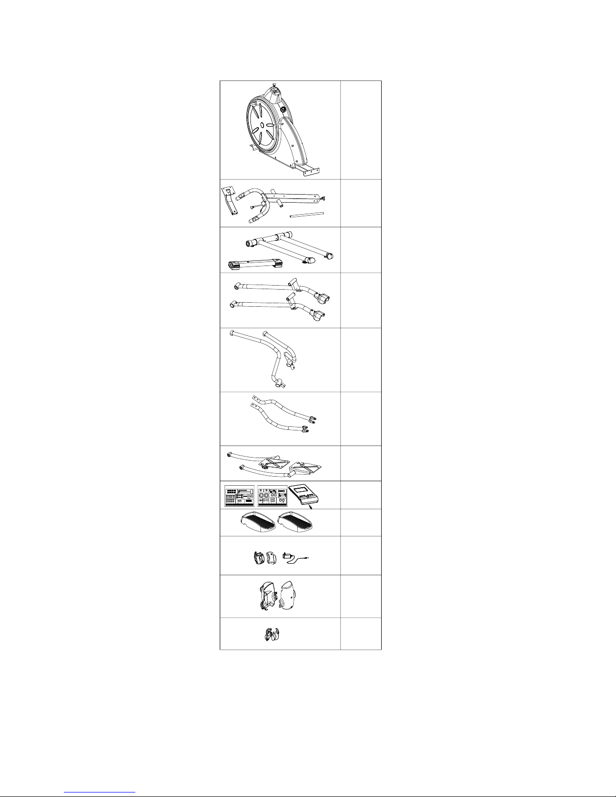
PARTS LIST AND TOOLS
NO.
DESCRIPTION
Q’TY
A-1
Console
1SET
A-2
Console plate
1SET
A-3
Screw
4PCS
B-1
Upper handlebar (L)
1SET
B-2
Upper handlebar (R)
1SET
B-3
End cap
2PCS
B-4
Foam grip
2PCS
B-5
Bushing
4PCS
B-6
Screw
4PCS
C
Handlebar post set
1SET
C-1
Flat Washer
7PCS
C-2
Screw
3PCS
C-3
Cable wire
1SET
C-4
Screw
7PCS
C-6
Spring washer
7PCS
C-7
Hand pulse
1SET
C-8
Handlebar post
1PCS
C-9
Bushing
2PCS
C-10
Flat Washer
3PCS
C-11
Screw
4PCS
C-12
End cap
2PCS
C-13
Foam grip
2PCS
C-14
Screw
2PCS
C-15
Front handlebar
1PCS
C-16
Wire
1PCS
C-17
Screw
2PCS
C-18
Semi washer
2PCS
D
Front stabilizer set
1SET
D-1
Front stabilizer
1PCS
D-2
End cap for front stabilizer (L)
1SET
D-3
End cap for front stabilizer (R)
1SET
D-4
Screw
2PCS
E
Gear box set
1SET
E-1
Magnetic set
1PCS
E-2
Hex. Screw
2PCS
E-3
Spring washer
2PCS
E-4
Flat Washer
2PCS
E-5
Adjustor for gear box
1PCS
E-6
Screw
1PCS
E-7
Hex. Nut
1PCS
F
Screw set
1SET
F-1
Flat Washer
4PCS

6
F-2
Nylon nut
4PCS
F-3
Wave washer
2PCS
F-4
Nut
2PCS
F-7
Semi washer
4PCS
F-8
Screw
2PCS
F-9
Flat Washer
2PCS
F-10
Bushing
2PCS
F-11
Screw
2PCS
F-12
Screw
4PCS
F-13
Screw
8PCS
F-14
Flat Washer
8PCS
F-15
Cover of screw
2PCS
F-16
Bushing wrench
1PCS
F-17
Hex wrench
1PCS
F-18
Screw
2PCS
F-19
Nut
2PCS
F-21
Plastic washer
2PCS
F-22
Flat Washer
4PCS
F-23
Screw
10PCS
F-24
Screw
8PCS
G
Flywheel set
1PCS
G-1
Flywheel
1PCS
G-2
Nut
2PCS
G-3
Nut
3PCS
G-4
Flat Washer
1PCS
G-5
Bearing
1PCS
G-6
Flywheel axle
1PCS
G-7
Bearing
1PCS
G-8
Bushing
1PCS
H-1
Front cover for upper handlebar(L)
1PCS
H-2
Rear cover for upper handlebar(L)
1PCS
H-3
Front cover for upper handlebar(R)
1PCS
H-4
Rear cover for upper handlebar(R)
1PCS
H-5
Left cap of lower handlebar
2PCS
H-6
Right cap of lower handlebar
2PCS
H-7
Upper cap of handlebar post
1PCS
H-8
Front cover of handlebar of post
1PCS
H-9
Rear cover of handlebar of post
1PCS
H-10
Fixed shaft of handlebar
1PCS
H-11
Pedal set
2PCS
I-L
Left pedal set
1PCS
I-R
Reft pedal set
1PCS
I-1
Sleeve
4PCS
I-2
End cap of pedal
2PCS

7
I-3
Connector plate for pedal arm
2PCS
I-4
Flat Washer
6PCS
I-5
Screw
6PCS
J
Idler set
1SET
J-1
Screw
1PCS
J-2
Nut
1PCS
J-3
Flat Washer
1PCS
J-4
Spring
1PCS
J-6
Screw
1PCS
J-7
Flat Washer
1PCS
J-8
Screw
1PCS
J-9
Idler wheel
1PCS
K
Main frame set
1SET
K-1
Main frame
1PCS
K-2
DC wire
1PCS
K-3
Belt
1PCS
K-4
Bearing
2PCS
K-5
Chain cover (Left)
1PCS
K-6
Chain cover (Right)
1PCS
K-7
Screw
6PCS
K-8
Screw
8PCS
K-9
Nut
3PCS
K-10
Disc
2PCS
K-11
Cross bar
2PCS
K-12
Screw
8PCS
K-13
Flat Washer
8PCS
K-14
Cap of disc
2PCS
K-15
Axle set
1PCS
K-16
Drive pulley
1PCS
K-17
Nut
2PCS
K-18
C ring
1PCS
K-19
Wave washer
1PCS
K-20
Flat Washer
1PCS
K-21
Sensor bracket
1PCS
K-22
Screw
1PCS
K-23
Adapter
1PCS
K-24
Servo motor wire
1PCS
K-25
Flat Washer
1PCS
K-26
Wire
1PCS
M
Rear stabilizer set
1SET
M-1
Slider tube
1SET
M-2
End cap
2PCS
M-3
Screw
4PCS
M-4
Slider
2PCS

8
M-5
Adjusting cap
2PCS
M-6
Screw
2PCS
M-7
Screw
4PCS
M-8
Semi washer
12PCS
M-9
Screw
4PCS
M-10
Nut
4PCS
M-11
Adjustable foot cap
2PCS
O-L
Linkage of left pedal set
1PCS
O-R
Linkage of right pedal set
1PCS
O-1
Screw
4PCS
O-2
Flat Washer
4PCS
O-3
Fix tube of roller
2PCS
O-4
Wheel
2PCS
O-5
Bearing
4PCS
O-6
Cap of roller
2PCS
O-7
Screw
4PCS
O-8
Bushing
4PCS
O-10
Wave washer
2PCS
O-11
Nut
4PCS
O-12
Bearing
4PCS
O-14
Screw
2PCS
O-15
Bracket of pedal tube
2PCS
P-1
Lower handlebar (R)
1PCS
P-2
Lower handlebar (L)
1PCS
9
2
ASSEMBLY INSTRUCTIONS
1
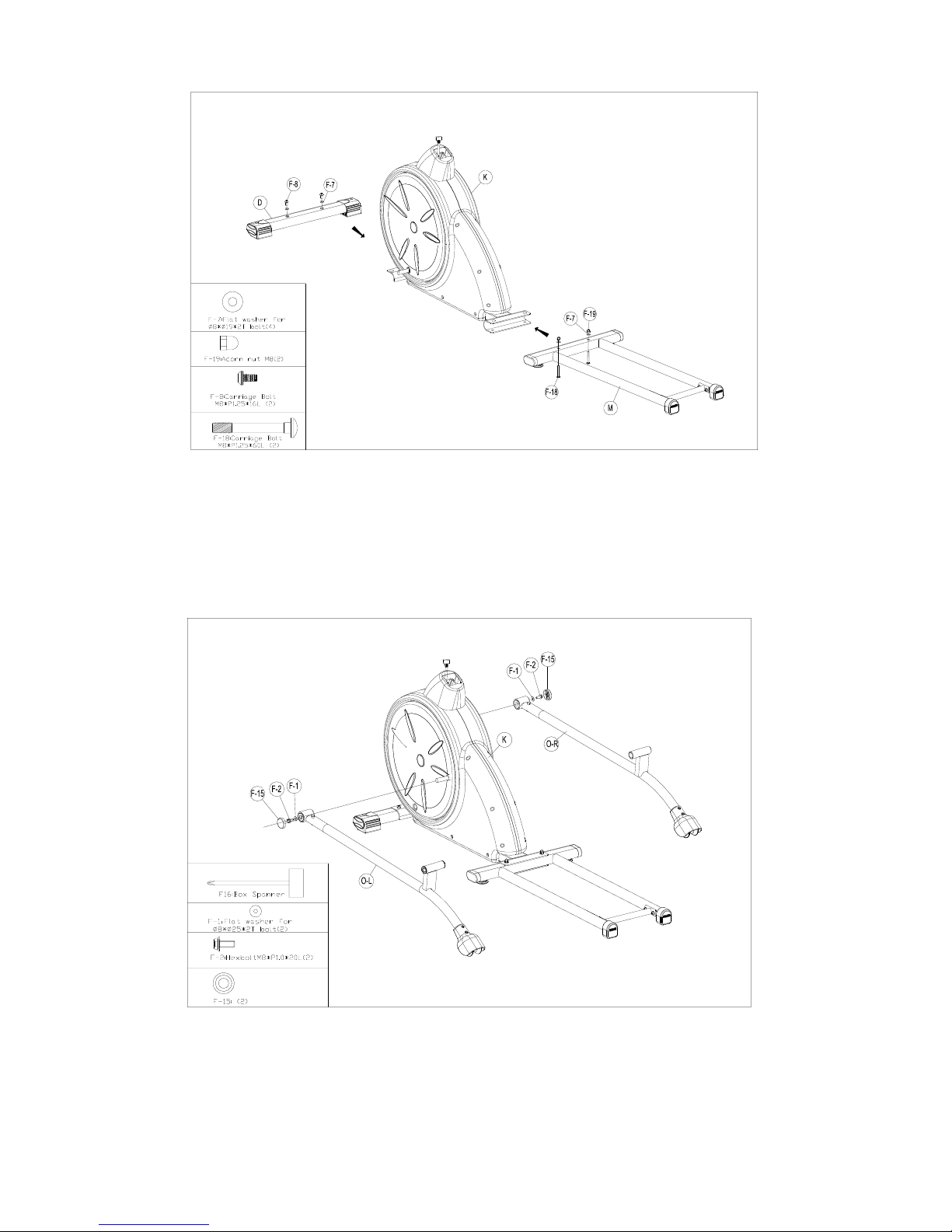
1. Securely fasten the Front stabilizer (D) to the Main frame (K) by using 2 screws (F-8).
2.Securely fasten the Rear stabilizer (M) to the frame (K) by using 2 flat washer (F-7),
2 Screws (F-18) and 2 Nut (F-19).
1. Assemble the Left crank arm (O-L) to the Crank (K-11) by using 1 Flat washer (F-1), 1 Nylon screw (F-2),
and 1 Cover for screw (F-15).
2. Assemble the Right crank arm (O-R) to the Crank (K-11) by using 1 Flat washer (F-1), 1 Nylon screw (F-2),
and 1 Cover for screw (F-15).

10
3
1. Connect the Cable wire (upper) (C-3) to the Cable wire (lower) (K-24)
2. Through the Handlebar post set (C) by the cover of handlebar post (H-7) to the main frame (K-1) with 4 Flat
washers (C-1), 4 Screws(C-4) and 4 Spring washers (C-6).
3. Install the Left and Right upper handlebar (B-1 & B-2) to the Axle for handlebar (H-10) with 1 Flat washer (F-22),
1 Wave washer (F-3), 1 Plastic (F-21), 1 Flat washer (F-1) and 1 Nut (F-2) each side.
4. Then attach the Left and Right upper handlebar (B-1 & B-2) to the Left and Right lower handlebar
(P-2 & P-1) by using 4 screws(F-24).

11
3
1
2
2
1
3
4
1. Attach the Linkage tube of left and right pedal (I-L & I-R) to the left and right crank arm(O-L & O-R), and then
fasten it with 1 Pedal connector (I-3), 3 Flat washers (I-4), and 3 Screws (I-5) each side.
2. Attach the Linkage tube of left and right pedal (I-L & I-R) to the left and right lower handlebar (P-2 & P-1), and
then fasten it with 1 screw (F-11), 1 bushing(F-10), 1 flat washer(F-9) and 1 nut(F-4) each side.

12
5
1. Assemble the Pedals (H-11) to Linkage tube of left and right pedal (I-L & I-R) with 8 Screws (F-13) and
8 flat washers (F-14).

13
7
1. Attach support tube(A-2) into handlebar post(C-8) by 2 flat washers(C-1) and 2 screws(C-2).
2. Attach Front cover of handlebar post(H-8) and Rear cover of handlebar post(H-9) to handlebar post(C-8)
by 4 screws(C-11), 4 screws(F-23).
3. Assemble Front cover for upper handlebar Left (H-1) and Rear cover for upper handlebar Left (H-2) by
2 screws (B-6) and 2 screws(F-23).
4. Assemble Front cover for upper handlebar Right (H-3) and Rear cover for upper handlebar Right (H-4)
by 2 screws (B-6) and 2 screws(F-23).

14
8
1.Fix the computer (A-1) with 4 screws (A-3).
2. Plug-in the adaptor (K-23) onto the machine.

15
16
UF855R
F-2:HexboltM8*P1.0*20L
(movabhandlebar)(4)
F-14: Flat Washer ?6*?16*1T(8)
F-13:Screws M5*12L(8)
F16:Box Spanner(1)
F-7:Flat Washer for
8* 19*2T bolt(4)
F-4:lock nut for
M8 bolt (2)
F17:Allen Key(1)
F23:Screws M3*14L 10PCS
F-21:teflon washer
25 0.5T bolt(2)
F24:allen bolt M8*12L(8)
F-11: Allen Bolt M8*P1.25*50L(2)
UF855R
F-1:FlatWasher ?8*?25*2T bolt(4)
F-9:Flat Washer
?8*?16*1T(2)
F-3:Curved Washer 17.5 25*0.3T(2)
F-15¡ G¡ ]2¡ ^
F-10: 16*36.5L Bolt(2)
F-18:Carriage Bolt M8*P1.25*65L (2)
F-6: Acorn Nut M8(2)
F-8: Allen Bolt M8*P1.25*16L(2)
F-22: Flat Washer ?17.5*?25*0.3T(4)
F-5;Curved Washer
?8*?19*2T(2)
HARDWARE KITS
17
1
1/1
1/1
1/1
1/1
1/1
1/1/1
UF855R
F-2:HexboltM8*P1.0*20L
(movabhandlebar)(4)
F-11: Allen Bolt M8*P1.25*5 0L(2)
F-14:Flat Washer ?6*?16*1T(8)
UF855R
F-1:FlatWasher ?8*?25*2T bolt(4)
F-13:ScrewsM5*12L(8)
F-9:FlatWasher
?8*?16*1T(2)
F16:BoxSpanner(1)
F-7:FlatWasher for
8* 19*2T bolt(4)
F-4:locknut for
M8bolt (2)
F-3:CurvedWasher 17.5 25*0.3T(2)
F17:AllenKey(1)
F-15¡G¡]2¡^
F-10: 16*36.5L Bolt(2)
F-18:CarriageBolt M8*P1.25* 65L(2)
F-6:Acorn Nut M8(2)
F-8:A l lenB o ltM8*P1.25*16L(2)
F23:ScrewsM3*14L 10PCS
F-21:teflonwasher
25 0.5T bolt(2)
F-22:Flat Washer ?17.5*?25*0.3T(4)
F24:allenbolt M8* 12L(8 )
F-5;CurvedWasher
?8*?19*2T(2) 1/1/1
1/1/1
1/1
1/1
1/1
18
INSTRUCTION MANUAL OF SM7294-67
[BUTTON FUNCTION]
MODE
In stop mode, MODE is to confirm all exercise data setting, and
enter into program.
RESET
In stop mode, press the button back to main menu.
START/STOP
To start or stop exercise.
RECOVERY
To test hear rate recovery status.
UP
To select training mode and adjust function value up.
DOWN
To select training mode and adjust function value down.
BODY FAT
For body fat measurement.
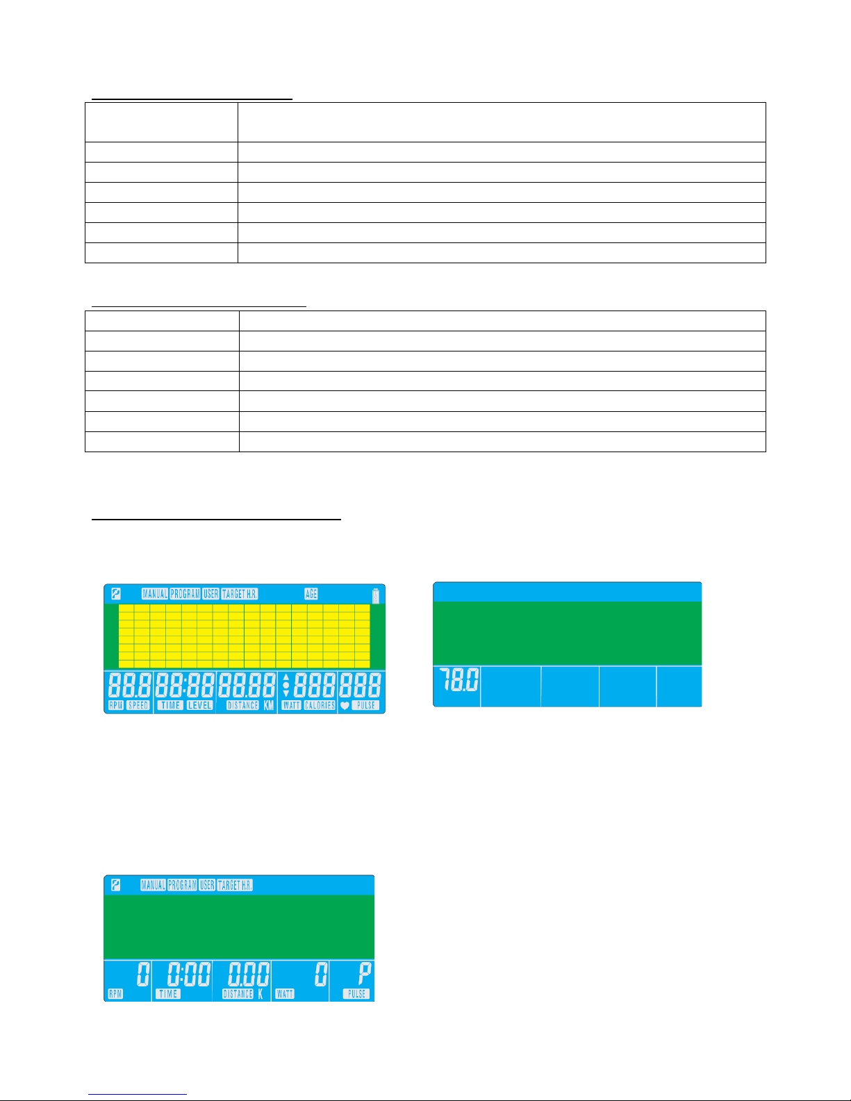
[DISPLAY EXERCISE DATA]
TIME
Display range 0:00~99:99 ; Setting range 0:00~99:00
DISTANCE
Display range 0.00~99.99 ; Setting range 0.00~99.90km
CALORIES
Display range 0~9999 ; Setting range 0~9990
PULSE
Display range P-30~230 ; Setting range 0-30~230
WATT
Display range 0~999 ; Setting range 10~350
SPEED
0.0~99.9km
RPM
0~999
[OPERATION PROCEDURE]
1. Connect power supply and computer will power on with a long beep sound, LCD
display all segments (drawing A) for 2 seconds and wheel diameter 78”.
2. There are 4 separate user personal data storage files listed from U1 to U4. User will be asked
to enter sex, age, height and weight before enter into main menu. The first user number
displayed will be the last user number selected. Turning the UP and DOWN to select the
required user number, U1 to U4, press MODE.
3. In main menu, user may press UP or DOWN to select MANUAL (w/ WATT control)
PROGRAM (12 profiles) USER PROGRAMTARGET H.R.
4. Quick Start in Manual mode:
In main menu, user may press START/STOP to start workout in manual mode. All exercise
value (TIME/ SPEED / DISTANCE / CALORIES) will counting up from zero, and level can

19
be adjusted during workout.
5. Manual :
Before exercise in Manual mode, user my set up LEVEL, TIME, DISTANCE, CALORIES and
PULSE target by press UP or DOWN to upward or downward.
6. Watt control in Manual mode:
To activate WATT control function, user may also preset WATT value while in Manual
mode.
The preset watt value 120 is flashing on screen. User may press UP or DOWN to set target
value from 10 to 350. Press MODE button for confirmation.
The resistance level will automatically adjust to the preset WATTS value regardless of Speed
(except for very slow Speeds and higher WATTS settings where the resistance can only
increase to level 32, maximum).
7. PROGRAM:
Press UP or DOWN to select Program with 12 profiles and press MODE to confirm.
User my set up LEVEL, TIME, DISTANCE, CALORIES and PULSE target by press UP or
DOWN to upward or downward.
8. H.R.C.:
Before exercise in H.R.C. mode, user may select 55%, 75%, 90% or Target pulse.
Computer will automatically calculate user’s age and come up with certain target
bpm.
This manual suits for next models
1
Table of contents
Popular Elliptical Trainer manuals by other brands


NordicTrack
NordicTrack E9 Zl Elliptical Manual Del Usuario

Life Fitness
Life Fitness X3 Cross-Trainers owner's manual

Pro-Form
Pro-Form SpaceSaver 700 PFIVEL74313.0 user manual

Life Fitness
Life Fitness ARCTIC SILVER SUMMIT 95LE-0XXX-01 parts manual

Life Gear
Life Gear 93580N owner's manual

NordicTrack
NordicTrack NTEL71420.1 user manual