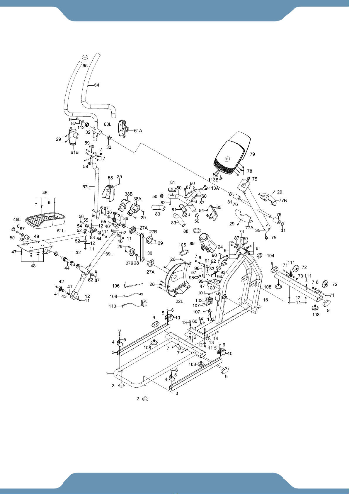
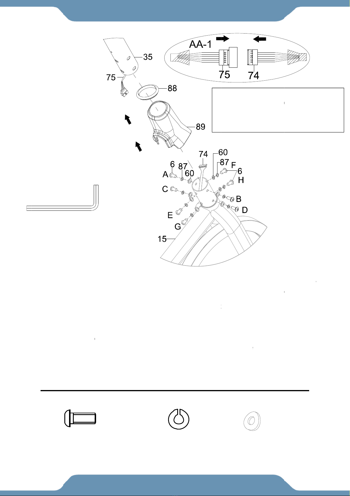
Fitness Reality X CLASS 710 ST User manual

2366.1
‐011717
7
FL
Y
IMPORT
A
this own
e
may var
y
7
10S
T
Y
WH
E
A
NT: Read
e
r’s manu
a
y
from this
T
SM
A
E
EL
E
all instruc
t
a
l for futur
e
photo an
d
A
RT T
E
LLIP
T
t
ions care
f
e
referenc
e
d
, subject t
o
ECH
N
T
ICA
L
f
ully befor
e
e
. The spe
c
o
change
w
N
OL
O
L
TR
A
e
using thi
s
c
ifications
w
ithout no
t
O
GY
A
INE
R
s
product.
of this pr
o
t
ice.
R
Retain
o
duct

PLEASE DO NOT RETURN THIS PRODUCT TO THE STORE.
STOP. Contact customer service if you have any questions
regarding assembly or proper operation of the machine.
Email us at:
Service@paradigmhw.com
Or call us at:
1-844-641-7920
Hours:
8:00 am to 5:00 pm (PST) Daily
STOP
ARRÊT
ALTO

S
L
I
O
P
H
A
C
T
T
W
P
S
ERVIC
E
L
ABEL P
MPORT
A
O
VERVI
E
P
ARTS
L
H
ARDW
A
A
SSEM
B
C
OMPU
T
T
RANSP
T
ROUBL
W
ARRA
N
P
ARTS
R
E
---------
-
LACEM
E
A
NT SA
F
E
W DRA
W
L
IST -----
-
A
RE & T
O
B
LY ------
-
T
ER CO
N
ORT ----
-
E SHOO
N
TY -----
-
R
EQUES
T
T
A
-
-----------
-
E
NTS ----
F
ETY GU
W
ING ---
-
-----------
-
O
OLS P
A
-
-----------
-
N
SOLE--
-
-
-----------
TING &
M
-
-----------
-
T
FORM
A
BLE
O
-
----------
-
-----------
-
IDELIN
E
-----------
-
-
----------
-
A
CK -----
-
-
----------
-
-
-----------
-
-----------
-
M
AINTE
N
-
----------
-
-----------
1
O
F CO
-
-----------
-
-
-----------
E
S --------
-
-
-----------
-
-----------
-
-
-----------
-
-
-----------
-
-----------
-
-
-----------
N
ANCE -
-
-----------
-
-----------
-
NTEN
T
-
----------
-
-----------
-
-
----------
-
-----------
-
-
----------
-
-
----------
-
-
----------
-
-
-----------
-
-----------
-
-----------
-
-
----------
-
-
-----------
T
S
-----------
-
-
-----------
-
-----------
-
-
-----------
-
-----------
-
-
-----------
-
-----------
-
-
----------
-
-
-----------
-
-
-----------
-
-----------
-
-
----------
-
-
----------
-
-----------
-
-
----------
-
-----------
-
-
----------
-
-
----------
-
-
----------
-
-
-----------
-
-----------
-
-----------
-
-
----------
-
-
-----------
----- 2
-
-----
3
-----
4
-
-----
5
-----
7
-
-----
9
----- 1
0
-
---- 2
2
-
--- 2
6
-
---- 2
7
---- 2
8
---- 2
3
4
5
7
9
0
2
6
7
8
9

IM
Fo
r
su
p
F
o
s
e
Re
s
E
m
pe
a
W
e
w
w
Tol
1-8
4
(8:
Re
s
Ple
Fo
r
the
Pa
r
11
8
Cit
y
PORT
A
r
damage
d
p
port, ple
a
o
r The
e
rvice
@
s
ponse Ti
m
ailing us
w
a
k busine
s
e
bsite
:
w
w.pa
r
l-Free:
4
4-641-79
0
0 AM -
5
s
ponse ti
m
ase have
Your na
m
Phone n
Model n
u
Serial n
u
Part nu
m
Proof of
r
damage
d
store.
r
adigm H
e
8
9 Jellick
A
y
of Indu
s
A
NT: FO
d
or defec
a
se conta
c
Best
S
@
para
d
me: 1-2 B
w
ith the i
n
s
s hours
:
r
adig
m
20
5
:00 PM
m
e may v
a
the follo
w
m
e
umber
u
mber
u
mber
m
ber
Purchas
e
d
or defec
e
alth & W
e
A
ve.
s
try, CA 9
1
R NOR
T
tive prod
u
c
t our cu
s
S
ervice
d
igmh
w
usiness
D
n
formatio
n
m
hw.co
m
Pacific
S
a
ry via ca
l
w
ing infor
m
e
tive prod
u
e
llness, In
1
748, US
A
S
T
H AM
E
u
ct, quest
s
tomer se
r
, plea
s
w
.com
D
ays
n
above
w
m
S
tandar
d
l
ling
m
ation re
a
u
ct pleas
e
c.
A
2
S
ERVI
C
E
RICA
O
t
ions, repl
r
vice dep
a
s
e Em
a
w
ill be the
d
Time,
D
a
dy when
e
contact
o
C
E
O
NLY
acement
p
a
rtment b
y
a
il:
best met
h
D
aily)
requesti
n
o
ur custo
m
p
arts or a
n
y
the belo
h
od to rec
e
n
g for ser
v
m
er servi
c
n
y other
s
o
w metho
d
e
ive a res
v
ice:
c
e before
s
ervice
d
s:
ponse du
r
returning
r
ing
to

L
L
ABEL
3
PLAC
E
E
MEN
T
T
S

Ba
s
wh
e
1.
2.
3.
4.
5.
6.
7.
8.
9.
10.
11.
12.
13.
14.
15.
16
es
p
pr
o
O
w
s
ic preca
u
e
n using
t
Before e
x
warm-up
e
Make sur
e
damaged
.
Make sur
e
This equi
p
the groun
d
Wear pro
p
may get c
Make sur
e
Do not op
Do not us
e
Only perf
o
discontin
u
Only one
at all time
s
Be carefu
have the
p
Hold onto
This prod
u
If you fe
e
immediat
e
DO NOT
p
.The m
WAR
N
p
ecially i
m
o
blems.
CAU
T
ner’s Man
I
M
u
tions s
h
t
his equi
p
x
ercising a
n
e
xercises f
o
e
all the co
.
e
that the h
a
p
ment sho
u
d
is recom
m
p
er fitness
a
c
aught by a
n
e
all the co
m
erate the e
q
e or store t
h
o
rm mainte
n
u
e usage o
f
person sh
o
s
. This ma
c
l to always
p
edals at t
h
the handle
u
ct require
s
e
l any che
s
e
ly, and co
n
p
edal in re
v
aximu
m
N
ING:
B
m
portant f
o
T
ION: R
ual for fut
M
POR
T
h
ould alw
a
p
ment. Re
a
n
d to avoi
d
o
r each mu
s
mponents
a
a
rdware (b
o
u
ld be plac
e
m
ended.
a
pparel wh
e
n
y part of t
h
m
ponents
a
q
uipment i
n
h
e equipm
e
n
ance or a
d
f
the equip
m
o
uld be on t
c
hine is de
s
hold onto
h
eir lowest
p
bars and u
s
s
a minimu
m
s
t pains, n
a
n
sult your p
v
erse.
m
weig
h
B
efore be
g
o
r the peo
p
ead all in
s
ure refere
n
T
ANT
S
a
ys be f
o
a
d all of t
h
d
injuring
y
s
cle group.
a
re not da
m
o
lts, nuts, a
e
d on a sta
b
e
n using thi
h
e equipme
a
re not dam
a
n
wet or mo
e
nt outdoor
s
d
justments
t
m
ent and c
o
h
e equipm
e
s
igned for a
d
the handle
b
p
oint when
s
s
e both the
m
of 6 squa
a
usea, dizz
hysician b
e
h
t capa
c
g
inning a
n
p
le who a
r
s
tructions
n
ce.
4
S
AFET
Y
o
llowed, i
n
h
e guideli
n
y
our muscl
e
m
aged and
a
nd screws)
b
le, flat sur
f
s equipme
n
nt.
aged and
a
ist conditio
n
s
. This equi
t
hat are ins
t
o
nsult with
o
e
nt at a tim
e
d
ults only.
bars when
s
tepping o
n
pedals in t
a
re feet aro
u
z
iness, or
s
e
fore contin
u
c
ity for
n
y exercis
r
e over 3
5
carefully
Y
GUI
D
n
cluding
n
es befor
e
e
s, it is hi
g
are in wor
k
are all tigh
f
ace. Using
n
t. Do not
w
a
re in worki
n
n
.
pment is f
o
t
ructed in t
h
o
ur custom
e
e
. Keep chi
you’re mo
u
n
or off.
a
ndem to e
u
nd for saf
e
s
hortness o
u
ing.
t
his pr
o
e progra
m
5
years ol
d
before o
p
D
ELIN
E
t
he follo
w
e
using t
h
g
hly recom
m
k
ing orde
r
b
t
.Check th
e
a mat or si
w
ear loose
c
n
g orde
r
be
f
r househol
d
is manual.
S
e
r service.
ldren and
p
u
nting and
d
nsure a sm
operation.
f
breath, y
o
o
duct i
s
m
consult
d
or who
h
p
erating t
h
E
S
w
ing safe
t
h
is equip
m
m
ended th
b
efore usin
g
e
m on a we
e
mila
r
, cove
c
lothing or
a
fore using.
d
use only.
Should an
y
p
ets away f
r
d
ismountin
g
m
ooth, effec
t
o
u should
s
300 lb
s
your phy
s
h
ave pre-
e
h
is produ
c
t
y guidel
i
m
ent.
at you per
f
g
. Do not
u
e
kly basis.
ring materi
a
a
ccessorie
s
y
problems
a
r
om the pr
o
g
. Be care
f
t
ive workou
stop exerc
s/
136 k
g
s
ician. Th
i
e
xisting h
e
c
t. Retain
i
nes
f
orm
u
se if
a
l on
s
that
a
rise,
o
duct
f
ul to
t.
ising
g
s.
i
s is
e
alth
this

O
O
VERV
I
5
I
EW D
R
R
AWI
N
N
G

OVER
V
6
V
IEW
D
D
RAW
I
NG

No
1
2
3
4
5
6
7
8
9
10
11
12
13
14
15
16
17
18
19
20
21
22
L
22
R
23
24
25
26
27
A
27
B
28
. Descri
p
Rear St
a
Foot Pa
d
Aluminu
Track T
u
Tapered
Hexago
n
Lock N
u
Washer
Elliptica
l
Track T
u
77.5*60
*
Locknut
Washer
Carriag
e
Hexago
n
Main Fr
a
Washer
Bearing
Bolt M8
Pulley
Axle
Belt
L
Left Axl
e
R
Right A
x
Cross
R
Screw
S
Cross
R
M5*12
Right A
x
Cross
R
Screw
S
A
Left Cra
B
Right C
r
Hexago
n
p
tion
a
bilizato
r
d
u
m Track ra
i
u
be End ca
d
Spacer φ1
n
Socket B
o
u
t M8
φ8
l
Tube End
u
be End C
a
*
45
M10
φ10 Zinc
B
e
Bolt M10*
n
Socket B
o
a
me
on Φ19
e
Cover
x
le Cover
R
ecessed P
a
S
T4.2*10
R
ecessed P
a
x
le Cover
R
ecessed P
a
S
T4.2*25
nk Cover
r
ank Cover
n
Nuts with
i
l
p
1*φ8.2*3.5
o
lt M8*20
Cap
a
p(Front)
B
lack
60
o
lt M8*100
a
n Head T
a
a
n Head S
c
a
n Head T
a
Flange M1
P
A
Q
t
1
2
2
2
4
2
1
8
4
2
1
1
4
2
2
1
2
2
2
1
1
1
1
1
a
pping
4
c
rew
2
1
a
pping
6
4
4
0*1.25
2
7
A
RTS
L
t
y
N
1
2
2
3
2
3
2
3
4
3
5
3
6
3
8
3
4
3
2
3
2
3
4
3
2
3
2
4
1
4
2
4
2
4
2
4
1
4
1
4
1
4
1
4
1
4
4
4
2
5
1
5
6
5
4
5
4
5
2
5
L
IST
N
o. Desc
r
2
9 Cross
Screw
3
0 Crank
3
1 Wave
W
3
2 Nylon
3
3 Wash
e
3
4 Crank
3
5 Uprig
h
3
6 Wash
e
3
7 Hexag
3
8
A
Crank
3
8B Crank
3
9L Left
W
3
9R Right
W
4
0 Wash
e
4
1 Wheel
4
2 Wheel
4
3 Hexag
4
4 Pedal
A
4
5 Hexag
4
6L Left P
e
4
6R Right
P
4
7 Wash
e
4
8 Lock
N
4
9 Bushi
n
5
0 Roun
d
5
1L Left P
e
5
1R Right
P
5
2 Nylon
5
3 U-Bra
c
5
4 Bushi
n
r
iption
Recessed
P
ST4.2*16
A
ssembly
W
asher Φ1
Bushing φ
3
e
r Φ6
U-Bracket
t Post
e
r Φ8
on Nuts wi
t
Bracket (u
p
Bracket (lo
w
heel Arm
W
heel Arm
e
r φ20*φ10
.
Bushing φ
1
on Bolt M1
0
A
xle
on Bolt M6
*
e
dal
P
edal
e
r Φ6
N
ut M6
n
g φ38*φ19
Tube End
e
dal Assem
P
edal Asse
m
Bush φ28*
φ
c
ket
n
g φ32*φ10
P
an Head
T
9
3
8.1*φ19.1
*
t
h Flange
M
p
per)
wer)
.
5*1.0
16*φ10*5
0
*45
*
18,
9
*32
Cap
m
bly
m
bly
φ
14*φ10.2
*
0
*16
Q
T
apping
*
15.38
M
10*1
*
10
Q
ty
20
2
2
12
1
1
1
4
2
2
2
1
1
4
4
2
2
2
8
1
1
10
8
2
4
1
1
8
1
4

No
55
56
57
L
57
R
58
59
60
61
A
61
B
62
63
L
63
R
64
65
66
67
68
69
70
71
72
73
74
75
76
77
A
77
B
78
79
80
81
82
. Descri
p
Hexago
n
Hexago
n
L
Left Lo
w
R
Right L
o
Pivot C
o
Hexago
n
Curve
W
A
Front H
a
B
Rear H
a
Washer
L
Left Ha
n
R
Right H
a
Handle
G
End Ca
p
Flywhe
e
Hexago
n
Ball Be
a
Fly Wh
e
Flywhe
e
Hexago
n
Wheel
A
Front St
Mainfra
m
Upright
W
Bushing
A
Front H
a
B
Rear H
a
Cross
R
Consol
e
Handle
b
Pulse P
l
Cross T
a
p
tion
n
Socket B
o
n
Socket B
o
w
er Handle
o
wer Handl
e
o
ver
n
Socket B
o
W
asher Φ8
a
ndlebar S
h
a
ndlebar S
h
Ф38Ф8*1.
7
n
dlebar
a
ndlebar
G
rip
p
e
l
n
Nut M12*
a
ring
e
el Axle
e
l Bushing
φ
n
Socket B
o
A
ssembly φ
6
t
abilizer
m
e Wire L6
W
ire L950
M
g
φ38*φ19.
5
a
ndle Joint
a
ndle Joint
C
R
ecess Hea
d
e
L:50MM
b
a
r
l
ate
a
pping Scr
e
o
lt M10*55
o
lt M10*70
Bar Assem
b
e
Bar Asse
m
o
lt M8*45
h
ield
h
ield
7
5
1.25
φ
16*φ12*9.
5
o
lt M8*42
6
8*24
00MM
M
M
5
*64.3
Cover
C
over
d
Screw M
4
e
w ST4.2*2
P
A
Qt
y
4
2
b
ly 1
m
bly 1
2
6
1
8
2
2
4
1
1
2
2
1
3
2
1
5
1
2
2
1
1
1
2
1
1
4
*10 4
1
1
2
5 2
8
A
RTS
L
y
N
8
8
8
8
8
8
8
8
9
9
9
9
9
9
9
9
9
9
1
1
1
1
1
1
1
1
1
1
1
1
1
1
1
L
IST
N
o. Desc
r
8
3 Handl
e
8
4 Cross
Wash
e
8
5 Bottle
8
6 Bushi
n
8
7 Spring
8
8 Uprig
h
8
9 Uprig
h
9
0 Cover
9
1 Magn
e
9
2 Magn
e
9
3 Hexag
9
4 Hexag
9
5 Spring
9
6 Magn
e
9
7 String
9
8 Cross
9
9 Socke
t
00 Magn
e
01 Hexag
02 Motor
03 Senso
04 Roun
d
05 Ellipti
c
06 Motor
07 Cross
08 Foot
P
09 Wire
6
10 Trans
f
11 Carrai
g
12 Wash
e
13A Pulse
S
13B Pulse
S
r
iption
e
Bar Grip
Recess He
e
r M5*15
holder
n
g Nylon (φ
3
Washer Φ
8
h
t Rubber
R
h
t Cover
e
t 25.4*12.
7
e
t 25.4*25.
4
on Bolt M6
*
on Nut M6
φ7*45
e
t Plate
Plate
Recess He
t
Head Ca
p
e
t Ad
j
ust Br
a
on Socket
S
r 150MM
Tube End
c
al Tube Ri
n
Cord
Recess He
P
ad
00MM
o
rmer
g
e Bolt M1
0
e
r M8*25.4
S
ensor Wir
e
S
ensor Wir
e
e
ad Screw
w
38.1*φ16.
0
8
R
ing
7
*6.4
4
*6.35,
*60
e
ad Screw
M
p
Screw M6
a
cket
S
crew M6*
1
Cap
n
g
e
ad Screw
S
0
*55
r
es I
r
es II
Q
w
ith
5*15.38 )
M
4*10
*
15
1
10
S
T4.2*15
Q
ty
2
2
1
4
18
1
1
1
1
2
1
2
1
1
1
2
2
1
1
1
1
1
1
1
5
4
1
1
2
2
2
2

HA
R
R
DWA
R
9
R
E & T
O
O
OLS
P
P
ACK

St
e
1a.
the
are
tw
o
H
a
Too
l
W
r
e
p 1
Installin
g
Front St
a
facing ou
t
o
Locknut
s
a
rdwar
e
l
:
r
ench 13,1
g
the Fron
t
a
bilizer (7
3
t
wards. S
e
s
(11) and
e
:
7mm 1P
C
(111) Ca
r
2
P
t
Stabiliz
e
3
) with th
e
e
cure and
two Wash
r
riage Bo
l
P
CS
AS
e
r – Lift up
e
bracket
h
tighten th
e
ers (12) u
s
l
t
10
S
SEM
B
the front
o
h
oles on t
h
e
Front S
t
sing the 1
3
(12) Was
h
2 PCS
B
L
Y
o
f the Mai
n
h
e Main F
r
t
abilizer (
7
3
,17mm
W
h
er
n
Frame (1
r
ame (15).
7
3) with t
w
W
rench pr
o
(11)
L
2
5) and ali
g
.
Ensure t
h
w
o Carria
g
o
vided.
L
ock Nut
PCS
g
n the hol
e
h
at the wh
e Bolts (
1
e
s of
eels
1
11),

St
e
2a.
int
o
tw
o
(11
)
Wa
Ph
i
.
6
m
To
o
M
(14) He
x
B
e
p 2
Installin
g
o
the curve
o
Carriage
)
. Then o
n
shers (8)
,
llips Scre
m
m Allen
W
H
o
ls:
M
ulti Hex T
o
Screw
d
(13) Ca
2
x
agon So
c
B
olt 2pcs
g
the Rear
e
d bracket.
Bolts (1
3
n
the side
,
,
and two
e
wdriver, t
W
rench 1P
C
H
ardwa
r
o
ol with P
h
d
river 1P
C
rriage Bo
l
PCS
c
ket
Stabilize
r
Align the
3
), through
,
attach t
w
Locknut
s
he 13-17
m
C
r
e:
h
illips
AS
l
t (12
2
(8
)
2
r
–Lift the
h
oles on t
h
the top,
a
w
o Hexag
o
s
(7). Tigh
t
m
m Wren
c
13,17
m
11
S
SEM
B
2
) Washer
2 PCS
)
Washer
2 PCS
Main Fra
h
e Main F
r
a
nd secur
e
o
n Socke
t
t
en the B
o
c
hand the
m
m Wrenc
h
B
L
Y
(1
1
(
me (15) u
p
r
ame (15)
e
with two
t
Bolts (1
4
o
lts and N
6 mm All
e
h
1P
C
) Locknu
t
2 PCS
(
7) Lockn
u
2 PCS
p
and slid
e
and the R
e
W
ashers
4
), two C
u
uts with t
h
e
n Wrenc
h
t
u
t (60)
C
e
the Rea
r
R
ear Stabil
(12), and
t
u
rve Was
h
h
e Multi-
H
h
provided
C
urve Wa
s
2 PCS
r
Stabilize
r
izer (1). I
n
t
wo Lock
n
h
ers (60),
H
ex Tool
w
.
s
her
r
(1)
n
sert
n
uts
two
w
ith

St
e
3a.
Co
v
3b.
co
n
ont
o
3c.
ha
n
Wa
6m
6
T
Ha
e
p 3
Installin
g
v
er (89) o
n
Connect
i
n
necting th
o
the Mai
n
Installin
g
n
d tighteni
n
shers (60
)
m Allen
W
MUS
T
6
mm Allen
T
ool:
rdware:
(
6
g
the Upr
i
n
to the Up
i
ng the
W
e wires c
a
n
Frame (
1
g
the Upri
g
n
g the eig
h
)
.Once tol
W
rench pr
o
T
TIGH
T
Wrench 1
P
6
) Hexago
n
Bo
8pc
s
i
ght Cov
e
right Pos
t
W
ires – Co
a
refully tuc
k
1
5).
g
ht Post
-
h
t Hexago
n
d to do so
o
vided: A,
T
EN B
O
PC
n
Socket
lt
s
AS
e
r & Ring
t
(35). Hol
d
n
nect the
k
the wire
s
-
Secure t
n
Socket
B
after STE
P
B
, C, D, E
,
O
LTS IN
(87
)
12
S
SEM
B
–Slide t
h
d
the part
s
Upright
W
s
inside th
e
he Uprig
h
B
olts (6),
e
P
6 tighten
, F, G, an
d
SEQU
E
) Spring
W
8pcs
B
L
Y
h
e Uprigh
above th
e
W
ire (75)
t
e
tubes a
n
h
t Post (3
5
e
ight Spri
n
the bolts i
d
H.
E
NCE:
A
W
asher
W
T
B
A
t Rubber
e
bolt hold
s
t
o the Mai
n
n
d slide th
e
5
)to the
M
n
g Washe
n the follo
w
A
, B, C,
(60) Cur
v
8
p
W
ARNIN
G
HOROU
G
B
OLTS U
N
A
FTER C
O
Ring (88
)
s
for the f
o
nframe
W
e
Upright
M
ain Fra
m
e
rs (87), a
n
w
ing sequ
e
D, E, F,
v
e Washe
p
cs
G
:DO N
O
G
HLY TI
G
NTIL TO
O
MPLE
T
)
and Up
r
o
llowing st
e
W
ire (74).
A
Post (35)
m
e (15) by
n
d eight C
u
e
nce usin
g
G, H.
r
O
T
G
HTEN
T
L
D TO
D
T
ING ST
E
r
ight
e
p.
A
fter
fully
first
u
rve
g
the
T
HE
D
O SO
E
P 6.

St
e
4A
.
the
Ha
n
Bo
l
H
a
(6)
H
W
T
B
A
e
p 4
Installin
g
ends of t
h
n
dlebar (
6
l
t (6). Han
d
a
rdware:
H
exagon
S
Bolt
2pcs
W
ARNIN
G
HOROU
G
OLTS U
N
A
FTER C
O
g
the Left
h
e smaller
6
3R) with
o
d
tighten t
h
S
ocket
G
:DO N
O
G
HLY TI
G
N
TIL TO
L
O
MPLE
T
& Right
H
tubes stic
k
o
ne Was
h
h
e bolt an
d
(87)
S
O
T
G
HTEN
T
L
D TO D
T
ING ST
E
AS
H
andlebar
s
k
ing out p
e
h
er (112),
d
r
epeat th
S
pring Wa
s
2pcs
T
HE
O
SO
E
P 6.
13
S
SEM
B
s
– Insert
a
e
rpendicul
a
one Spri
n
is step for
sher
B
L
Y
a
Bushin
g
a
r to the U
n
g Washe
r
the Left
H
(112)
W
2
p
g
(76) and
W
pright Po
s
r
(87), an
d
H
andlebar
6m
m
Too
l
W
asher
p
cs
Wave Wa
s
s
t (35). At
t
d
one He
x
(63L).
m
Allen Wr
e
l
:
(31)
s
her (31)
o
t
ach the R
x
agon So
c
e
nch 1P
C
Wave W
a
2pcs
o
nto
ight
c
ket
a
sher

St
e
5A
.
ins
t
Bo
l
as
s
5B
.
an
d
the
On
l
5C
.
co
n
(12
Ha
W
T
B
A
(6
S
o
e
p 5
Installin
g
t
all the Le
f
l
ts (59), th
s
howing i
n
Installin
g
d
lift the C
r
bracket w
l
y hand tig
h
Installin
g
n
nect it to t
)
, one Lo
c
r
dware:
W
ARNIN
G
HOROU
G
B
OLTS U
N
A
FTER C
O
) Hexago
n
o
cket Bol
t
1pc
(59)
So
c
3
g
the Left
S
f
t Lower
H
ree Curv
e
n
the imag
e
g
The Left
r
ank U-Br
a
ith one H
e
hten the b
o
g
The Left
he Left L
o
c
k Nut (11
)
G
:DO N
O
G
HLY TI
G
N
TIL TO
L
O
MPLE
T
n
t
(8
7
W
Hexagon
c
ket Bolt
3
pcs
S
ide Low
e
H
andlebar
e
Washers
e
and only
Pedal As
s
a
cket (34)
e
xagon S
o
o
lts and n
u
Pedal As
s
o
wer Han
d
)
. Only ha
n
O
T
G
HTEN
T
L
D TO D
T
ING ST
E
7
) Spring
W
asher
1pc
AS
e
r Handle
b
(57L) to t
h
(60), thre
e
hand tigh
t
s
embly –
to the Cr
a
o
cket Bolt
u
ts.
s
embly T
o
d
lebar (57
L
n
d tighten
t
34
T
HE
O SO
E
P 6.
(7) Lock
N
3pc
s
14
S
SEM
B
bar – Ens
u
h
e Left Ha
e
Lock N
u
t
en the bol
Place the
W
a
nk (30) a
n
(6), one S
o
The Ha
n
L
)with on
e
t
he bolts a
53
(36) Was
h
1pc
N
ut
s
B
L
Y
u
ring that
t
ndlebar (
6
u
ts (7). M
a
t
s and nut
s
W
heel (4
2
n
d slide th
e
pring Wa
s
n
dlebars
–
e
Hexago
n
nd nuts.
h
er (5
6
(60) Curv
3p
c
t
he lower
h
6
3L) with t
h
ke sure th
a
s
.
2
)on the
A
e
bracket
o
s
her (87),
–
Lift the U
-
n
Socket
B
6m
m
13
T
o
6
) Hexag
o
Bol
t
1p
c
e Washer
c
s
h
alf curve
s
h
ree Hex
a
at the bolt
s
A
luminum
o
nto the cr
a
and one
W
-
Bracket
(
B
olt (56),
o
m
Allen
W
3
,1
7
mm W
r
o
ols:
o
n Socket
t
c
(1
1
outwards
,
a
gon Soc
k
s
are inse
r
Track Rai
a
n
k
. Secu
r
W
asher (3
6
(
53) and
o
ne Wash
e
Wr
ench 1P
C
r
ench 1P
C
(12)
W
1
1
) Lock N
u
1pc
,
k
et
r
ted
l (3)
r
e
6
).
e
r
C
C
W
asher
1
pc
u
t

St
e
6A
ins
t
So
c
ins
e
6B
an
d
the
On
l
6C
co
n
(12
Ha
r
6m
m
13
,
T
o
(6) He
x
W
T
B
A
e
p 6
Installing
t
all the Ri
g
c
ket Bolt
s
e
rted as s
h
Installing
d
lift the C
r
bracket w
l
y hand tig
h
Installing
n
nect it to t
)
, one Lo
c
r
dware:
m
Allen W
r
,
1
7
mm W
r
o
ols:
x
agon So
c
Bolt
1pc
(59) Hex
a
B
3
W
ARNIN
G
HOROU
G
B
OLTS U
N
A
FTER C
O
The Righ
g
ht Lower
s
(59), thre
e
h
owing in
t
The Righ
r
ank U-Br
a
ith one H
e
hten the b
o
the Righ
t
he Right
L
c
k Nut (11
)
Wr
ench 1P
C
r
ench 1P
C
c
ket (87
)
W
a
gon Soc
k
B
olt
3
pcs
G
:DO N
O
G
HLY TI
G
N
TIL TO
L
O
MPLE
T
t Side Lo
w
Handleb
a
e
Curve
W
t
he image
a
t Pedal A
s
a
cket (34)
e
xagon S
o
o
lts and n
u
t
Pedal A
s
L
ower Ha
n
)
. Only ha
n
C
C
)
Spring
W
asher
1pc
(7
)
k
et
O
T
G
HTEN
T
L
D TO D
T
ING ST
E
AS
w
er Hand
l
a
r (57R) to
W
ashers (
6
a
nd only h
s
sembly
–
to the Cr
a
o
cket Bolt
u
ts.
s
sembly t
o
n
dlebar (
5
n
d tighten
t
(
3
)
Lock Nu
t
3pcs
T
HE
O SO
E
P 6.
15
S
SEM
B
l
ebar – E
n
the Right
6
0), three
L
h
and tighte
–
Place th
e
a
nk (30) a
n
(6), one S
o
the Han
d
5
7R) with
o
t
he bolts a
36) Wash
e
1pc
t
(
B
L
Y
n
suring tha
Handleb
a
L
ock Nut
s
n the bolt
s
e
Wheel (4
n
d slide th
e
pring Wa
s
d
lebars –
o
ne Hexag
nd nuts.
e
r (56
)
(
60) Curv
e
3p
c
t
the lowe
r
a
r (63R) w
i
s
(7). Mak
e
s
and nuts.
2
)on the
A
e
bracket
o
s
her (87),
L
ift the U-
B
o
n Socke
t
)
Hexago
n
Bolt
1pc
e
Washer
s
r
half curv
e
ith three
H
e
sure that
A
luminu
m
o
nto the cr
a
and one
W
B
racket (
5
t
Bolt (56
)
n
Socket
(11)
e
s outwar
d
H
exagon
the bolts
a
m
Track R
a
a
n
k
. Secu
r
W
asher (3
6
5
3) and
)
, one Wa
s
(12) W
a
1
p
Lock Nut
1pc
d
s,
a
re
a
il (3)
r
e
6
).
s
her
a
sher
p
c

T
i
To
e
1.
2.
3.
4.
5.
6.
7.
8.
9.
i
ghte
e
nsure s
m
Turn the F
Reference
First tighte
step belo
w
a. Ste
b. Ste
c. Ste
d. Ste
e. Ste
Make sure
RIGHT.
Repeat 1-
2
a.
b. Ste
c. Ste
d. Ste
e. Ste
f. Ste
Make sure
or RIGHT.
Take the
p
Rails (3).
Turn the fl
y
Go throug
h
ning
m
ooth and
lywheel (
6
the tool i
m
e
n the hard
w
w
:
p 3
p 4
A
p 5B
p 5
A
p 5C
the Whee
l
2
above fo
r
p 3
p 4
A
p 6B
p 6
A
p 6C
the Whee
p
acket of
S
y
wheel a f
e
h
and dou
b
the
H
quiet ope
r
6
6) 3 times
m
ages on e
a
w
are of th
e
l
(42) on th
r
the right
s
l (42) on t
h
S
ilicon Oil
e
w times t
o
b
le check t
h
AS
H
ard
w
r
ation of t
h
to allow th
e
a
ch step t
h
e
left side f
i
e Left Pe
d
s
ide of the
m
h
e Right P
e
included a
n
o
check for
h
e Hardwa
r
16
S
SEM
B
w
are
h
e elliptic
a
e
parts of
s
h
at are nee
irst of the
m
d
al Assem
b
m
achine a
n
e
dal Asse
m
n
d evenly
d
smooth an
r
e of steps
B
L
Y
of st
e
a
l do the f
o
s
teps 3, 4,
5
d
ed for th
o
m
achine in
b
ly (51L) i
s
n
d tighten t
m
bly (51R
)
d
istribute i
t
d quiet op
e
4, 5, and
6
e
ps
4
o
llowing:
5
, and 6 to
roughly tig
the followi
s
NOT tilte
d
he hardwa
)
is NOT til
t
t
along bot
h
e
ration of t
h
6
are thoro
u
4
, 5,
a
self-align.
htening th
e
ng order a
d
too much
re as follo
w
t
ed too mu
h of the
Al
h
e elliptical
u
ghly tight
e
a
nd
6
e
hardwar
e
c
cording t
o
to the LE
F
w
s:
ch to the L
uminum T
r
.
e
ned.
6
:
e
.
o
the
F
T or
EFT
r
ack

St
e
7A
.
to t
h
tha
t
tw
o
the
e
p 7
Installin
g
h
e Uprigh
t
it comes
o
Hexago
n
Bolts with
(6
g
The Han
t Post (3
5
out the to
p
n
Socket
B
the includ
Hardwa
r
) Hexago
n
Bol
t
2pc
s
dlebar –
A
5
), feed th
e
p
of the po
s
B
olts (6), t
w
ed 6mm
A
r
e:
n
Socket
t
s
AS
A
s you are
e
Pulse Se
s
t. See Fi
g
w
o Spring
A
llen Wre
n
(60) Cu
r
2
17
S
SEM
B
slowly att
a
e
nsor Wir
e
g
ure AA-2
g
Washers
n
ch.
r
ve Wash
e
2
pcs
B
L
Y
a
ching the
e
s I (113A
)
. Secure t
h
(87), and
e
r(8
7
bracket e
n
)
through t
h
h
e Handle
two Curv
e
6mm
A
Tools
7
) Spring
W
2pcs
n
d of the
H
h
e Uprigh
e
bar (80) t
o
e
Washer
s
A
llen Wren
c
s
:
W
asher
H
andlebar
t
Post (35
o
the post
w
s
(60). Tig
h
c
h 1P
C
(80)
)so
w
ith
h
ten

St
e
8A
.
(78
8B
.
ha
n
to t
h
8A
.
do
w
Po
s
wit
h
e
p 8
Removi
n
)
from the
Connect
i
n
ging from
h
e Pulse
S
Installin
g
w
n into the
s
t (35) wit
h
h
Phillips
n
g the Har
d
Console
(
i
ng the C
o
the conso
S
ensor W
i
g
the Con
s
opening
a
h
four Cro
s
Screwdri
v
d
ware fro
(
79) with t
h
o
nsole Wi
r
le to the U
i
res II (11
3
s
ole – Ma
k
a
t the top
o
s
s Reces
s
v
er.
AS
m the Co
n
h
e Multi-H
r
es -
A
s y
o
p
right Wi
r
3
B). See F
k
ing sure
n
o
f the Upri
g
s
Head Sc
18
S
SEM
B
n
sole – R
e
ex Tool
w
o
u are low
e
r
e (75).
A
l
s
F
igure AA
-
n
ot to pinc
h
g
ht Post
(
rew (78).
T
B
L
Y
e
move the
ith Phillip
e
ring the C
s
o, conne
c
-
3
h
any of th
(
35). Instal
T
ighten th
e
T
four Cros
s
s Screwd
r
onsole (7
9
t
the Puls
e
e
wires, p
u
l
the Con
s
e
screws
w
T
ool:
Multi He
x
Scr
e
s Recess
river.
9
)connec
t
e
Sensor
W
u
sh the co
s
ole (79) t
o
w
ith the M
u
x
Tool with
e
wdriver 1
P
Head Sc
r
t
the large
w
W
ires I (1
1
n
nected w
o
the Upri
g
u
lti-Hex T
o
Phillips
PC
r
ew
w
ire
1
3A)
ires
g
ht
o
ol
Other Fitness Reality Elliptical Trainer manuals