FITRE TWIN S User manual

TWIN S
Weatherproof
Optical/acoustical
Signalling device
USER MANUAL


TWIN S
Order information
Type glass hood
colour P/N
TWIN S clear
TWIN S red 7332952
TWIN S yellow 7332951
TWIN S green
TWIN S blue
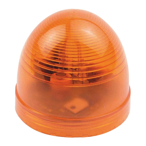
• Optical and acoustic telephone signalling device
• Protection category IP 66
• 4 different signalling tones
• Sound pressure approx. 95 dB(A) at 1 m
Operation
The weatherproof, optical and acoustic signalling device TWINKombi has been designed for use in general industrial
areas and allows for both indoor and outdoor operation.
Since 2002 the TWIN-Kombi can be connected to and operated with analogue telephone systems or any device with a
dry contact. In order
to ensure compatibility of the TWIN-Kombi with previous TWIN models, upon delivery the operation mode has been set
to connection with analogue telephone systems.
Note
Please read the User's Guide care - fully prior to installation of the device.
Any damage or claims are subject to the latest version of the "All - gemeine Lieferbedingungen für Erzeugnisse und
Leistungen der Elektroindustrie" (“General Terms of Delivery for Products and Services of the Electric Industry”).
Mounting
The TWIN-Kombi may be wallmounted. Make sure to mount the device in order to prevent dust and water from gathering
in the horn. This device must be installed at a height ≥2,5 m above the ground.
The fasteners and the mounting surface must be able to withstand the weight of the device (~0.9 kg).
Connecting and setting the operation mode
Only qualified technicians may connect and adjust the device.
Connecting:
Unscrew the flashlight hood from the base. The tensile strength reducer between the parts allows the flashlight hood to
hang freely. Insert the wires into the terminal room through the cable glands (fig. 1) and connect them according to the
marking.
Prevent damage to the wire from the hot parts of the connection by keeping the wiring short and direct.
Now you may change the settings - read more about this below.
Replace the lid, make sure the seal is clean and in good condition, and pull in the 2 screws slightly. Then tighten the
screws firmly until the lid is pressed against the base. Make sure the cable glands are securely fastened to the housing
and the cable. Follow the rules and regulations for connecting electrical devices to the 230 V power system.
When assembling the device, please pay attention to the "UP" ("OBEN") notes in the flashlight hood and the base. Both
notes must face in the same direction to ensure the device is assembled correctly.
Remove the information (depending on the version) supplied from inside the device, in order to avoid a possible fire
hazard.
Service
You have bought a modern product subject to strict quality control.
If any questions or malfunctions should occur – even after the guarantee has expired – please contact your FITRE
partner. Please have the product number (to be found on the nameplate) ready.

Care and maintenance
The TWIN-Kombi is maintenance free. Still, if the operating area is highly contaminated by dust, fat, oil etc., the device
should be cleaned from time to time.Use a moist cloth to dust off the device.
Warning! Never use sharp objects for cleaning. Do not use polishing or abrasive substances.
EMC-Directive
The device complies with the requirements of the new EMCdirective 2004/108/EC and the low voltage directive
2006/95/EC.
The conformity with the above directives is confirmed by the CE sign.
Setting the ringing sound pressure level
The ringing sound pressure level can be individually adjusted by means of the internal volume control (fig. 1).
Setting the operating mode
Use the jumpers (see arrow) to set the operating mode of the TWINKombi.
Fig. 2
Operating mode for connecting to the terminals W/Lb of analogue telephone systems
Fig. 3
Operating mode for connecting to devices with floating output.

Setting the ringing signal
Use the DIPswitch to set the ringing signal of the TWIN-Kombi.
Switch position] Tone sequence frequency [kHz Tone sequence [sec]
No. 1 No. 2 1.4 1.5 2.2 2.9
00XX 0.3
01 XX 0.3
10XX 0.5
11 XXX 0.2
Dimension illustration
Technical Data
Connection data:
Cable glands .........................................................M20 x 1.5 mm, clamping capacity ø 5-9 mm
Terminals...............................................................for strands up to 1.5 mm2
Mains connection:
Terminal designation.....................................L1, N, on the housing
Power supply ................................................230 VAC ±10% 50 Hz / 60 Hz
Operating time ..............................................TWIN-S has been designed for short-time or intermittent operation.
At 30°C ambient temperature and maximum power supply the
following conditions apply:
Duty cycle: ....................................................≤30 min.
Rest duration: ...............................................≥30 min.
Telephone connection:
Terminal designation.....................................W, Lb
Ringing alternating current............................24 VAC ... 75 VAC
Ringing frequency.........................................16 Hz ... 54 Hz
Overlaid supply voltage.................................0 VDC ... 63 VDC
Input impedance at 25 Hz.............................Z ≥8 kΩ
Input impedance at 50 Hz.............................Z ≥4 kΩ
Acoustic signalling:
Acoustic signalling device .....................................piezoelectric disc
Acoustic signal
(choose signal via DIP-switch) ..............................2-tone or multi-tone, 4 different settings
Sound pressure approx.........................................95 dB (A) at 1 m

Optical signalling:
Optical signalling device........................................flash tube W = 3 Ws
Flash frequency.....................................................2 Hz ... 5 Hz
Flash time following end of call
(bridging call pause)..............................................approx. 4s
Housing
Height x Width x Depth..........................................approx. 150 x 195 x 104 mm
Weight ...................................................................approx.0.9 kg
Operating position .................................................vertical wall mounting
Environmental conditions
Operating ambient temperature ............................-20°C ... +60°C
Transport and storage temperature.......................-20°C ... +85°C
Degree of protection according to IEC 60529 .......IP 66
Insulation class......................................................I
User information
This device is a weatherproof signalling device especially designed for use in rugged in dustrial conditions. Please note
the following warnings and security information:
1. The TWIN-Kombi 5843/5 was disigned in compliance with Insulation class I and may only be connected to and
operated at the voltage it was designed for. The device is not suited for continuous operation. Make sure the
connections are in perfect order. The connecting cable must be laid in a manner not to cause a tripping hazard.
2. The device may only be operated at the given ambient conditions (see also under "Technical data"). Adverse am
bient conditions, as for instance too high or too low ambient temperatures are not allowed, due to increased risk of
an electronic parts breakdown.
3. Make sure the device and the connecting cable(s) are not damaged. If the device is damaged, it may not be
operated.
4. While the device is in operation please follow all relevant legal and professional regulations, the legally required
precautions to be taken to prevent accidents, laws and regulations governing the connection of a device to private
branch exchanges and public telephone networks and the operation of such a device. Only a trained professional
may connect, take in use or maintain this device.
5. In case of repairs, use only original spare parts, which must be changed by trained and skilled personnel. Other
spare parts may cause damage.
6. Disconnect power before opening the device.
7. Take into consideration the required operating position.
8. Continuous use of the device and/or too short a distance between persons and the sound source may cause hearing
damage.
9. External protection devices
The telephone call repeater TWIN S need local power 230VAC for activating the bell and the lamp, the activation
command is made by the analogue telephone line ACB
9.1 Local power 230VAC
The TWIN S must be protected from eventual short circuits or overcharges by external devices, i.e. fuse and
electric switch, to be supplied and installed at installer care.
On the label there are the nominal and maximum absorption values
Nominal absorption: 100mA, 230VAC
Maximum absorption: 150mA, 230Vac
It is suggested a delay fuse 200mA and an electric switch 230VAC, 0.5A
9.2 Telephone activation circuit
The call repeater activation circuit is made by the bell line voltage generated by the telephone central
exchange.
A telephone line protection, i.e. FITRE PR164, must be installed at installer care.
10. This product is subject to technical improvements without prior notice.


Subject to alteration or errors
FITRE S.p.A. – telecomunicazioni & elettronica
20142 MILANO – ITALY – via Valsolda, 15
tel.: (+39) 02.8959.01 – fax: (+39) 02.8959.0400
Filiali ROMA e VENEZIA
7332951EN 1611
Table of contents
Popular Security System manuals by other brands

Texecom
Texecom Premier Elite Impaq Contact-W instruction manual

NAPCO
NAPCO Magnum Alert 1016e Quick Star User Guide

Hills
Hills VoiceNav user manual

NAPCO
NAPCO Magnum Alert 800 operating guide

EDWARDS SYSTEMS TECHNOLOGY
EDWARDS SYSTEMS TECHNOLOGY EST2 Operation manual

GE
GE AL-1291 Point ID installation manual
