FITWAY FW-1000IC User manual
USER MANUAL
FW-1000IC

Amendment: Console Pairing Instructions
Although your new FitWay 1000ic may come with the wireless console paired, it is sometimes possible that
the console will have to be paired with the bike again after assembly. Please follow the steps below to
complete the pairing process:
1) Remove the battery cover from the back of the console.
2) Start pedaling the bike to engage the sensor
3) While still pedaling have someone remove one of the batteries for 10-20 seconds and re install. It
is important to continue pedaling throughout the entire process.
4) Replace battery cover.
Your console should now be paired. If the console is still not reading correctly please repeat the above steps.
If you continue to experience connection issues, please contact us through the form at the following address:
https://fitwayequip.ca/pages/warranty

SAFETY GUIDELINES
Regular maintenance of the bike should be performed and is essential to keep your Indoor Cycle in
top operating condition. Without preventative maintenance, normal wear and tear may cause
cumulative effects, such as misalignment or early replacement of parts.
1. Once assembled, please inspect to make sure that all hardware parts such as bolts, nuts and washers
are positioned and tightened correctly.
2. Be sure to wear shoes when exercising and tighten the pedal cage and straps. When using SPD shoes,
make sure that the buckle is fully inserted. Do not remove your foot from the pedal when the flywheel is
spinning, and do not get off the bike until the flywheel, pedals and cranks stop moving completely.
3. We recommend lubricating all moving parts monthly with silicon lubricant.
4. Water bottle cages are easily damaged when over-sized bottles are forced to fit within them. Checking
and tightening the screws will help prevent damage, but never force a bottle into the holder as it could
lead to breakage.
5. Wipe down the bike at the end of each use. Consider using mildly alkaline cleaning or neutral cleaning
liquids, never use oil-based cleaning liquids when wiping down the bike, to avoid surface damage.
6. Please keep children away while riding. The bike is designed for adults and is not suitable for children.
7. If you have any pain or tightness in your chest, an irregular heartbeat, shortness of breath, feel faint or
have any discomfort while you exercise, STOP IMMEDIATELY, and seek medical assistance.
8. Do not place fingers or any other objects into moving parts of the Indoor Cycle. Do not wear loose
clothes while using this or any piece of fitness equipment.
9. Before starting any exercise program, consult with your physician first. He or she can help establish the
exercise frequency, time and intensity appropriate for your particular age and condition.
10. After exercising, please turn the adjustment control knob clockwise (+) to increase tension so the pedals
will not rotate freely and possibly hurt a passerby or the next user.
11. This Indoor Cycle has passed the standard test of EN 957-1:2005 and EN 957-10:2005, suitable for
home use. The max user weight should be within 120 kg.
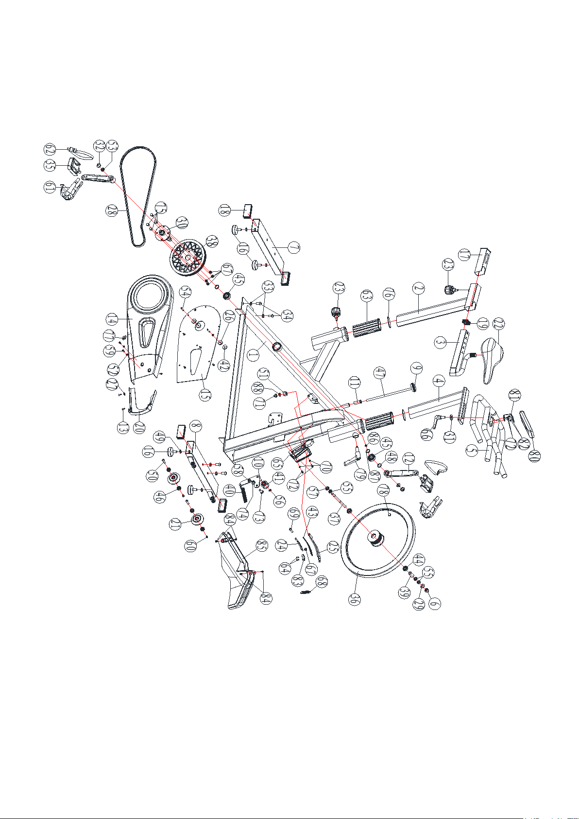
EXPLODED VIEW

PARTS LIST
NO. DESCRIPTION SPECIFICATION QTY
1 Main Frame 1
2 Seat Post 30*70*1.5T*340L 1
3 Seat Slider 38*38*270L*T1.5 1
4
Handlebar Post
30*70*1.5T*340L
1
5 Handlebar Ø28*2T 1
6 Cap Nut M12*P1.0 1
7 Rear Stabilizer 40*80*498*1.5T 1
8 Front Stabilizer 40*80*498*1.5T 1
9 Tension Knob M10 1
10 Tension Bracket welding 1
11 Plastic Sleeve Φ19*Φ15.5*40L 1
12 R/L Crank 9/16"-20UN 1SET
13 Phillips Self-Tapping Screw ST4.8*15 9
14 Chain Cover A 1
15 Chain Cover B 1
16 Base Leveler M10 4
17 Plastic Sheath-Inner Pipe(long)1
18 Stabilizer Cap 40*80*1.5T 4
19 Seat Slider Cap 38*38*1.5T 1
20 Front Cover 1
21 Pulley D8*D71.5*W223 2
22 Seat 1
23 Pop Pin M16*P1.5*15L 1
24 Magnet □25.4*6.4T 3
25 Brake Pad Holder 1
26 Plastic Mat-Chain Cover Ø25*Ø6.5*6T 2
27 Sheet Metal Screw Clip 1
28
Belt
5PK 1315mm
1
29 Flat Washer Φ12*2T 1
30 Axle Welding 1
31 Flat Washer(bigger and thicker)φ30*φ10.5*4T 1
32
Crank Cover
2
33 Flat Washer Φ20*Φ10*1.5 4
34 Button Hex Socket Head Screw M10*25L 4
35 Right&Left Pedal 9/16"-20UN-L/R 1SET
36 Flywheel 1
37 Flywheel Spindle M12*Ø15*P1.0*157L 1
38 PK belt wheel 1
39 Sleeve Ø20*Ø15.2*34L 1
40 Tension Spring Ø2.5*17 1
41 Pully Flywheel-Front Drive φ37*φ30*24.5 1
42 Rubber Washer Ø25*Ø8*2T 2

43 Magnet Plate 1
44 Bearing 6202 6202-2RS 2
45 Bearing 6004 6004-2RS 2
46 Bearing 608 608-ZZ 4
47 Brake Thread Rob Φ10*240L 1
48 C-Shaped Buckle Φ20 2
49 Hexagon Bolt M10*8T 4
50 Inner hexagon hollow bolt Φ8*M6*30 2
51 Brake Adjusting Nut 20*15L 1
52 Washer Φ5.2*1.0T 4
53 Inner Hexagon Flange Bolt M10*P1.25*8 2
54 Cross Recessed Countersunk Bolt M5*25L 2
55 Hexagon Thin Bolt M12*P1.0 3
56 C-Shaped Buckle Φ10 1
57 Hexagon Flange Bolt M12*P1.0 1
58 Nylon nut M10 1
59 Cross Recessed Pan Head Bolt M5*12L 2
60 Inner Hexagon Flat Round Head Bolt M6*12L 2
61 Pedal House 2
62 String-Pedal 2
63 Plastic Sheath-Inner Pipe 2
64 Cross Recessed Pan Head Bolt M5*12 2
65 Water Bottle Holder 1
66
Quick Handle
M10x25
1
67 Nylon nut M8 5
68 Brake tension spring 1
69 Inner Hexagon Flat Round Head Bolt M8*65 1
70 Washer φ16*φ6*2T 1
71 Cap Nut M10 1
72 Philips Screws M5*12L 4
73 Inner Hexagon Flat Round Head Bolt M10*25L 1
74 Washer Φ20*Φ10*1.5T 1
75 Outer Hexagon bolt M8*16 4
76 Inner Pipe Cap 30*70*1.5T 2
77 Wireless Sensor 1
78 Magnet 1
79 L-Quick Handle 1
80 Console 1
81 Console Mount 1
82 Philips Bolt M5*12 2
83 Brake Block 30*20*10T 1
84 Philips Bolt M5*10 6
85 Front Fender 1
86 Distance Ring Ø24*Ø20.4*5T 1
87 Wave Washer 1
88 Hexagon Nut M10*6T 1
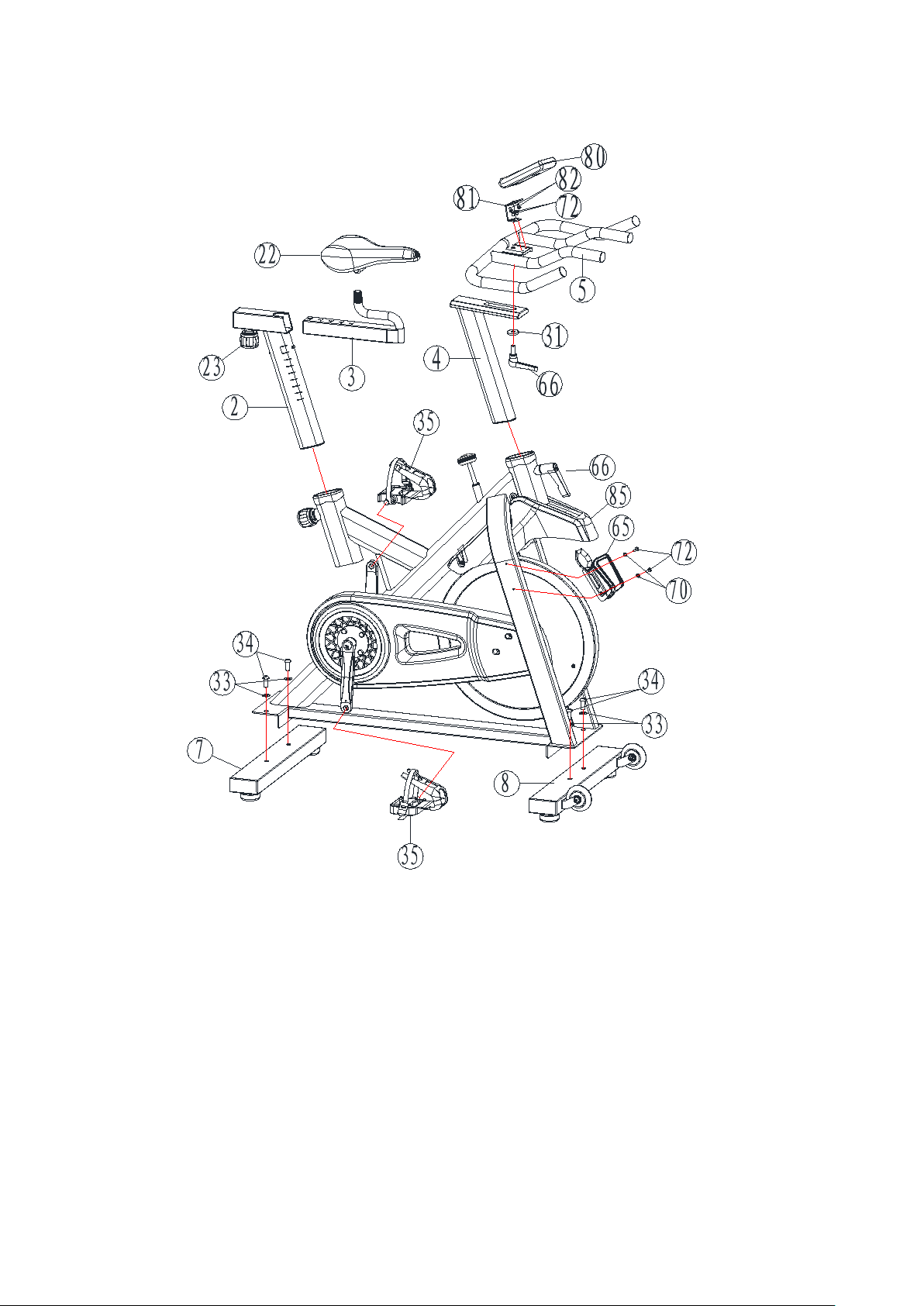
ASSEMBLY INSTRUCTIONS

STEP 1: Assemble Front and Rear Foot Tubes
Detach the shipping supports (metal pieces attached with 2 screws under the front and rear
stabilizers.) Discard the supports and screws.
Follow the figure below and attach the Front Stabilizer (8) and Rear Stabilizer (7) under the Main
Frame (1) with 4 pcs of Button Head Hex Socket Bolts (34), and 4 pcs of Flat Washer (33) by using
the supplied Allen wrench for fastening.
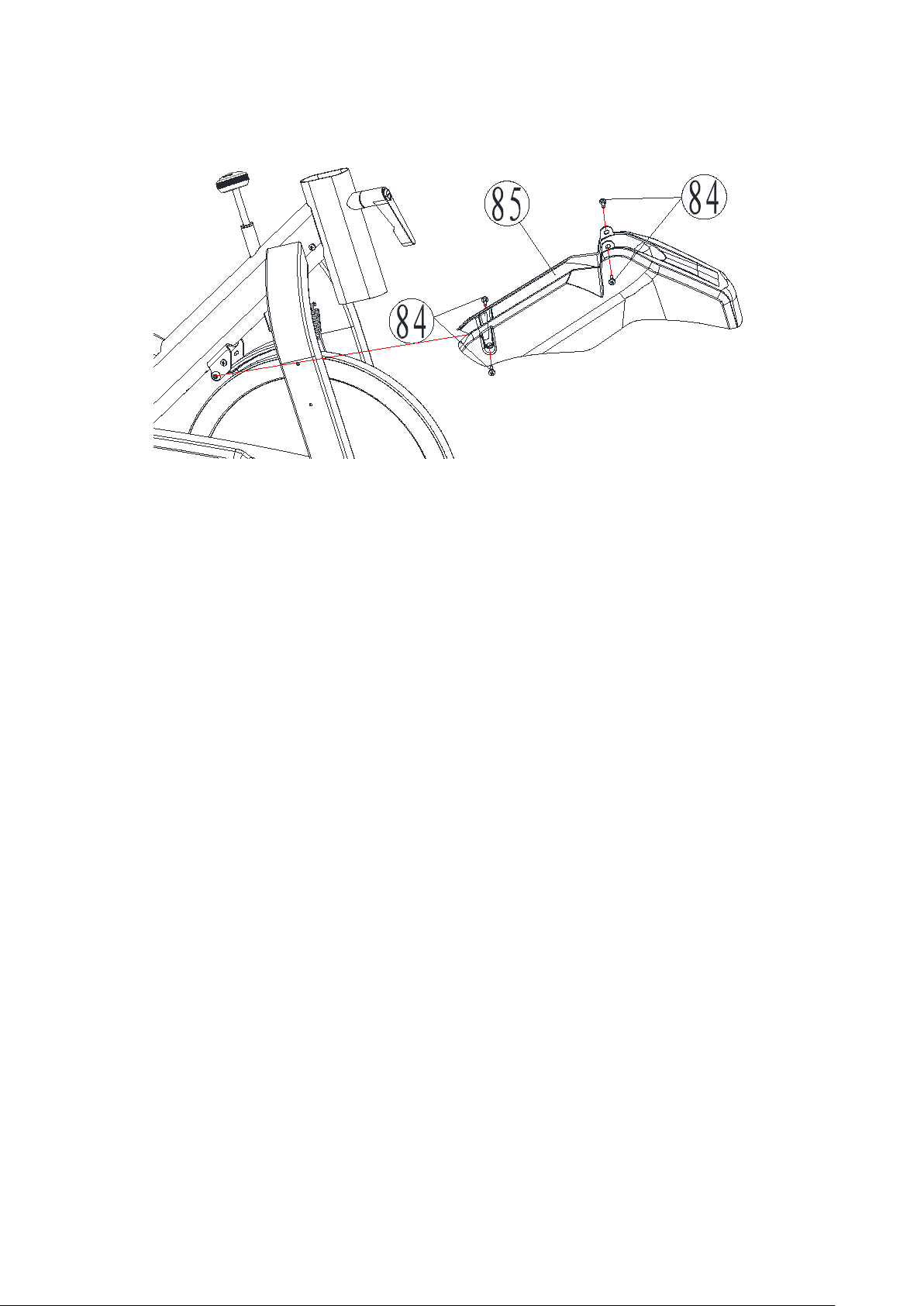
STEP 2: Assemble the Front Fender
Attach the Front Fender (85) to frame with Phillips Bolt (84).
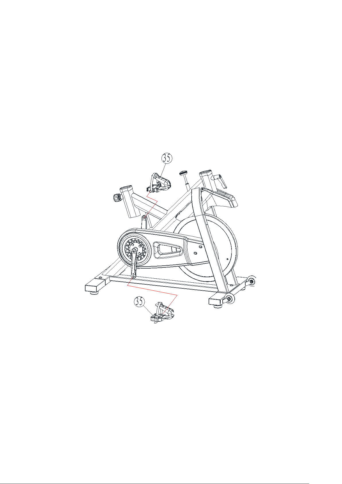
STEP 3: Install the Pedals
Gently insert the Left Pedal into the Left Crank, make sure the pedal is at a 90° Angle to the
crank. Slowly rotate the Left Pedal (35-L) into the left crank using Open Spanner Wrench (15)
towards the direction of Handlebar (counterclockwise). Note, the left side is designed with
reverse threading so the pedal will not come loose during use. Make sure the pedal is firmly
fixed.
Fix the Right Pedal (35-R) in the same with the same method. Make sure the rotate direction
of Left or Right Pedal should both toward the direction of Handlebar (clockwise).
Pay attention to ensure the correct pedals are used on the correct side otherwise you risk
damage to the pedals and cranks, and potentially could have the pedals fall off during
exercise.
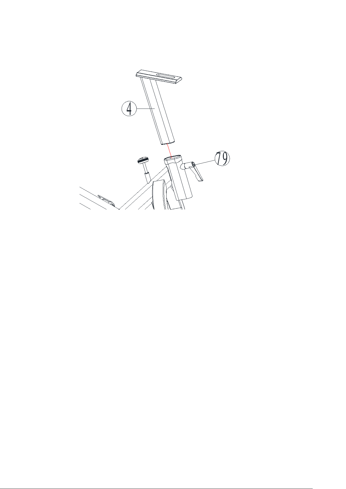
STEP 4: Assemble the Handlebar Post
Slide the Handlebar Post (4) into the housing on the Main Frame (1). Install and tighten the
L-Quick Handle (79) to secure the Handlebar Post. (As Pictured)

STEP 5: Assemble the Handlebar
Attach the Handlebar (5) to the Handlebar Post (4) and tighten in with the ratcheting Quick Handle
(66) and Flat Washer (big and thick) (31).
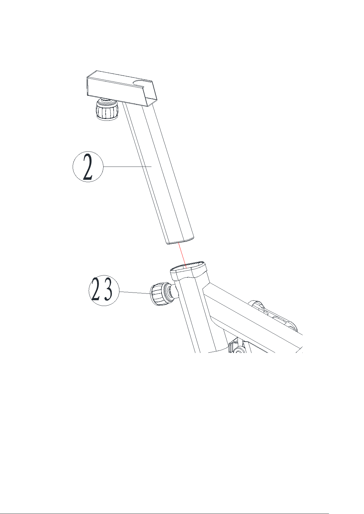
STEP 6: Assemble the Seat Post
Slide the Seat Post (2) into the housing on the Main Frame. Install and tighten the Quick Handle
(23) to secure the seat post.
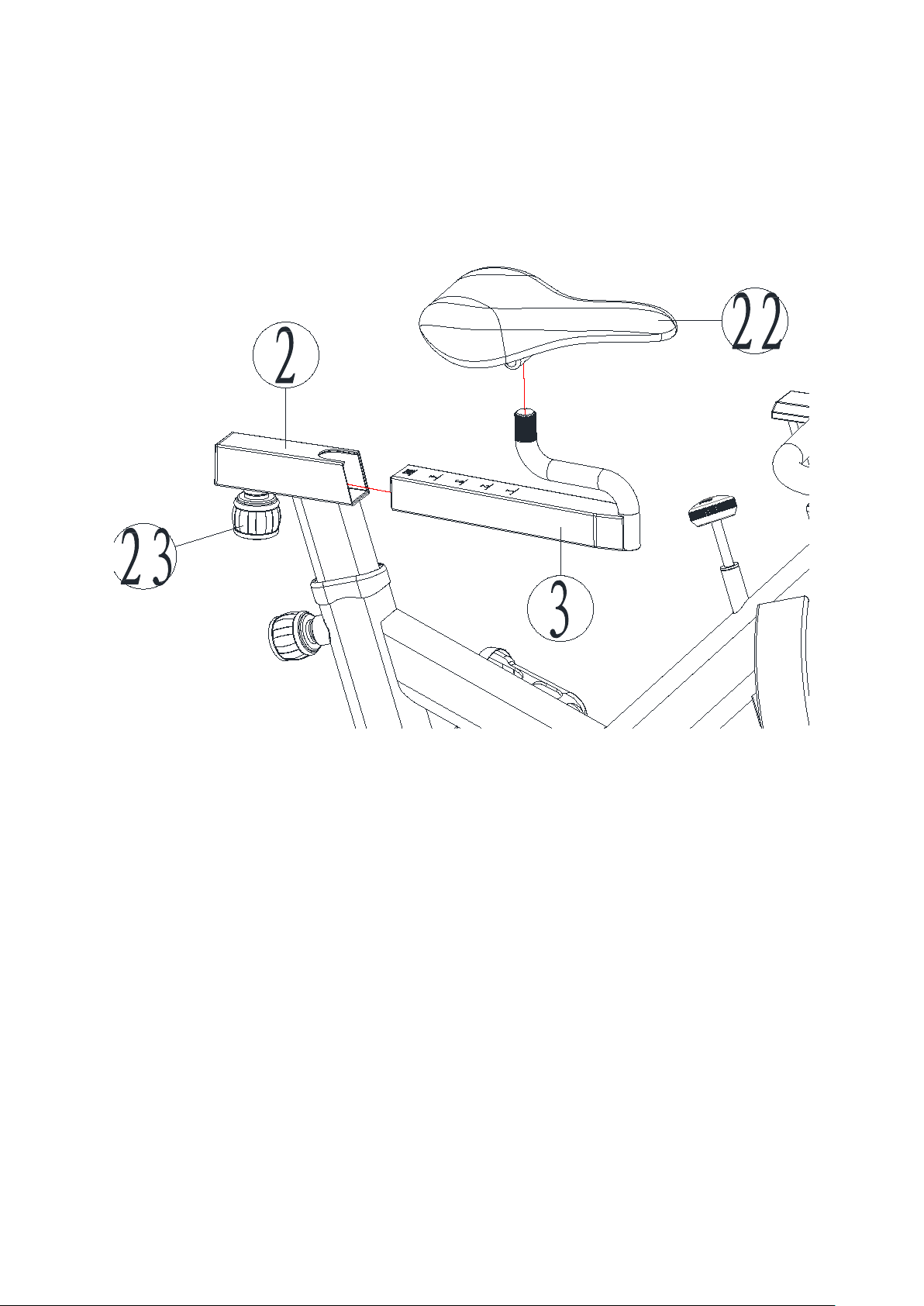
STEP 7: Assemble the Seat
Loosen the Pop Pin (23) and then pull down on the Pop Pin (23) to insert the Seat Slider (3) into the
Seat Post (2). Re-tighten the Pop Pin (23). Attach the Seat (22) to the Seat Slider (3) with the
wrench provided. Ensure tightness up/down as well as left/right and be sure to look for correct
positioning for your comfort.

STEP 8: Assemble the Console
Install the Console Mount (81) onto the handlebar (5) with Philips Screws (72). Install the
Computer (80) onto the Computer Mount (81) and then lock it with Philips Bolt (82).

STEP 9: Assemble the Water Bottle Holder
Install the water bottle holder (65) onto main frame with Washer (70) and Philips Screws (72).

SAFETY CHECK, TRANSPORT & MAINTENANCE
1. Before using your Indoor Cycle, please kindly check that all the moving parts (screws, nuts,
adjustment levers, etc.) are firmly tightened and secured. Please check your equipment regularly. If
any damaged parts are found, discontinue use, and replace them immediately. Do not exercise with
your Indoor Cycle until relevant worn parts are repaired or replaced.
2. Please pay special attention to the most easily worn parts such as belts, cranks, seats, etc.
3. Inspect the cranks and pedals before use, to ensure they are assembled and tightened correctly.
If not, please repeat the installation steps before use.
4. After each use, we advise to use furniture polish/wax or weak alkaline cleaner for routine
maintenance. At minimum we suggest wipe down the cycle with a soft, dry cloth.
5. To move the Indoor Cycle, stand in front of the bike, push down on the tips of the handlebars,
and tilt the bike forward onto the wheels. Then push or pull the bike to the desired location

COMPUTER OPERATION
BUTTONS (Left to Right):
MODE
-Select what appears in the window
-Hold for 2 seconds to reset all data
SET
-Set the values of the current display, hold to quickly increase
REST
-Resets the current values displayed on the screen
RECOVERY
-Press to enter or exit the pulse recovery function while in the Heart Rate Display mode
(only works when using a compatible heart rate strap, sold separately)
FUNCTION:
1. SPEED: Window A is shown
a) The current exercise speed is displayed
2. TIME: Window B is shown
a) Counts the cumulative time from exercise start to finish. Will automatically
stop if there is no activity for more than 6 seconds
b) Exercise time can be set, up to 99 minutes. Each press adds 1 minute, timer
counts down to zero. The TIME will flash and beep for 5 seconds when the
goal is reached.
3. DISTANCE: Window C is shown
a) Counts the cumulative distance from exercise Start to Finish. KM is
Kilometers, MI is Miles
b) Exercise distance can be set, up to 99 KM or MI, each press adds 0.1, distance
counts down to zero. The DIST will flash and beep for 5 seconds when the
goal is reached.
4. CALORIES
a) Counts the cumulative calories consumed from exercise Start to Finish.
b) Target Calories Burned can be set up to 999, each press adds 1, and counts
down to zero. The CAL will flash and beep for 5 seconds when the goal is
reached.
5. PULSE: Window E is shown
a) Shows your current heart rate during exercise when using an optional Polar
Compatible Chest Strap (sold separately)
b) Pulse Range 40-220 BPM
6. AUTO OFF
a) Computer automatically shuts off when there is no activity for more than 45
minutes
b) Data will be saved

CONGRATULATIONS
Thank you again and congratulations on your purchase of this FitWay Indoor Cycle. Should you
have any questions or concerns please contact us at:
Support@fitwayequip.com
Full Warranty details can be obtained at:
fitwayequip.com
-or-
By emailing us at: Support@fitwayequip.com
Enjoy your new Indoor Cycle
Table of contents


