FIVE OCEANS PACIFIC WINDLASS Series User manual
PACIFIC
WINDLASS SERIES
OWNER MANUAL
600| 900|1000 | 1500 MOTORS
SAVE THESE INSTRUCTIONS
Important safety instrucons
are included in this manual.

TABLE OF CONTENTS
Introduction
Specications
Protection Notice
Fitting
Electrical
Installation
Basic Requirements
Accessories
Fitting the Windlass to the Deck
Electrical Wiring
Electric Cable Selection
Wiring
Control Switch Installation
Wiring Diagram
Operation
Manual Control
Power Down/Up
Windlass Operating Procedures
Servicing
Servicing Schedule
Troubleshooting
Warranty
Product Guide
3
3
6
7
7
7
7
8
8
10
10
10
10
11
13
13
13
14
16
16
16
17
19

3
FIVE OCEANS PACIFIC SERIES
1- Introduction
Thank you for choosing Five Oceans. Five Oceans products are world
renowned for their quality, technical innovaon and proven performance.
With a Five Oceans product you will be provided with many years of out-
standing service.
Product Support
Five Oceans products are supported by a network of distributors and Au-
thorized Service Representaves. If you encounter any dicules with this
product, please contact your naonal distributor, or your local Five Oceans
dealer. Details are available at: www.ve-oceans.com.
Important informaon about this manual
Throughout this manual, you will see safety and product damage warnings.
You must follow these warnings carefully to avoid possible injury or damage.
Pacic 600
2 - Specications
1/2"(12mm)
1/2"(12mm)
8.73
8.73
D (mm) D (in) P (in) W (in)P (mm) W (mm)
0.343
0.343
0.330
0.390
25.4
25.4
1.000
1.000
30.1
30.1
1.19
1.19
8.38
9.91
26.2
31.0
1.030
1.22
29.5
34.8
1.16
1.37
1/4" HT G4
1/4" HT G4
9/16" (14mm)
5/8"(15mm)
5/16" HT G4
3/8" HT G4
Pacic 900
Pacic 1000
Pacic 1500
D
P
W

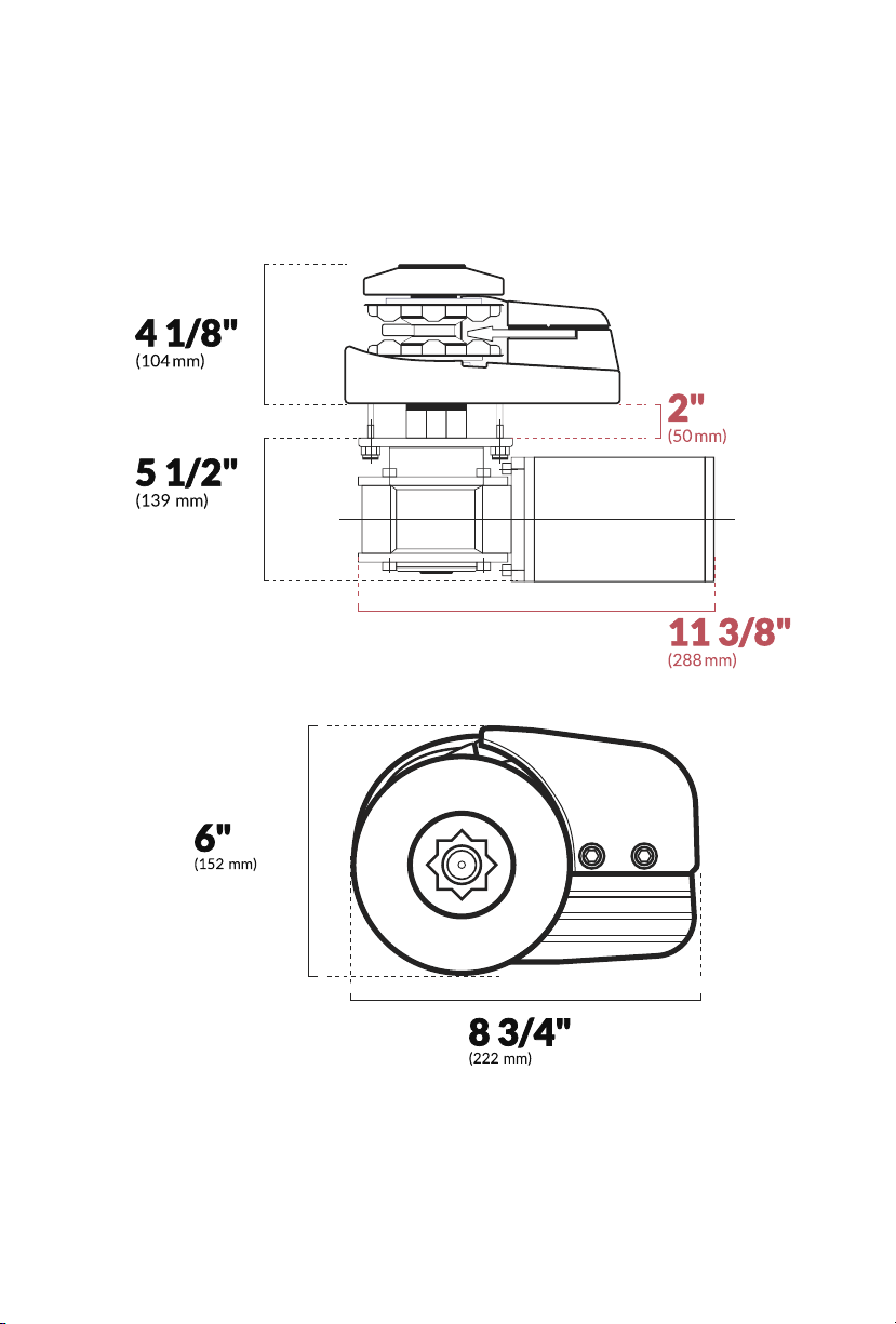
4VERTICAL WINDLASS MANUAL VOLUME ONE
Pacic 600
Pacic 600 & Pacic 900
Electric Specications
Dimensions Diagram
12
12
12
12
Pacic 900
Pacic 1000
Pacic 1500
MODEL
MOTOR
Voltage Wa
600
900
1000
1500
450
657
750
1200
990
1450
1650
2640
kg lb
MAXIMUM
PULL
26
40
40
40
m/min. /min.
DROP SPEED
85
131
131
131
150
220
250
485
330
484
550
1067
kg lb
WORKING
LOAD LIMIT
33
55
60
95
Amp
NORMAL
CURRENT
DRAW
MAX
5
FIVE OCEANS PACIFIC SERIES
Pacic 1000 & Pacic 1500
MAX

6VERTICAL WINDLASS MANUAL VOLUME ONE
3- Protection Notice
At all mes it is the responsibility of the boat user to ensure that the anchor and rode are
properly stowed for the prevailing sea condions. This is parcularly important with high-speed
powerboats, because an anchor accidentally deploying while under way can cause considerable
damage. An anchor windlass is mounted in the most exposed posion on a vessel and is thus
subject to severe atmospheric aack resulng in a possibility of corrosion in excess of that
experienced with most other items of deck equipment. As the windlass may only be used
infrequently, the risk of corrosion is further increased. It is essenal that the windlass is
regularly examined, operated and given any necessary maintenance.
Please ensure that you thoroughly understand the operaon and safety requirements of the
windlass before commencing the installaon. Only persons who are completely familiar with
the controls and those who have been fully made aware of the correct use of the windlass
should be allowed to use it. If there is any doubt of how to install or operate this unit please
seek advice from a suitably qualied engineer.
• Windlasses used incorrectly could cause harm to equipment or crew.
• Windlasses should be used with care and treated with respect.
• Boang, like many other acvies can be hazardous. Even the correct selecon, mainte-
nance and
• use of proper equipment cannot eliminate the potenal for danger, serious injury or
death.
• Five Oceans windlasses are designed and supplied for anchor control in marine applica-
ons and are not to be used in conjuncon with any other use.
• Keep limbs, ngers, clothing and hair clear of windlass and anchor rope/chain and anchor
during operaon. Severe bodily harm would result.
• Ensure there are no swimmers or divers nearby when dropping anchor.
• When the Windlass is not in use the anchor must be ed o onto a cleat or equivalent
strong point to prevent damage to the boat.
• Windlass must not be used as the sole means of securing the anchor to the bow ng
especially under storm condions. Anchors should be independently secured to prevent
accidental release.
• Classicaon Sociees require that a vessel lying at anchor must have its anchor rope/
chain secured to a chain stopper or other suitable independent strong point.
• A windlass should never be used as a mooring bollard, the anchor rode MUST be secured
to a mooring cleat, chain stopper or other designated strong point. Using the windlass to
secure the rode will damage the windlass.
• Do not use windlass for ANY purpose other than deployment and recovery of anchor.
• Do not wrap chain around a capstan barrel or drum where ed.
• A circuit breaker/isolator should always be used with this windlass to protect the motor
and cables from overheang and damage.
• Always switch o this windlass at the circuit breaker/isolator when not in use.
• It is the unavoidable responsibility of the owner or master or other responsible party to
assess the risk of any operaon on the vessel.
• Windlass must not be operated whilst under the inuence of alcohol or drugs.
7
FIVE OCEANS PACIFIC SERIES
3.2 Fitting
• This equipment must be installed and operated in accordance with the instrucons con-
tained in this manual. Failure to do so could result in poor product performance, personal
injury and/or damage to your boat.
• Consult the boat manufacturer if you have any doubt about the strength or suitability of
the mounng locaon.
3.3 Electrical
• Make sure you have switched o the power before you start installing this product.
• This product requires installaon by a suitably qualied electrical engineer.
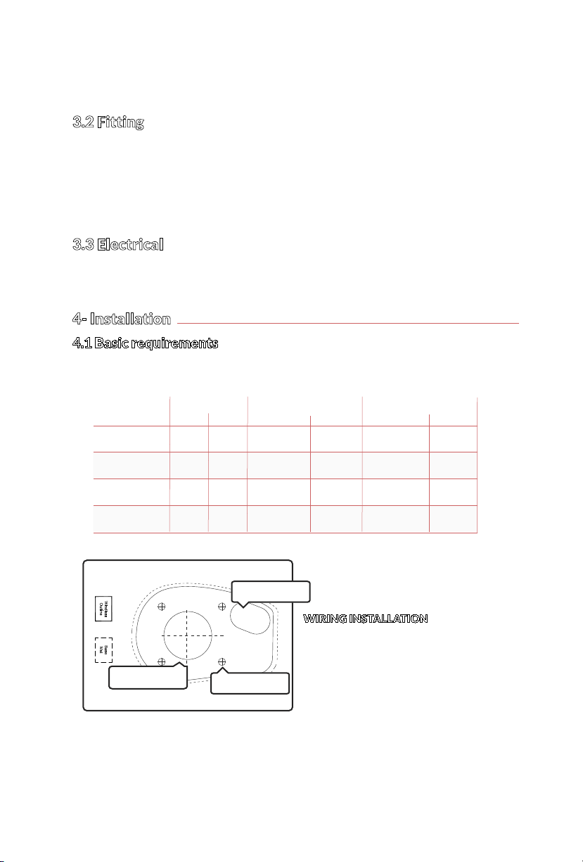
4- Installation
4.1 Basic requirements
Each installaon requires the following tools: Windlass Installaon
WIRING INSTALLATION
• Crimping Pliers / Wire Stripper
• Suitable electrical cable and crimp
terminals
Pacic 600 5/16"
5/16"
5/16"
5/16"
Pacic 900
Pacic 1000
Pacic 1500
MODEL
DRILL
in mm
8
8
8
8
1 11/16"
1 11/16"
2 9/16"
2 9/16"
2 3/32"
2 3/32"
2 3/32"
2 13/32"
44
44
52
61
in mm
HOLE SAW SM
in mm
HOLE SAW LG
52
52
65
65
DRILL HOLE
HOLE SAW SM
HOLE SAW LG

8VERTICAL WINDLASS MANUAL VOLUME ONE
2. Place the windlass on the deck and decide
upon a posion for it with reference to
the vessel’s bow roller (Fig. 4.3-2) and the
chain locker below. Rode lead from the
roller should ideally be fed horizontally
back to the top of the gypsy and along
its centerline (Fig. 4.3-3). There must be
sucient vercal fall for the chain or rope,
even with a full locker, to draw the rode
from the gypsy when hauling in.
3. Place the mounng template on the deck
or mounng pad in the desired posion
for the windlass and hold it in place using
adhesive tape.
NOTE: Check the scale of the template
matches the winch.
12" (300 mm)
4.3-2
4.3-3
4.2 Accessories
Use only genuine Five Oceans parts and accessories to ensure top performance and eliminate
the risk of voiding your warranty. For replacement parts, please visit your dealer or
www.ve-oceans.com
4.3 Fitting The Windlass to the Deck
1. If the deck is not at, a suitable mounng
pad may be required to take up camber or
sheer. Decks that are thin, or of foam or
balsa laminate construcon, will require
reinforcement in order to spread the
loads that will be applied to the deck
while the windlass is in use. The standard
5/16" (8 mm) threaded mounng studs
supplied suit deck and packing
thickness of up to 1 1/4"(35 mm) for
Pacic 600/900 and up to 2" (50 mm) for
Pacic 1000/1500. These are adequate for
most installaons.
4.3-1

9
FIVE OCEANS PACIFIC SERIES
4. Using a 5/16"(8mm) diameter drill, make the
four (4) holes for the mounng studs. With a
2 1/2” (44 mm) diameter hole saw, make the
hole for the rode to pass throughwith a 4 1/2”
(52 mm) diameter hole saw, make a hole for
the motor gearbox to pass through. When
all the holes have been made, remove the
template. To help avoid water absorpon by
the deck, apply an appropriate marine sealant
to the freshly cut hole edges.
5. Fully screw the four (4) mounng studs into the base
of the windlass. Screw the studs into the base nger
ght, with the ats towards the base as shown
(Fig 4.3-5).
6. Next, ghten the studs unl they boom out in their
holes. Do this to each of the studs in turn.
Pass all the studs through the
deck and t them security on
the motor piece which is on
the underside of the deck and
secure the unit with the xings
provided.
7. Place the base mat in posion on the deck, oponally, apply a suitable sea ant to the base
of the windlass, any mounng pad or around the studs.
NOTE: If using silicone or other rubbery type sealant, it is advisable to allow curing of the
sealant before nal ghtening of the mounng nuts.Trim the studs back to 6 mm (1/4”)
below the fully ghtened nuts.
4.3-4
4.3-5

10 VERTICAL WINDLASS MANUAL VOLUME ONE
5.2 Wiring
Plan the installaon to suit the controls and give the operator a full view of the windlass. The
wiring system should be of the fully insulated type, which avoids possible electrolyc corrosion
problems.
We recommend the use of type III stranded, nned copper wire with copper crimp
terminals (NOTE: we recommend that the cable are shorter if possible.). Most modern installa-
ons are negave return (negave ground) but polarity should be checked. Overload protec-
on, in the form of the circuit breaker provided must be built into the windlass wiring circuit.
• Circuit breaker supplied:
Pacic 600 Series (Circuit Breaker: 60 Amps - 80 Amps)
Pacic 900 Series (Circuit Breaker: 80 Amps)
Pacic 1000 Series (Circuit Breaker: 100 Amps)
Pacic 1500 Series (Circuit Breaker: 135 Amps)
• The circuit breaker should be posioned close to the baery in a dry, readily accessible place.
• The breaker must be manually reset should an overload occur that causes it to trip to the o
posion.
Warning
If you are not sure you understand these guidelines, seek professional help. Ensure that the
installaon complies with USCG, ABYC, NMMA or other local regulaons.
5.3 Control switch installation
The unit is supplied with
Visit www.ve-oceans.com for more informaon
Contactor box (should be located within an dry area) and control box used in some installaon
refer to wiring diagram S 5.4
5- Electrical wiring
5.1 Electric cable selection
Five Oceans recommends the installer source and install cable that meets the requirements of
the standards and regulaons relevant to the installaon and codes of pracce.
The cable table gives recommended cable sizes based on total length of cable required, from
the baery, following the route of the cables.
CABLE SIZING FOR LENGTH OF CABLE RUN
Windlass performance is directly related to cable size and length. Voltage drop over the
complete wiring run must not exceed 10%.
Pacic 600 6 AWG (16 mm²) 2 AWG (25 mm²)
Pacic 900
Pacic 1000
Pacic 1500
2 AWG (25 mm²)
2 AWG (25 mm²)
1 AWG (35 mm²)
1 AWG (35 mm²)
1 AWG (35 mm²)
0 AWG (50 mm²)
MODEL up to 24 (up to 8 m) 24 - 50 (8 - 16 m)
DO NOT confuse cable length
with the length of the vessel

11
FIVE OCEANS PACIFIC SERIES
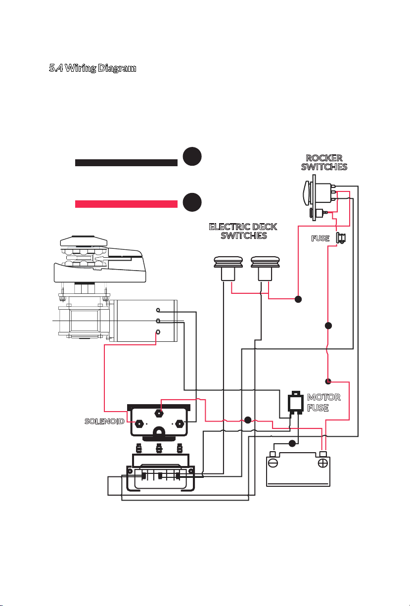
5.4 Wiring Diagram
Positive Wire
Negative Wire
MOTOR
FUSE
FUSE
ELECTRIC DECK
Main Switch
SWITCHES
ROCKER
SWITCHES
SOLENOID
top view
Foot Up Foot Down
side view
A2A1
M1 M2
C
Battery
12 VDC
2
2
2
1
1
1
Pacic 600 & Pacic 900
12 VERTICAL WINDLASS MANUAL VOLUME ONE
Positive Wire
Negative Wire
MOTOR
FUSE
FUSE
ELECTRIC DECK
Main Switch
SWITCHES
ROCKER
SWITCHES
SOLENOID
top view
Foot Up Foot Down
side view
A2A1
M1 M2
C
Battery
12 VDC
2
2
2
1
1
2
2
Pacic 1000 & Pacic 1500
5.4 Wiring Diagram
13
FIVE OCEANS PACIFIC SERIES
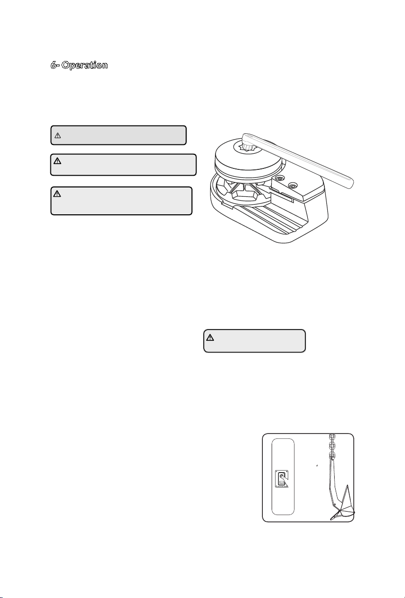
6- Operation
6.1 Manual Control
Use this method for quicker anchor deployment, in an emergency involving loss of power or to
save baery power. Observe marime anchor deployment safety rules.
6.2 Power Down/Up
1. Turn o all power to motor windlass and release any anchor locks.
2. When safe insert the Five Oceans wrench in to the capstan drive cap. Rotate clockwise to
grip the gypsy and anclockwise to free the gypsy controlling the rate of descent of the
anchor. Once deployed adjust desired scope if using a rope/chain, lock the clutch by turn-
ing the drive cap clockwise and engage the anchor locks. Remove the wrench handle.
To release anchor:
1. Check unit is not in manual mode.
2. Release any anchor locks.
3. Engage the circuit breaker/isolator.
4. Press down buon connuously unl you’ve reached the necessary length of chain/
rope.
5. Disengage the circuit breaker/isolator.
6. Lock anchor locks.
To retrive anchor:
1. Release any anchor locks
2. Engage the circuit breaker/isolator.
3. Press the UP buon connuously to retrieve the anchor.
4. Disengage the circuit breaker/isolator.
5. Lock anchor locks.
WARNING! Isolate (Turn off) the
windlass using circuit breaker / isolator.
WARNING! Trapping, crushing or
entanglement danger whiIst operating
windlass manually or under power
WARNING! Always remove
wrench handle aer use.
DONT FORGET
Always remove the handle aer use.

14 VERTICAL WINDLASS MANUAL VOLUME ONE
This is an anchor recovery device. DO NOT use the windlass to pull the boat to the anchor as it
will damage the mechanism. Vessels at anchor will snub on the rode and this can cause slippage
or apply excessive loads to the windlass. Best pracce is to use a bollard or other strong point
when at anchor and use the vessels engines to break the anchor free. Otherwise excessive load
will cause the freefall funcon to seize and can cause damage to the gearbox.
When anchoring, power rode out allowing the vessel to take up stern away prevenng the rode
tangling with anchor. Use this method for mooring stern rst to a jey. To aid recovery, under
power, move vessel towards anchor but not over and beyond, as this can cause damage to
topside. As anchor approaches the vessel use careful adjustments of controls to avoid damaging
vessel, start and stop the windlass to bring the anchor slowly into the bow roller. Pulling the last
bit of rode and anchor into the bow roller at full speed can damage the boat, bow roller and
windlass. When stowing it is important to make sure, parcularly with rode lines that there is at
least 300mm (12”) of free space below the windlass (See §4.5). Stop and check during the
stowing process to determine if there is sucient space on you vessel. If the rode pile is too
close to the underside of the windlass, re-distribute the rode away from directly below the
windlass. If the rode gets too close to the underside of the windlass it will cause problems with
good rode recovery and may cause damage to the line.
6.2 Windlass Operang Procedures
When retrieving anchor do not
overload or stall in windlass.
The rode should be secured directly to a bollard, sampson
post or cleat and a chain secured by a chain stopper.

15
FIVE OCEANS PACIFIC SERIES
• With whipping twine or similar, seize your rope
8" (200 mm) from the rope’s end and unlay the
strands.
• Pass one strand through the chain link from one side
and the other two strands from the opposite side.
Remove seizing and complete a back splice in the
normal manner for four full tucks.
• With a hot knife pare down the three strands by one
half of their diameter and connue with two further
tucks.
• With a hot knife, carefully melt the ends back into
the line. Because of wide variaons in rope type
and construcon some experimentaon may be
required.
• Whip the line with permanent whipping at the
beginning of the taper.
• The method of joining illustrated is designed to
minimize chafe between the rope and chain but as
a maer of prudent seamanship the splice should
be checked regularly and remade if there is any
evidence of wear.
6.3 Joining Rope to Chain
When splicing rope to chain, select a length of chain that will avoid having the splice posioned
in the gypsy when the anchor comes over the stemhead. Furthermore, ensure that the splice is
no ghter than the rope.
A hard splice is not desired.

16 VERTICAL WINDLASS MANUAL VOLUME ONE
8 Troubleshoong
1. Anchor falls down independently while windlass is not in use.
• This problem is a result of not securing the anchor rode combined with the gypsy drive
cap being slack. Tighten the gypsy drive cap using the Five Oceans wrench and always
secure the anchor rode independently of the windlass when not in use.
2. Failure to operate or sluggish operaon.
• The majority of these problems are electrical in nature. It is essenal that the proper
voltage be maintained. The proper voltage on a 12 Volt system is 13.5 Volts, constant low
voltage will damage motor.
• Ensure electrical cable size is large enough to handle the current draw and keep voltage
drop within acceptable limits (maximum 10%).
• Check control switches, connecons, baery condion, isolator switch, fuse and motor
for operaon failure.
3. Failure to operate.
• Is there a voltage at the input terminals to the contactor and switches. Check the circuit
breaker/ isolator switch and any fuses.
• Operate the switch. Is there voltage at the posive switch terminal on the solenoid. If
not, the switch (or its wiring), is difecve.
• Keep the switch acvated. Is there voltage at the main output terminal on the contactor.
If not check the contactor coil ground circuit. If okay, replace the contactor.
• Check the voltage at the motor. If voltage of at least 12.5 volts is present and the motor
does not operate, the motor is defecve.
7.1 Servicing Schedule
The service period is determined by the frequency of use. Professional user will need to carry
out these operaons more oen than the weekend user. Before commencing any work on this
or any other electrical product, isolate from the power source.
Bedding in period:
When new there are some areas that will need frequent checking. If no movement is found
they can be inspected less oen.
• Examine all electrical connecons, to make sure they are sound and corrosion hasn’t set
in. Tighten if necessary and protect if required.
• Check mounng studs are rmly clamped and ghten if required.
Aer use:
• Wash down the windlass using fresh water.
• Ensure rode is at least 12” (300mm) below the windlass
• Check anchor locker drain
• Check rode and splice for wear.
Annually or more oen if frequent user:
• Examine all electrical connecons, to make sure they are sound and corrosion hasn’t set
in. Tighten if necessary and protect if required.
• Check mounng studs are rmly clamped and ghten if required.
• Check rode and splice for wear.
• Check gypsy as it is a high wear item
7- Servicing
WARNING! Isolate the windlass
using circuit breaker/isolator
WARNING! Ensure rode is adequately
secured to an independent strong point

17
FIVE OCEANS PACIFIC SERIES
9 - Warranty
All Five Oceans® products sold by Baron USA, LLC or any of the product resellers is war-
ranted to be free from defects in material and workmanship from date of purchase.
1. PRODUCT: Windlass Series (Altanc & Pacic)
2. WARRANTY PERIOD:
Exclusive ve (5) Windlass Series Warranty from purchase date
◦1 year warranty: motor+gear box, electrical component including solenoid, switch panel, foot switch,
circuit breaker.
◦5 year warranty: product housing
3. CONDITIONS AND LIMITATIONS:
a. This warranty only applies to the original Buyer and it is not transferable.
b. Proof of purchase is required for warranty service. If a product purchased in the
USA. Please register within ninety (90) days from the date of purchase. Simply
complete registraon by including a copy of the purchase receipt as proof of
original purchase. All Buyer must register their product purchased directly at
Five-Oceans.com within the USA territory at
hps:www.ve-oceans.com/pages/register.
c. The warranty shall be limited to the repair or replacement of any parts of the
product which are defecve in materials or workmanship.
d. Responsibility for the selecon of products appropriate for the use intended by the
Buyer shall rest solely with the Buyer.
e. This warranty does not cover any incidental costs, incurred for the invesgaon,
removal, carriage, transport or installaon of the product.
f. A unit provided as an exchange or replacement parts will be subject to the warranty
of the original unit. The length of the warranty governing the exchanged unit will
remain calculated by reference to the purchase date of the original unit.
4. WARRANTY EXCLUSIONS:
This warranty does not cover the following:
a. Normal wear: Products with mechanical and electrical components need periodic
parts and service to perform well. This warranty does not cover repair when normal
use has exhausted the life of a part or the equipment as a whole.
b. Environmental condions, including but not limited to extreme temperatures, etc.
c. Normal maintenance is not covered by this warranty.
d. Failures due to acts of God and other force majeure events beyond the manufactur-
er’s control.
Other Exclusions - This warranty excludes:
◦ Cosmec defects such as paint, decals, etc.
◦ Corrosion & Normal Wear and tear of items such as winch cable, chains, hooks,
power/electric cables, etc.
◦Accessory parts such as storage covers.

18 VERTICAL WINDLASS MANUAL VOLUME ONE
5. VOIDING OF THE WARRANTY:
This warranty under the following
circumstances:
a. Use of a product in an applicaon for which it was not designed or intended;
b. Failure to service or maintain the product in accordance with the manufacturer’s
recommendaons;
c. Faulty or decient installaon of the product
d. Any modicaon or alteraon of the product;
e. Condions that exceed the product’s designed capacity, performance,
specicaons or safe working loads.
f. This warranty will not apply if the product is deemed to have been misused,
abused, neglected, involved in an accident, abused, used/loaded beyond the prod-
uct’s limits, modied, installed improperly or connected incorrectly to any electrical
component.
g. Use of parts that are not original Five Oceans
6. LIMITS OF IMPLIED WARRANTY AND CONSEQUENTIAL DAMAGE:
a. Baron USA, LLC or any of the product resellers disclaims any obligaon to cover any
loss of me, use of this product, freight, or any incidental or consequenal claim by
anyone from using this product.
b. THIS WARRANTY IS IN LIEU OF ALL OTHER WARRANTIES, EXPRESS OR IMPLIED,
INCLUDING WARRANTIES OF MERCHANTABILITY OR FITNESS FOR A PARTICULAR
PURPOSE.
c. Baron USA, LLC or any of the product resellers will not be liable for death, injuries
to persons or property or for incidental, conngent, special or consequenal
damages, loss or expense arising in connecon with the use or inability whatever,
regardless of whether damage, loss or expense results from any act or failure to act
by Baron USA, LLC or any of the product resellers, whether negligent or willful, or
from any other reason.
CONTACT INFORMATION
Five Oceans
Customer Service
11200 NW 107th St Suite 6-B, Miami, FL 33178 USA
Mon – Fri 10:00 AM – 2:00 PM (EST)
Phone Number: +1 305.640.8678
info@ve-oceans.com | www.ve-oceans.com
Technical Service
Mon – Fri 10:00 AM – 12:00 PM (EST)
Phone Number:+1 305.640.8678
info@ve-oceans.com
Inquiries outside the United States, please view our dealer page for the region which
pertains to you.

19
FIVE OCEANS PACIFIC SERIES
10 - Product Guide
Pacic 600 Vercal Windlass (Product Number: 3931) For more info click here.
Pacic 900 Vercal Windlass (Product Number: 3287) For more info click here.
Pacic 1000 Vercal Windlass (Product Number: 3288) For more info click here.
Pacic 1500 Vercal Windlass (Product Number: 3444) For more info click here.
Package Include (one (1) circuit breaker per windlass)
• Rocker Switch Panel w/Main Switch (Product Number: 3290)
For more info click here.
• Circuit Breaker 60 Amp (Product Number: 3295) For more info click here.
• Circuit Breaker 80 Amp (Product Number: 3294) For more info click here.
• Dual Direcon Solenoid (Product Number: 3292) For more info click here.
• Foot Switch (Product Number: 3291) For more info click here.
Not Included in Package (examples)
• Stainless Steel Chain Stopper (Product Number: 75) For more info click here.
• Stainless Steel Chain Stopper (Product Number: 2990) For more info click here.
• Anchor Roller | 11" (Product Number: 72) For more info click here.
• Stainless Steel Self-Lauch Anchor Roller (Product Number: 3696)
For more info click here.
• Stainless Steel Hinged Anchor Roller (Product Number: 4184)
For more info click here.

www.ve-oceans.com
VOLUME ONE
© Copyright 2019 Baron USA, LLC All rights reserved
This manual suits for next models
7
Table of contents
Popular Winch manuals by other brands

Kolpin Outdoors
Kolpin Outdoors KAWASAKI MULE QUICK-MOUNT 4500 Assembly & owners manual

Kong
Kong ORTLES Maintenance and operating instructions

WARRIOR
WARRIOR 80ENS24 Assembly & operating instructions

Fidlock
Fidlock WINCH Assembly guide

Ronstan
Ronstan Andersen Compact Motor 68ST product manual

BRADEN
BRADEN CH SERIES Installation maintenance and service manual


