FiveFish Studios PSU-2448mk2 User manual

PSU-2448mk2 Power Supply Kit
Regulated Split Power Supply
With +48V Phantom Power + Protection Fuses
Simplicity Counts, Detail Matters.
No part of this document may be reproduced, either mechanically or electronically, posted online on the Internet, in whole or in
part, without the expressed, written permission of FiveFish Studios. This document is solely provided
to the kit builder of the PSU-2448mk2 Power Supply Kit.

PSU-2448mk2 Power Supply Kit
Copyright ©2010 FiveFish Studios
www.fivefishstudios.com
Last Update: 7/08/10
Page 2

PSU-2448mk2 Power Supply Kit
PSU-2448mk2 KIT
Power Supply for Mic Preamps
and other OpAmp, InstAmp based projects
Assembly Guide Rev 4.2
This is a split power supply designed to give positive and negative voltages and +48V phantom power. It has a small form factor,
measuring only 2 inches x 5 inches x 1-1/8” inch tall.
The Printed Circuit Board is professionally manufactured, with double-sided copper, plated-through holes, and top silkscreen
component labels.
This Power Supply is designed to work with the SC-1, SC-1mk3, X-12 Mic Preamp Kit, or any other opamp/preamp project
requiring a split power supply.
Each voltage rail output is continuously adjustable via it’s own trimmer. The V+ and V- outputs can be adjusted for +/-15,
+/-16, +/-18, +/-24V projects…. Or any voltage you want.
The 48V DC output, used for phantom powering, can be finely adjusted to give you exactly 48 Volts to power your condenser
microphones.
Each voltage rail is protected with it’s own fast-acting fuse to protect the power supply and your preamp from any accidental
power shorts.
Page 3

PSU-2448mk2 Power Supply Kit
A POWER TRANSFORMER IS REQUIRED FOR PROPER OPERATION.
DO NOT CONNECT THE 110/220V AC LINES DIRECTLY TO THE PSU PCB.
For this discussion, I'm assuming you're using the 1U PWR-TRAFO kit that I'm selling.
If you are using a di!erent brand/model of transformer, please consult the manufacturer for their documentation.
110 VOLT OPERATION
For 110V operation, we need to connect the primaries in parallel.
Connect the BLUE and VIOLET wires together.
Connect the GRAY and BROWN wires together.
Connect both across the 110V line.
Secondary Wiring
On the secondary side, we need to connect the RED and ORANGE together. (this will be the center-tap wire CT). The center-tap
wire will connect to the CT pad on the PCB.
Connect the BLACK wire to AC1 on PSU PCB.
Connect the YELLOW wire to AC2 on PSU PCB.
220 VOLT OPERATION
For 220V operation, we need to connect the 2 primaries in series.
Connect the GRAY and VIOLET wires together.
220V is applied across the BLUE and BROWN wires.
Secondary Wiring
On the secondary side, we need to connect the RED and ORANGE together. (this will be the center-tap wire CT). The center-tap
wire will connect to the CT pad on the PCB.
Page 4

PSU-2448mk2 Power Supply Kit
Connect the BLACK wire to AC1 on PSU PCB.
Connect the YELLOW wire to AC2 on PSU PCB.
Page 5

PSU-2448mk2 Power Supply Kit
Basic Tools Required
A few basic tools are required to build this kit.
1. Soldering iron – adjustable temperature recommended, but not necessary. Your soldering iron must have a sharp
conical tip. I do not recommend a “flat-head, screwdriver-type” soldering iron. DO NOT USE A 100 WATT SOLDERING
GUN. They are overkill for this project and you may damage the small parts.
!
2. Mini Pliers Cutter – to cut component leads, wires, strip insulation o"wires (if you don’t have a wire-stripper tool).
3. Mini Long Nose Pliers – to bend component leads, use as a heatsink, hold components, tighten bolts.
4. Manual Solder sucker pump – sucks up solder when you made a mistake soldering components on the PCB. Primitive
operation, but it works… kind of.
5. Multitester – A simple meter/tester to measure resistance, and voltages. A digital read-out is a big help.
6. Soldering Lead – 60/40 lead or lead-free solder.
Page 6

PSU-2448mk2 Power Supply Kit
7. Magnifying glass – to see what you’re doing!
8. Clean and well-lighted work area – Lots of good lighting, clean work area. You want to be able to leave your work-in-
progress without packing everything away.
Extra Tools (Nice to have, but not required)
1. Vacuum desoldering pump – if you make a mistake, you need to pull out the component from the PCB
2. Component lead bender – bend component leads like resistors uniformly and evenly
3. PanaVise – to hold PCB while you’re working on it
4. Tweezers – to pick tiny things
5. Masking tape – to hold components on the PCB while working
6. Wire-stripper – for cutting wires and stripping its insulation
PSU-2448mk2 Assembly Guide
Step 1. Solder all resistors and diodes to the PCB. Each resistor value is marked in it’s own zip lock bag.
IMPORTANT: The white band of all diodes are oriented on top. Make sure you do not reverse this.
TIP: If you want to learn how to read resistor color codes, visit our website at http://fivefishstudios.com/index.php/Resistor-
Color-Code-E96-1.html
Page 7
PSU-2448mk2 Power Supply Kit
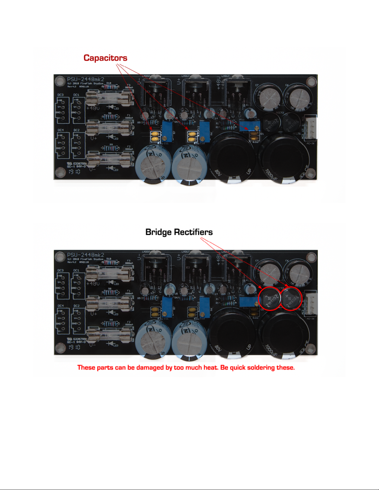
Step 2. Solder all ceramic capacitors to the PCB. These are the small yellow components.
Step 3. Solder the bridge rectifiers, RECT1 and RECT2. These are the small circular components that have a “chopped-o"” side.
Note the proper orientation. Follow the guide printed on the PCB.
Page 8

PSU-2448mk2 Power Supply Kit
Step 4. Solder the (3) LEDs shown below. The LEDs are located under the fuses.
The LEDs require the proper polarity for it to work. It has a (+) Terminal and a (-) Terminal. See the photo below on how to
mount the LED correctly. Note the “Short Leg” and “Long Leg” of the LED and insert it in the orientation shown below.
Page 9

PSU-2448mk2 Power Supply Kit
MOUNT the LEDs as close as possible to the PCB board so its height would not interfere with the fuses.
Note: You may wire one of the LEDs to a front panel LED indicator lamp instead. Use the Panel-Mount LED that came with your
1u Power-Transformer Kit.
Page 10

PSU-2448mk2 Power Supply Kit
Step 5. Solder all small electrolytic capacitors. These capacitors also have polarity markings. One side will be marked as (-). This
is the Negative terminal. Install the capacitors with the negative terminal inserted at the bottom hole.
To lessen chances of errors, all capacitors are oriented in the same direction. (Negative terminal down).
Step 6. Solder the trimmer resistors. Note orientation of trimmer resistors.
Page 11
PSU-2448mk2 Power Supply Kit
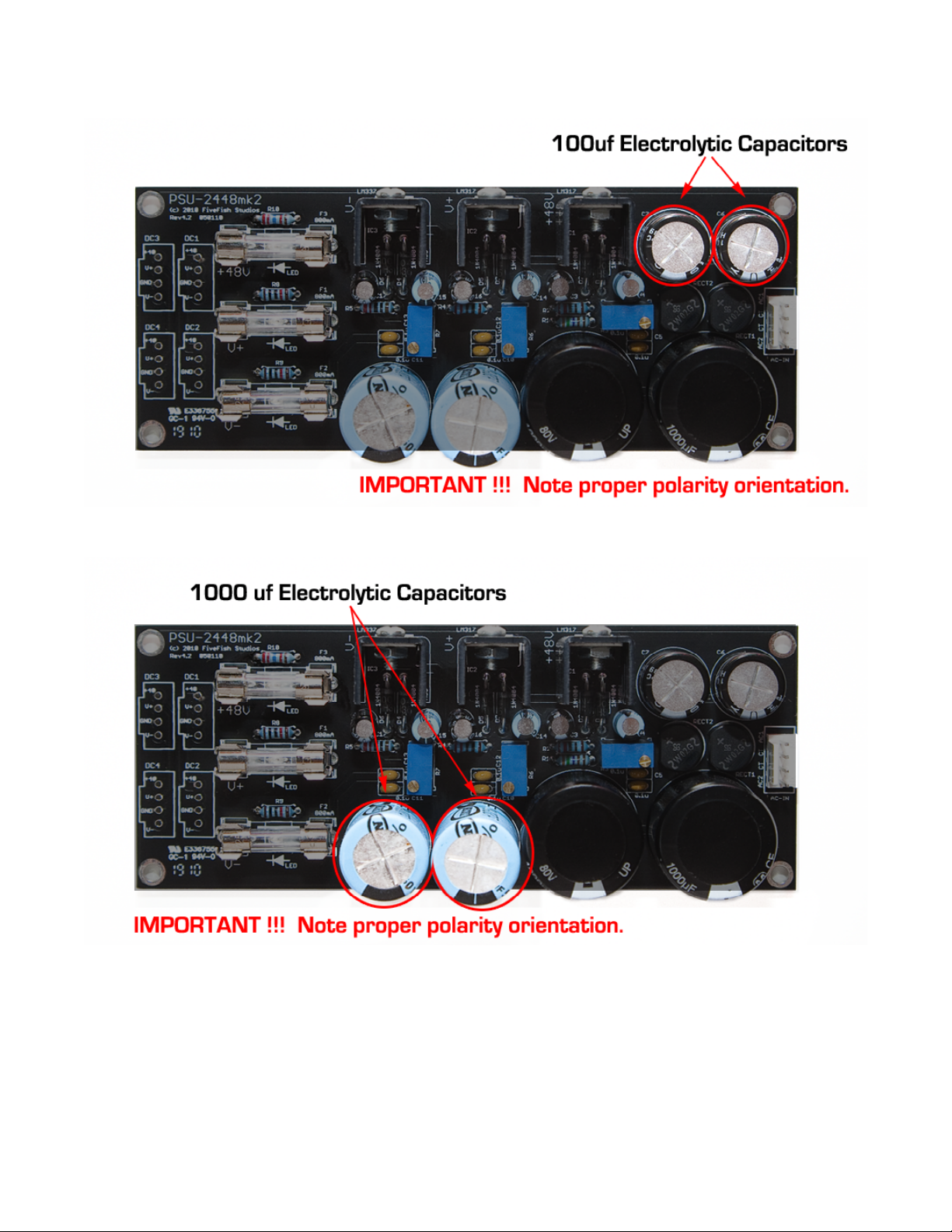
Step 7. Solder the medium sized, 100uf electrolytic capacitors.
Step 8. Solder the tall 1000uf 50V electrolytic capacitors.
Page 12
PSU-2448mk2 Power Supply Kit
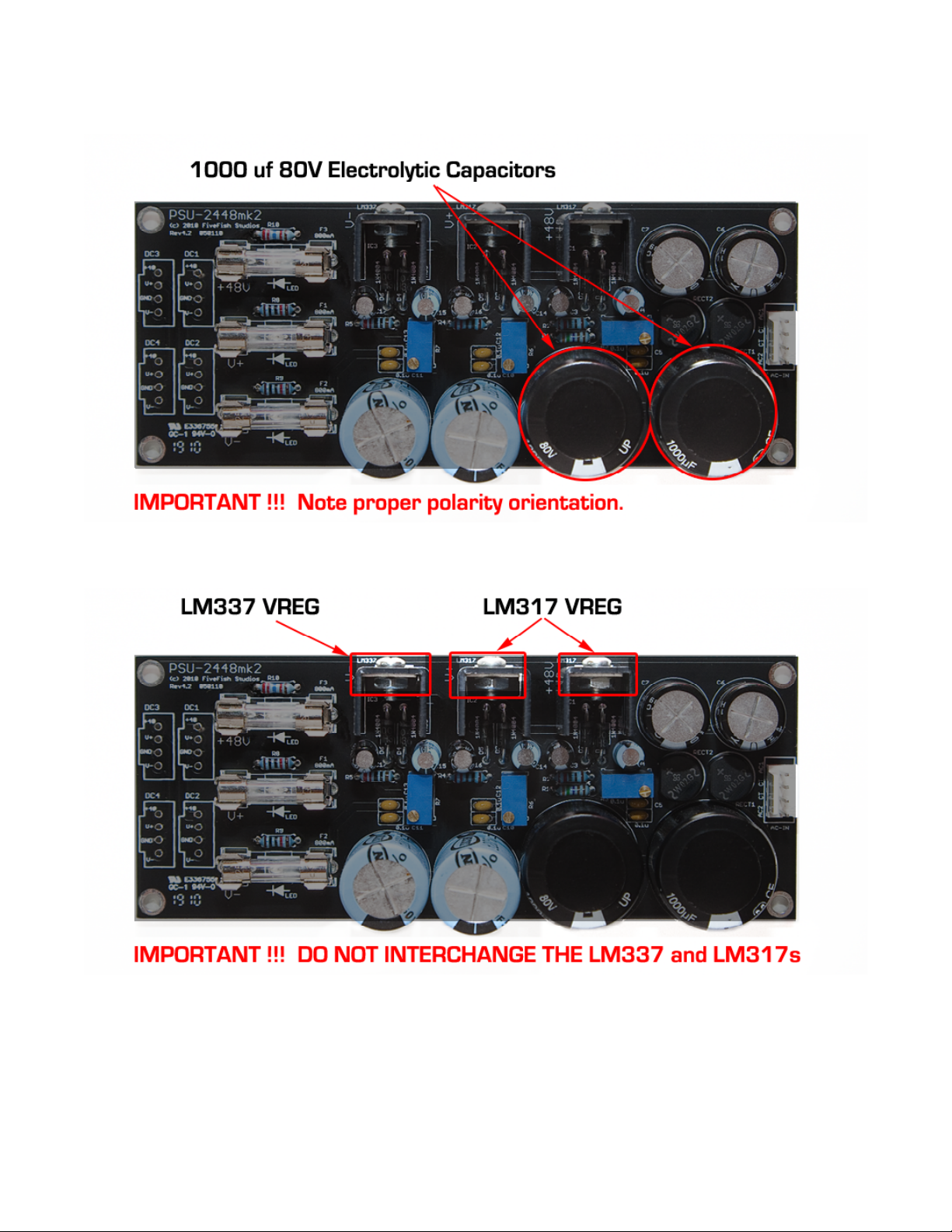
Step 9. Solder the 1000uf 80V capacitors. These are snap-in type capacitors. You need to do a slight twisting motion when
inserting the capacitor leads into the holes.
Step 10. Solder the three voltage regulators. For aesthetic reasons, keep all their height at the same level. The flat side (i.e. metal
side) of the regulators should be facing out towards the top edge of the PCB.
VERY IMPORTANT!!! Please note that the three voltage regulators look the same but are DIFFERENT.
The positive voltage regulator is an LM317,
and the negative voltage regulator is an LM337.
DO NOT INTERCHANGE the two regulators or you will damage them. Read the marking on the body!
Page 13
PSU-2448mk2 Power Supply Kit
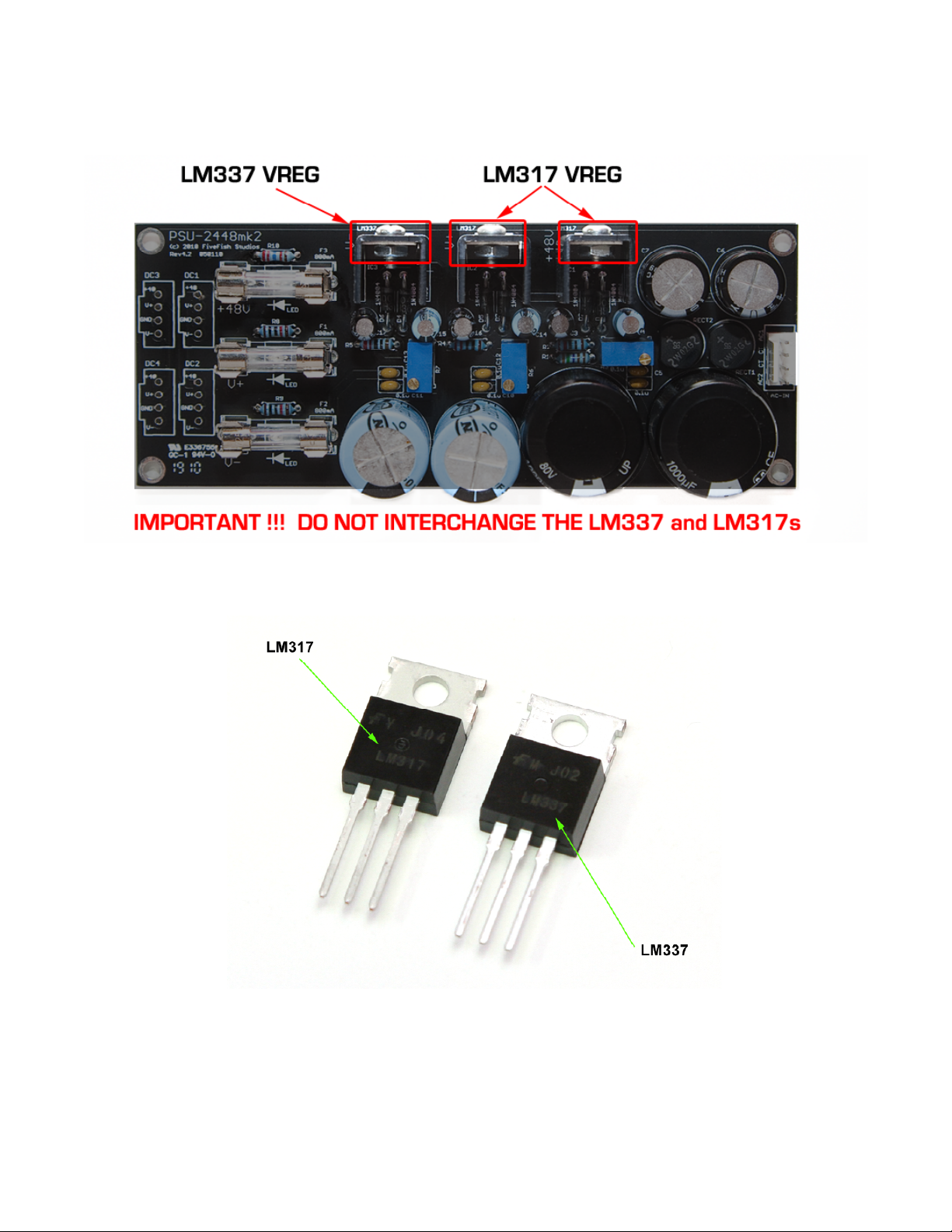
Using the photo below as a guide, from LEFT to RIGHT, the regulators are LM337, LM317, LM317.
Page 14

PSU-2448mk2 Power Supply Kit
Step 11. Install TO-220 heatsinks to your regulators. Use small nut and bolts to fasten the heatsinks to the regulators.
Note: You don’t need to install insulators. Just make sure the 3 heatsinks do not touch each other, or the metal part of your
case. Otherwise, you’ll be creating a short and destroy your regulators.
IMPORTANT !!! If you want all voltage regulators mounted on one single, big heatsink, then you MUST use TO-220
insulators to mount them.
Page 15

PSU-2448mk2 Power Supply Kit
Step 12. Install the (6) fuse clips.
IMPORTANT!!! Note the proper orientation of the fuse clips. One end of the fuse clip has a “stopper”, and the other end is open.
The “closed end” of the fuse clips should be mounted as shown below.The “open ends” of the fuse clips should be facing each
other. (so you can later mount the fuse cartridge later.)
Step 12. Insert the (3) Fuses into the fuse holder clips.
And we’re done. Next step is connecting the PSU PCB to our power transformer, and adjusting the output voltages.
Page 16

PSU-2448mk2 Power Supply Kit
PSU-2448mk2 Wiring Guide
Connect AC1, AC2 and CT pads of the PCB to the secondary windings of your power transformer.
If you’re using the FiveFish Studios 1u PWR-TRAFO kit, wire the transformer as follows:
On the secondary side, connect the RED and ORANGE together. (this will be the center-tap wire CT). The center-tap wire will
connect to the CT pad on the PCB. (The CT pads are the 2 middle pads on the PCB AC input)
Connect the BLACK wire to AC1 on PSU PCB.
Connect the YELLOW wire to AC2 on PSU PCB.
OPTIONAL: The PSU kit uses standard 0.1” spaced pads for all input and output connections, so you can use MOLEX PCB
connectors as pictured above. (Molex connectors are not included in the kit. They can be purchased at Digikey.com or
Mouser.com. Any standard 0.1” header will work.)
Page 17

PSU-2448mk2 Power Supply Kit
PSU-2448mk2 Voltage Adjustment Guide
The voltages selected for this instruction assumes you’ll be using this PSU kit with the SC-1mk3 or X-12 preamp kit. If you’ll be
using this power supply with another project, adjust the output voltage accordingly to what you need.
1. Using a voltmeter, measure the voltage across the (+48) and GND terminals. We want a voltage reading of +48Volts. You
probably won’t exactly get 48Volts, so using a small screwdriver, adjust leftmost trimmer R3 to measure 48 volts at the
outputs.#Turn the screwhead COUNTERCLOCKWISE to increase the voltage.
2. Next measure the voltage across (V+) and GND pads. Adjust the middle trimmer R6 to at least +20V at the outputs. Turn the
screwhead COUNTERCLOCKWISE to Increase the voltage
3. Next measure the voltage across (V-) and GND pads. Adjust the rightmost trimmer R7 to get –20V at the outputs. Turn the
screwhead COUNTERCLOCKWISE to Increase the voltage Note... since this is a (-) supply, increasing the voltage will direct you
towards (0) zero volts. You'd want to decrease the voltage (i.e. turn CLOCKWISE) to adjust the voltage to at least -20Volts.
4. DONE!#FINISH!#Power o", then connect the (V+), (V-), GND and +48V pads to your SC-1mk3 preamp or project.
NOTE:
1. After connecting your preamp/load to the PSU… you may want to re-check the output voltages just to be sure. Re-adjust if
necessary.
Page 18

PSU-2448mk2 Power Supply Kit
2. The SC-1mk3 and X-12 preamp have on-board, local voltage regulators. The local regulators adjust the voltage down to
+/-18V on the preamp board. So we want to feed the SC-1mk3 or X-12 board with at least +/-20V coming from the PSU.
PSU-2448mk2 Short-Circuit Protection
The PSU-2448 Power Supply kit uses LM317 and LM337 Voltage regulators. These voltage regulator chips have built-in short-
circuit protection.
However, in some cases, the built-in protection of the voltage regulator isn’t enough. Thus, when a short circuit happens (say
the V+, or +48V is accidentally shorted to GND), the voltage regulator may fail. A common symptom of a failed voltage
regulator is it won’t adjust no matter how you turn the trimmers, or it would only output a small voltage.
The fix is removing the faulty voltage regulator and installing a brand new one. The desoldering of the faulty regulator is a little
di$cult if you don’t have the proper desoldering tool.
To solve this problem, the new PSU-2448mk2 Power Supply Kit (Black face PCB) has (3) on-board fuses to protect the PSU (and
your equipment) from accidental voltage shorts.
Page 19

PSU-2448mk2 Power Supply Kit
PHOTO 1: In normal operation, you’ll see all (3) LEDs lit up. They are positioned under the fuses so you can see them clearly.
PHOTO 2: Let’s simulate a short circuit by bridging a wire between the +48V phantom power and Ground. You’ll notice the RED
LED lamp for the +48V fuse is now OFF. This means this particular fuse has OPENED to protect the PSU from the +48V short.
PHOTO 3: Replacing the fuse with a brand new one shows that we have +48V power back again – with no damage to the voltage
regulator.
NOTE: It is a good idea anyway to avoid shorting any of the power supply output voltage rails to ground. The above is just a
demonstration.
IMPORTANT: 110V/220V Mains power safety fuses should still be installed when wiring your power transformer. The above PSU
on-board fuses only protect the power supply regulators. They do not protect you from AC line, high voltage shorts.
Page 20
Table of contents


