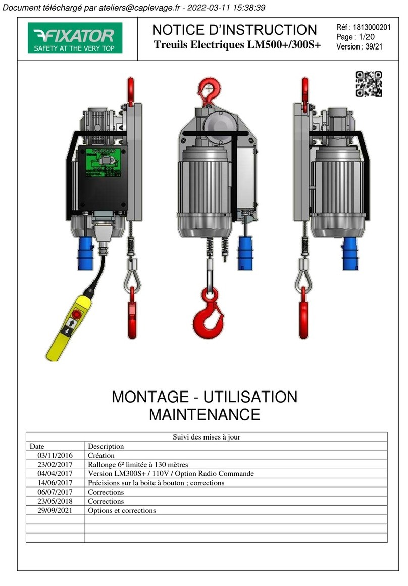
FIXATOR LM90A User manual

INSTRUCTION MANUAL
Electrical winches LM90A/LM250A
Réf : 1813000156
Page : 1/17
Version : 23/21
INSTALLATION –USE
MAINTENANCE
Monitoring of updates
Date
Description
08th Jun 2021
New format - type A for Radio option (modification 1300)

INSTRUCTION MANUAL
Electrical winches LM90A/LM250A
Réf : 1813000156
Page : 2/17
Version : 23/21
SUMMARY / PLAN
1 GENERALITIES ............................................................................................................................................................... 3
1.1 DESCRIPTION OF THE MACHINE .....................................................................................................................................3
1.2 GENERAL DESCRIPTION................................................................................................................................................3
1.3 COMPLIANCE WITH GUIDELINES AND STANDARDS;COMMISSIONING.....................................................................................3
1.4 SPECIFICATIONS .........................................................................................................................................................4
1.5 MACHINE LOGBOOK, ..................................................................................................................................................4
1.6 RECOMMENDATIONS FOR USE AND GENERAL SAFETY .........................................................................................................4
1.7 ANCHORING..............................................................................................................................................................5
2 INSTALLATION AND USE ...............................................................................................................................................6
2.1 INSTRUCTIONS FOR INSTALLATION,ASSEMBLY,COMMISSIONING AND USE -TRAINING..............................................................6
2.1.1 Suspended installation............................................................................................................................................6
2.1.2 Installation with deflection.....................................................................................................................................6
2.1.3 Reeving for lifting of load .......................................................................................................................................7
2.1.4 Power......................................................................................................................................................................8
2.1.4.1 Hoist connection.............................................................................................................................................................8
2.1.4.2 Commissioning................................................................................................................................................................8
2.1.5 Installation of cables for lifting...............................................................................................................................8
2.2 DIAGRAMS AND SAFETY EXPLANATIONS ..........................................................................................................................9
2.2.1 Main dimensions ....................................................................................................................................................9
2.2.2 Safety devices .......................................................................................................................................................10
2.3 DESCRIPTION OF THE WORK OR CONTROL STATION..........................................................................................................10
2.4 NORMAL USE ..........................................................................................................................................................10
2.5 DECOMMISSIONING..................................................................................................................................................10
2.6 WARNINGS ABOUT CONTRAINDICATIONS ......................................................................................................................10
2.7 RESIDUAL RISKS .......................................................................................................................................................11
2.8 TRANSPORTATION,HANDLING,STORAGE ......................................................................................................................11
3 MAINTENANCE - SETTINGS ......................................................................................................................................... 11
3.1 MAINTENANCE OPERATIONS ......................................................................................................................................11
3.1.1 Preventive maintenance .......................................................................................................................................11
3.1.2 Adjusting of the brake ..........................................................................................................................................12
3.1.3 Lubricating & controling a hoist cable..................................................................................................................12
3.2 TROUBLESHOOTING..................................................................................................................................................13
3.3 SPARE PARTS...........................................................................................................................................................13
3.4 DISPOSAL ...............................................................................................................................................................14
3.5 NOISE EMISSION ......................................................................................................................................................14
4 APENDICES.................................................................................................................................................................. 14
4.1 WIRING DIAGRAMS ...................................................................................................................................................14
4.2 OPTIONNAL RADIO REMOTE CONTROL ..........................................................................................................................16
4.2.1 Model ref 461025 .................................................................................................................................................16
The original of this document is in French. No translation can replace the original.
Thank you for purchasing a FIXATOR product. In the following pages we give you details of instructions
allowing you to safely use and maintain your equipment in good working condition. Please read these
instructions prior to commissioning the equipment: no installation operation, use and maintenance should
be performed until this document has been fully understood. These operations must also be carried out by
clearly designated personnel suitably trained.
The following symbol will alert you to hazards to watch out for: .

INSTRUCTION MANUAL
Electrical winches LM90A/LM250A
Réf : 1813000156
Page : 3/17
Version : 23/21
1Generalities
This notice covers the use of winches LM type
LM90A and LM250A (versions listed in §1.4).
1.1 Description of the machine
The LM is a portable electric reeving hoist for
unlimited hoisting cable movement (check
instructions on the hoist plate: "Type LM90A" or
“LM250A”).
The standard equipment includes:
- the unit with its carrying handle and the safety
hook; engine with main brake and protected by
thermal probe
- 2 travel end stopper
- 1 pendant control station (2,5 m) double insulation
IP 65 with 3 button: ascent, descent and emergency
stop (extension: 200 m maximum)
- male/female plug and cable power (0.50m)
- 1 manual
The LM winch cannot be used to lift or move
people or dangerous goods.
1.2 General description.
Diagram of typical installation:
This winch is designed for the lifting and traction of
loads. It is intended for professionals involved for
work, such as in an elevator shaft or on building
facades. The winch uses one steel cable (hoisting
cable).
The drive system consists of a pulley whose throat
has a special profile, and in which the cable is tight
under the effect of the load by two articulated
rollers. This allows an unlimited run of the hoisting
cable.
This technical design ensures a great security
provided you follow the instructions given in this
manual.
Each device carries labels information and
instructions. Constantly make sure that all these
labels are in place and legible.
The LM winch must be used exclusively with
special lifting cable, to fully ensure the safety and
efficiency.
Before its expedition by Fixator, each hoist is tested
to 110% of its capacity.
Additional kits exist:
ref : 438900
Extensions to the pendant control station (5G1) :
- 15m : ref 540134
- 30m : ref 540136
From serial number 1551 onwards, the pendant ref
462020 can no longer be used. Only use model
461020:
1.3 Compliance with guidelines and standards;
commissioning
This machine complies with the Machinery
Directive 2006/42/EC.
It is manufactured under a quality process according
to EN-ISO 9001: 2015.

INSTRUCTION MANUAL
Electrical winches LM90A/LM250A
Réf : 1813000156
Page : 4/17
Version : 23/21
A test prior to initial commissioning and after each
maintenance or dismantle must be performed with a
static test coefficient of 1.25xWLL and a dynamic
test coefficient of 1.1xWLL.
1.4 Specifications
The LM winch has a working load limit (WLL)
displayed on the winch plate.
Type
LM250A
LM90A
LM90B
CMU / WLL (kg)
250
90
Motor P (kW)
0.45
Voltage (V)
230V-50Hz
230V 60Hz
I Nominal / start (A)
3.5/11A
4.6/12A
Weight (kg)
21
Dimensions (mm)
219x260x503
T° for use (° C)
-10°C / +55°C *
Operating Speed (m/s)
0.1 (6m/mn)
0.28 (17m/mn)
0.33 (20m/mn)
Wire rope Ø and type
Ø5 galvanized steel
Minimum breaking load (kg)
1800
Upper limit switch
Yes
Lower limit switch
Yes
Service factor
S3 50% 30cy/h
* Use between -20° and -10°C is possible
providing a gradual and uniform preheating
unloaded operation is carried out, then the load can
be applied as soon as the hoist reaches a T ° - 10°C.
1.5 Machine logbook,
The contents of the logbook of this machine are not
provided; it is up to the owner to create or acquire
one in which the following is noted:
- the name of the person in charge of
equipment
- operator names and dates / periods of use
- serial numbers of components
- the number of hours of use,
- the characteristics of the cables used
- the number of hours the cables are used,
- a record of incidents and actions taken to
remedy them
- forecast dates of periodic inspections and
record of actual dates of inspections
1.6 Recommendations for use and general
safety
Before using this equipment, ensure:
- that you read and understand this entire
manual
- that no obstacles will obstruct the required
motion
- that the periodic inspection has been
performed and recorded,
- that the electrical installation is designed and
protected according to current regulations
- that your material is stable and aligned, freely
with the load
- the load or machine movements will not trap
or crush you or other people; signal and block
access to the area under the load
- you can communicate with help in case of
need,
- that you have adequate lighting
ensure :
- every day the correct operation of the
mechanisms, brakes, and emergency stop
- periodically the electrical cables, limit
switches, structural elements and wire ropes
- regularly the presence of travel end stopper,
the presence of plates and safety instructions
(and their readability),
- safety of the suspension structure
- there is no accumulation of snow, ice, debris
or materials on the winch,
- that there are no obstructions on the façade or
in the shaft
- at the end of work, that the deactivation is
complete.
- If a charge is to be raised by multiple devices,
the installation of these must be preceded by a
technical review by a competent technician
and then conducted according to this study,
including to ensure the constant distribution
of the load in suitable conditions.

INSTRUCTION MANUAL
Electrical winches LM90A/LM250A
Réf : 1813000156
Page : 5/17
Version : 23/21
During the operations of lifting, up and down,
the user must constantly observe the load and the
free end of the cable to prevent any risk of collision.
The load must be constantly guided (EN14492-2);
otherwise the use of rotation-resistant wire rope is
necessary.
Check and apply local regulations concerning
the installation, use, maintenance and control of
lifting devices.
See also contraindications §2.6
1.7 Anchoring
Verify that the anchoring point is strong enough for
the effort to apply.
If the anchoring is not provided by FIXATOR each
anchor must withstand, without any deformation, up
to 2.5 times the WLL of the winch, that is
2.5x90=225 kg (respectively 2.5x250=625 kg for a
WLL of 250kg), and remain stable when subjected
to this load.
(special case of reeving 2:1, the resistance must be
of 5 times the WLL, that is 450 kg (respectively
1250kg); see §2.1.3)
Minimal withstanding of the hoist and/or pulley
anchorage :
If the fixing of the unit must be in a dangerous place
for the operator, the safety precautions provided for
by the work’s regulation must be taken to exclude
any risk uncontrolled in this operation. It is perhaps
better in this case to implement the hoisting cable
into the device before the anchoring operation.

INSTRUCTION MANUAL
Electrical winches LM90A/LM250A
Réf : 1813000156
Page : 6/17
Version : 23/21
2Installation and Use
2.1 Instructions for installation, assembly,
commissioning and use - training
Les opérations d’installation et d’utilisation doivent
Installation and use operations must be performed
by personnel specially trained by the manufacturer
or its dealers, duly authorised by their employer.
Depending on your country, regulatory inspections
may be necessary.
Make sure you have:
-a sufficient length of special cable Ø5 mm
- an adequate length of supply cable and
suitable number of wires with suitable cable
section,
- Accessories you may wish to use
The reaction in the anchorage of hoist and/or
pulley are different according your installation;
check your case with a qualified technician :
2.1.1 Suspended installation
It's the simplest mounting and the most common.
Device in suspension and direct traction or lifting.
The anchoring of the device must be done
exclusively by its hook and never by its handle.
There is no way to anchor the hook of the cable to
the fixed point to get the device moving on the
cable.
The hook of the machine must be placed in the
body of the attachment point, so that this body is at
bottom of hook. The pawl
of safety of the hook must
close completely.
If a gene appears in the
articulation of the apparatus
with the body of fixing
hook, it is necessary to
interpose a sling of
appropriate capacity.
Check each element
of connection capabilities
to ensure your safety.
2.1.2 Installation with deflection
- Device suspended ; indirect traction or lifting.
This case requires a deflection pulley anchored to a
fixed point.
- Device on ground and lifting through a deflection
pulley.
( this is not a reeving; refer to §2.1.4)

INSTRUCTION MANUAL
Electrical winches LM90A/LM250A
Réf : 1813000156
Page : 7/17
Version : 23/21
The resistance of the pulley and its
anchorage must be calculated for a double effort of
the lifted load.
2.1.3 Reeving for lifting of load
Use the reeving kit ref 438900.
This assembly allows you to double the capacity of
the device. In return, the speed is decreased by half.
The LM must not be otherwise than with this
reeving kit assembled. Additional system must not
be added.
The reeving kit consists of an anchor carrier strand
and a reeving block with a hook and a spring.
The user should note that when reeving, the
required length of wire rope is at least twice the lift
height, plus at least 1 meter of apparent slack
strand.
The limit spring mounted on the lower pulley is
intended to replace the high limit stop.
A stop may still be placed on the loose strand to
serve as low end stopper.
In case of reeving, double the maximum load
to be taken into account for the calculations of
security.
NOTA : take care to mount the pulley block so that
its limit spring is located on the cable between the
pulley and the entry in the hoist (see figure).
Check the triggering of your travel limit
switch before use; a repositioning of the stoppers
may be necessary depending on the configuration of
job.
Check the capacity of the anchoring points.
When operating with the reeving system, especially
the operator will ensure that the load is not turning
on itself, to avoid tangling the three strands of the
cable (two strands loaded and the slack side).

INSTRUCTION MANUAL
Electrical winches LM90A/LM250A
Réf : 1813000156
Page : 8/17
Version : 23/21
Stop immediately if the loose strand comes to
tangle with the other strands.
2.1.4 Power
The installer must ensure that the power supply is
compatible with the specification of the winch.
The power supply must be protected
upstream by a 30 mA differential switch. The
installation must be in accordance with EN 60204-
1. Power outlets must be calibrated to 10A.
The power cable to the LM control box must be
flexible cable (Class 5). Beyond 30m, it must be
held in place by a suitable anchorage clamp.
EXTENSION SECTION (mm²) at 230V
Type :
0-50m
50-100m
100-180m
3 wires
P+N+T
1.5²
15AWG
2.5²
13AWG
4.0²
11AWG
If the LM winch is powered by a generator, check
that it delivers at least the voltage and power
required at the start of the winch (min 3kVA).
2.1.4.1 Hoist connection
- Connect the button box to the socket on the
winch.
- Connect the main power plug.
2.1.4.2 Commissioning
- Unlock the emergency stop if
necessary
- Press the UP button to lift or pull the
load
- Press the DOWN button to lower the
load
At any time, in case of imminent danger or
need, press the Punch red button to stop any
movement of your hoist.
2.1.5 Installation of cables for lifting
Use protective gloves when handling wire
rope.
Check the condition of the cable and its length
(working height + 2m).
Check the condition of the hook and safety latch.
Avoid the formation of loops when unwinding..
The end of the cable should be clean and sharp.
pour votre sécurité, n’utiliser que des câbles
FIXATOR
Put the end stopper on the wire rope (the spring
being directed to the winch). Block with an Allen
key.
Insert the end of the wire rope through the bottom
opening A. press the UP button on the pendant
control while pushing the wire rope so that it
engages in the throat of the pulley.
When the rope come out through hole B, continue
the movement so as to obtain a sufficient length of
wire rope.
PS : a second stopper is provided to stop the
descent; position the spring on the side of the
winch:
A
B

INSTRUCTION MANUAL
Electrical winches LM90A/LM250A
Réf : 1813000156
Page : 9/17
Version : 23/21
Check the operation of the limit switches of the
winch.
For your safety, use only FIXATOR cables.
Ensure that the cable above the hoist (taut) does not
touch surfaces or angles.
Ensure that the outgoing winch cable (slack) is free.
Do not let the loaded rope become slack if the load
is not stable, resting on a strong enough support.
2.2 Diagrams and safety explanations
Installation and use operations must be
performed by personnel specially trained by the
manufacturer or its dealers, duly authorised by their
employer.
The maximum capacity of the hoist (WLL) should
be the basis for calculations of anchor strength.
2.2.1 Main dimensions
(depends according versions)

INSTRUCTION MANUAL
Electrical winches LM90A/LM250A
Réf : 1813000156
Page : 10/17
Version : 23/21
2.2.2 Safety devices
- A main brake acts on the engine in case of
power supply failure
- An upper limit switch sensor stops lifting
when the spring touches the plate.
- A lower limit switch sensor stops lowering
when the spring touches the plate.
- An electrical emergency stop placed on
pendant control acts immediately and stops
the winch to the ascent and the descent.
- Mechanical locking prohibiting the
simultaneous action of the up and down
commands.
- Electrical protection of the pendant control :
class 2.
- Fuse protecting the command, in the electrical
box.
- Hooks with safety latch.
The single-phase motor is protected against
excessive warm-ups by a probe inserted into the
coil. This probe prohibits operation by interrupting
the control circuit as long as the temperature of the
coil is not back to an acceptable value. In case of
intensive work or high duty, we suggest to allow a
15 minutes break every 10 minutes of work to avoid
overheating.
2.3 Description of the work or control station
"Up" and "down" hoist movements are controlled
from the pendant control.
Never stand under the load.
In case of a command error, wait for a complete
stop of motion before performing another
command. The control buttons are held type
buttons.
Limit stops are not operating devices but safety
devices. They should therefore not be used
voluntarily but only serve as shutoff devices in case
of involuntary exceedance of the expected travel.
Never stay or work under load. If necessary, have a
barrier of security on the floor around the area at the
vertical of the load.
Avoid heavy slipping: Wait for a complete
stop of your installation before resuming
movement.
Check regularly that no obstacle is located along the
path of movement (above and below the load).
2.4 Normal use
This hoist is designed for lifting loads.
It is designed for professionals involved, for
example, in work in elevator shafts or on
façades.
Press on «» to lift and on «» to lower.
Release the buttons to stop the movement. If
it is not stopped, press the Emergency Stop.
If it is not working, remove the main plug
and have your hoist maintained.
2.5 Decommissioning
After work, or during an prolonged shutdown, or if
preventive maintenance tests (see §3) are not
satisfactory, put your load on the floor or a secure
access level. Disconnect the hook from the load
when it is resting stable on a fixed and solid
support.
The device can remain attached provided that it is
protected from the weather and in a dry place.
Snap your emergency stop.
Unplug and store your pendant control box.
Store your power supply cable.
2.6 Warnings about contraindications
It is forbidden to use this product:
- if you are not a trained professional
- to exert a force or lift a load greater than the
WLL (90 or 250kg) if it is not described in
this manual,
- to lift people,
- in harsh conditions (extreme or corrosive
environment, high magnetic fields, etc.)
- in potentially explosive atmospheres
- to perform work on energized power lines,
- to carry loads themselves dangerous (molten
metals, acids, bases, radioactive material,
fragile loads etc)
- in combination with other lifting equipment if
it is not listed in this instruction manual,
- with loads with a wind surface area >2 m² if it
is not listed in this manual,
- with a wireless remote control system not
mentioned in this manual
- in the event of specific risks (wind> 14 m / s,
T ° <-10 ° C or> 55 ° C, storms etc)
- with worn or deformed cables

INSTRUCTION MANUAL
Electrical winches LM90A/LM250A
Réf : 1813000156
Page : 11/17
Version : 23/21
- with lubricated cables with products
containing bisulphite or MoS2 (Molykote ®,
etc)
- To apply a load on the loose strand of the
hoist.
- To use the wire rope as a means to sling the
load
2.7 Residual risks
The use of cable damaged or not suited to the
device is the major risk of accident and failure.
Check that your equipment has not been
subject to vandalism, theft, or damage.
Never disable the safety features.
Never swing a load voluntarily.
Do not block a control.
In case of continuous operation for more
than 15 ', the surface temperature of the motor can
begin to rise significantly.
2.8 Transportation, handling, storage
To transport your machine from one site to another,
remove the cables from your hoist.
Store the various components of your equipment in
a clean and dry place.
3Maintenance - Settings
Maintenance operations must be performed
by personnel specially trained by the manufacturer
or its dealers.
3.1 Maintenance operations
LM hoists must be reviewed at least once a year and
every 100h. In harsh environments (sandblasting,
marine, back and forth operation at full load, doubts
about the proper use etc) a higher frequency of
verifications may be required.
Load lifting winches are intended for a limited
lifetime; beyond that, a return to factory is
imperative.
For the hoist LM
type LM90A, the ranking is A2.
type LM250A, the ranking is A1.
In some countries, periodic audits and reviews of
commissioning are mandatory.
3.1.1 Preventive maintenance
These operations must be performed by a
competent person trained by FIXATOR or its
dealers. The FIX022 manual details these annual or
control operations.
Check:
Daily :
The quality of your anchors and of the 2 hooks
(latch).
The good clamping of the travel end stoppers on
your cable.
The good general condition.
Monthly :
The proper functioning of the safety devices
(emergency stop, limit switches, brake).
The good condition of the wire rope (§3.1.3)
The overall proper functioning by performing a full
movement at the rated load.
Every year and every 100h :
Check the groove pulley.
Check the bearings, rudder, gear...
Check the motor brake.
Control each security (cf §2.2.2) at the rated load.
Clean and grease the gears (e.g. BIMO EP or
Klubersynth AG14-61)

INSTRUCTION MANUAL
Electrical winches LM90A/LM250A
Réf : 1813000156
Page : 12/17
Version : 23/21
3.1.2 Adjusting of the brake
Remove the cap (5) that is on the ventilator lid (1).
→Increasing the braking: turn the brake screw (6)
progressively counter clockwise and check that the
brake does not slide during the lowering.
→Decreasing the braking : turn clockwise.
TO RELEASE THE BRAKE SYSTEM:
If necessary, it is possible to unlock the brake
manually, by pressing the (8) pivot. After each
operation, a load test must be performed.
FIXATOR or its dealers can train your staff for the
maintenance of your winches.
For your safety and to benefit from the full
guarantee of the manufacturer, use only original
FIXATOR parts (ask the complete list of spare
parts).
3.1.3 Lubricating & controling a hoist cable
The hoisting cable must be regularly greased or
lubricated with Teflon.
For this, use for example:
- IGOL SHP 50 grease
- A lubricant spray PRO-LUBE Teflon.
Never use products containing bisulphite or MoS2
(Molikote).
Only cables recommended by FIXATOR provide
safe hoist operation. The removal’s criteria to
follow are those of the ISO4309.
The diameter should not be reduced by more than
10% (for wire rope Ø 5 mm) : min 4.5mm
The cables must be replaced in the following cases:
- More than 10 wires broken over a length of
20 cm for wire rope Ø 5 mm.
-“Basket”deformation or rupture of one of the
cable strands.
- Cable crushed, unravelling.
- Considerable oxidation
When using a plastic return pulley, they must be
replaced once they have been used with cables
having at least one broken wire.

INSTRUCTION MANUAL
Electrical winches LM90A/LM250A
Réf : 1813000156
Page : 13/17
Version : 23/21
3.2 Troubleshooting
Faults
observed
Potential causes of the fault
Remedies
The motor
does not rotate
The temperature sensor is activated
The motor has a mechanical fault
The contactor in the hoist is out of order or
disconnected
The limit switch is activated
Fault in the control circuit
Fault in the power circuit
Power supply fault
Current escape to earth
Batteries of the remote control out-of-order
Wait for a drop in temperature
Check the motor
Reconnect or replace it
To be checked by a competent person
Check
The hoist does
not lift
The grooved pulley is worn or dirty
The condenser is disconnected or out of
order
The temperature sensor is activated
The motor is blocked
The contactor on the hoist is out of order or
disconnected
The limit switch is activated
Fault in the control circuit
Fault in the power circuit
Verification
Verification
Wait for a drop in temperature
Verification (maintenance)
Reconnect or replace it
To be checked by a competent person
The hoist does
not lower
The temperature sensor is activated
The motor is blocked
The contactors in the hoist are off or
disconnected
Error in the control circuit
Error in the power circuit
Wait until it cools
Check the motor
Reconnect or change
To be checked by a competent person
The motor is
powered but
stops (snoring
sound)
The capacitor is disconnected or out of
service (for single phase hoist only)
The motor is blocked
Power cable section too thin
Verification
Verification (maintenance)
Replace the power cable
The hoist does
not lift the
load
The groove pulley is worn or dirty
The capacitor is disconnected or out of
service (for single phase hoist only)
The temperature sensor is activated
Power cable section too thin
The wire rope is inserted in wrong way
Verification
Verification
Wait until it cools
Replace the power cable
Verification
Current too
high
The brake is out of service
The capacitor is disconnected or out of
service (mono phase hoist only)
The motor is blocked
Verification
Reconnect the capacitor or change it
Verification (maintenance)
Slow slide
The groove pulley is worn or dirty
The brake is worn
The adhesion system is worn or dirty
Verification
Adjust the brake
Verification
3.3 Spare parts
Use only FIXATOR original spare parts.
Note and send the information listed on the plate
shown below before requesting parts.

INSTRUCTION MANUAL
Electrical winches LM90A/LM250A
Réf : 1813000156
Page : 14/17
Version : 23/21
Main wear parts and estimated replacement
frequency (highly dependent on actual usage) :
Grooved pulley ref 540616 100h
Pinion shaft ref 540604 /
Pressure system ref 540608 500h
Travel end stopper ref 540620 /
Capacitor 40uF ref 540582 /
Pendant control ref 461020 /
Motor cap ref 540601 /
Fuse ref 244612 /
3.4 Disposal
Disassembly and disposal of the hoist must be in
accordance with the current regulations in force.
Electrical components, gear oils, greases, etc ...
should be separated and sent to the appropriate
treatment locations.
3.5 Noise emission
The A weighted sound pressure levels at
workstations is less than or equal to 70 dB (A)
4Apendices
4.1 wiring diagrams

INSTRUCTION MANUAL
Electrical winches LM90A/LM250A
Réf : 1813000156
Page : 15/17
Version : 23/21

INSTRUCTION MANUAL
Electrical winches LM90A/LM250A
Réf : 1813000156
Page : 16/17
Version : 23/21
4.2 Optionnal radio remote control
A remote control is regarded as a control
device; its proper implementation must respect the
resulting rules. For maximum handling safety of the
radio remote control, it is recommended to respect
the instructions provided in the detailed manual (in
French, English and German).
If using multiple radio controls on the same site,
assign different radio channels (see § of the detailed
instructions). Clearly mark your pairs of
“Transmitter/Receipter”.
In some cases, it is essential to modify and
customize the settings of the transmitter and
receiver to ensure the uniqueness of the installation.
To obtain all details for the use of the remote
control, refer to the instructions (see chapter of the
detailed instructions).
The user must have undergone suitable training, and
must be capable of driving by radio remote control.
The user must always have the visibility of the
operation that he is carrying out.
Remember to change the batteries (1.5V AAA) or
to recharge the batteries if the charge level is low.
Service the equipment, and carry out periodic
inspections depending on the intensity of use.
4.2.1 Model ref 461025
This model follows the recommendations of
EN60204-32:2008
It contains a transmitter
(IP65) and a receiver
with internal antenna
(IP66 –range 75 to
100m).
Frequency band : 2405-
2480MHz
The receiver must be
positioned throughout the scratches on the electric
box cover of the LM.
Plug then the connector instead the pendant control.
START :
- Make sure the red STOP button is pressed
- Unlock by turning the STOP button. The upper
LED lights up (GREEN if the batteries are OK,
RED otherwise); The lower LEDs flash.
- Press the 2 START buttons simultaneously for 1
sec.
- Release; The lower LED goes out.
STOP :
- Automatic after 3 min without action;
- Press the STOP button
Your kit is preset for associated operation.
To add a Receiver / Transmitter association:
- Start the transmitter you want to associate
- Press the F button in the Receiver
- Press the S button in the Receiver
- Press the Up and Down buttons on the transmitter;
Hold while the LEDs have the following sequence:
Continuous red then 2 flashes green
- Release the Up button; The LEDs flash 1 time in
Green
Simultaneous use of 2 transmitters is not allowed.
You must disconnect the transmitter to use the
other:
- Start the transmitter you wish to disconnect
- Press the Start key on the left
- Press the stop button.
To erase all associations in the receiver:
- Press the F button in the Receiver
- Press the S button in the Receiver for 4 sec.

INSTRUCTION MANUAL
Electrical winches LM90A/LM250A
Réf : 1813000156
Page : 17/17
Version : 23/21
The original of this document is in French, no translation can replace it.
P.A. 8, rue du Bois Rinier - B.P. 10041 –49181 ST BARTHELEMY D’ANJOU (France)
TEL : + 33 (0) 2 41 31 17 00 –FAX : + 33 (0) 2 41 31 17 10
http://www.FIXATOR.fr –e-mail : info@FIXATOR.com
F
S
This manual suits for next models
2
Table of contents
Other FIXATOR Winch manuals
Popular Winch manuals by other brands
Gigglepin
Gigglepin GP25 owner's manual

Ramsey Winch
Ramsey Winch RPH 133,4 Operating, Service and Maintenance Manual

KC
KC 30.000 manual
Columbus McKinnon
Columbus McKinnon YaleMtrac Operating and maintenance instructions
Scheppach
Scheppach hrs 250 Translation from the original instruction manual
Comeup
Comeup Cub3 instruction manual
