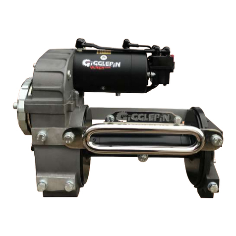
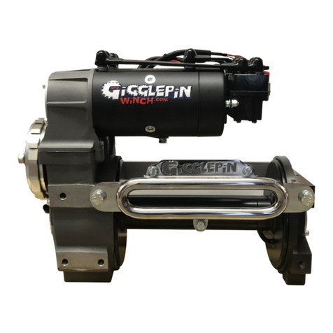
Gigglepin GP25 User manual

GP25 Owners Manual
Serial numbers GP251001 onwards
www.GigglepinWinch.com
+44 (0)1732 463600


This is your GP25!
This GP25 has been hand crafted to your personal specification.
It is ready for a life of pulling hard.
But every winch is different, so tell us about you winch story and
what you do with your GP25
What is your Winch Adventure?
Let us know through our email or social media!
If you need any advice or spare parts don’t hesitate to get in touch
Serial Number
TopHousing Ratio
Drum Length
Short Standard
Motors
Solenoid
Hurricane Fitted
Yes No
MBS Fitted
Yes No
Notes
Built By
Build
Date
GigglepinWinches #GigglepinWinches


1. Introduction Page 1-3
a. What’s in the Box 1
b. How do I Fit my GP25 2
2. Application information Page 2-6
a. Rope 3
b. Using Your GP25 4
c. Electrical 5-6
d. Brakes (including MBS) 6
3. Rigging and Winching Advice and Tips Page 7-8
a. Common Winch Hand Signals 8
b. Winch Remotes and Radios 8
4. Winch Maintenance Page 9-10
a. Maintaining Your Winch 9
b. Maintaining Your Rope 10
c. Top Tips for Your GP25 10
5. Warranty Page 11
6. Contact Information Page 11
7. Technical Data Page 13-21
a. TopHousing Diagram 13-14
b. LowerHousing Diagram 15-16
c. Winch Wiring Diagram 12V 17
d. Winch Wiring Diagram 24V 17
e. Winch Wiring Diagram 12V Fitted With MBS 18
f. Winch Wiring Diagram 24V Fitted With MBS 18
g. Winch Dimensions –Short Drum 19
h. Winch Dimensions –Standard Drum 20
i. GP25 FairLead Mounting Underwound 21
j. GP25 FairLead Mounting Overwound 21
8. Glossary Page 22
9. Ratio Information Page 23
Table of Contents

The Gigglepin GP25 competition winch has been designed and built to give you the highest
levels of performance and reliability in a demanding world. Using the best materials and
designs that set it apart from all of its competitors, it is the standard to which others aspire.
Our winches have been built to give our end user total reliability in the toughest situations,
and supply unequalled power and speed at those critical moments.
This manual will provide you with the information that you require to install, use and
maintain your Gigglepin winch. These are shown below are shown throughout the manual.
Warning –Procedures which must be followed precisely in order to avoid risk of personal
injury.
Caution - This calls attention to procedures which must be followed to avoid damage to
winch components.
Note –This calls attention to methods which make a job easier or gives helpful hints.
The GP25 should be respected and used correctly.
Winches are not designed to lift, support or transport personnel.
1
Congratulations on the purchase of this GP25 Winch!
When you open the box you will find the following inside -
- GP25 built to your specification
- Instruction Manual
- Sticker Pack
- T-Shirt
1. Introduction
a. What’s in the box

The GP25 has 18 symmetrical M12 mounting bolts giving it superior winch security in the
toughest of situations. When fitting your GP25 winch a minimum of six retaining bolts on one
face must be used at all times.
Note - The four missing mounting bolts and washers from the front of your winch are used
to secure the winch to the shipping pallet.
If possible Gigglepin recommend using two of the three mounting faces to hold the winch
securely, and using twelve mounting bolts where possible. Gigglepin recommend the use of
winch mounts made from a minimum of 8mm steel plate. Rear mounting bolts should not go
into the casing more then 20mm.
Gigglepin DO NOT recommend the use of tubular style winch mounts or wide mouth fairleads.
Your GP25 arrives fitted with two aluminium BraceBars to the rear of the winch. We recommend
that the BraceBars are retained where possible, unless the rear mounting points are to be used.
The GP25 is best mounted standing upright. However it can be mounted at various different
angles, but we recommend this must not be less than 20 degrees from horizontal, so as not to
affect gearbox operation and to prevent oil pooling in the TopHousing.
The Winch can also be mounted in a reverse position, but care must be taken to install the
Fairlead and rope in the correct position.
Caution - We do NOT recommend the winch is mounted laid flat.
Warning - Please remember that winch mounts need to be strong and securely fastened to
the vehicle or platform. Weak or bent mounts could result in equipment failure and
possible personal injury.
Fitting your Fairlead
You must fit the Fairlead to the correct location dependant on how your winch is installed.
With the winch in the upright (Section 7, Page 25) position, the FairLead needs to be fitted to
the lower front mounting points. If using the winch in a reverse position, the FairLead would
need to be mounted at the top (Section 7, Page 25).
It is also very important that the 3x M8 support bolts are used (Not used on short drums).
These can be fitted in two ways -
- Drill and tap your winch mounting plate, then trim the bolt to the correct length so it does
not interfere with winch rope. Note - This is our recommended method.
- Drill a hole through your winch mount and use the nuts and bolts supplied.
After fitting your FairLead, make sure there are no sharp edges on the mount that might
damage your winch rope.
2
A GP25 winch is designed to move a load at ground level or up or down an incline. It is not
designed for, nor intended for hoisting.
A GP25 winch is not designed to be used to lift or move people.
A GP25 winch is for intermittent use and is not designed for continuous use.
If the winch motors become hot, allow the winch motors to cool before continuing to winch.
If the winch stalls during operation, stop pulling! DO NOT continue to apply power to the
winch. This can damage your winch and your electrical system.
Re-evaluate the rigging, check for obstruction and double-line if required.
2. Application Information
b. How do I fit my GP25

3
GP25 Winches are designed to be operated using synthetic winch ropes (we do not
recommend the use of steel cables with this winch).
The GP25 winch is designed to be used in the upright position and the rope should be
installed from under the drum. This is called “Under wound”.
If the winch is mounted back to front (in a reverse position) the rope will be installed over the
top of the drum to allow the drum to rotate in the correct direction so the brake still works.
This is called “Over wound”.
Note - From the top = over wound. From the bottom = under wound.
Caution - the use of steel rope is not recommended.
Fitting a Rope to a GP25
The GP25 winch drum is nylon coated for durability and has a welded loop on one side.
- If the winch is fitted in an upright position, pass the synthetic rope through the Fairlead and
under the drum.
- Bring the rope around the back of the drum and over the top. Then pass the end of the rope
through the retaining loop.
- Tie a simple stop knot and pull tight.
- Your rope is now secure and ready to spool the rope on to the winch drum.
- When retrieving the rope in a no load situation it is often advisable to pulse the winch so
the motors do not over rev.
-Be sure the rope is distributed evenly and tightly on the drum.
Warning - Over revving when retrieving rope in a no load scenario can cause premature
motor failure.
Caution - GP25 winches are very fast, be sure to be standing at least two metres from the
winch, always wear gloves and make sure there are no loops in the rope or debris that could
catch your hands.
Rope Care and Use
Synthetic ropes are waterproof, float and are easier to handle than steel cable, however
debris can become caught in the strands, so gloves must be worn AT ALL TIMES.
Synthetic ropes do need to be cared for - follow these simple rules to increase rope longevity
and safety
- Never use on rocks without protection.
- Avoid constant High UV exposure.
- Keep ropes clean and dry.
- Check ropes for damage before and after use.
- If the rope is damaged, pinched, frayed or defective in any way, this will reduce the load-
carrying capability and should be replaced or repaired immediately.
- ALWAYS wear protective gloves when handling any winch rope.
a. Rope
Over wound Under wound

4
and
control solenoid and operating switch and
When mounting the switch, try to mount it in a position where it is easily seen and cannot be
approximately
load.
Gigglepin winches are very fast and powerful and require respect during use.
Here are a few tips and techniques that will help you get the most from your winch.
1. Place your winch switches in a location where they are easy to use and see, also
somewhere they cannot be knocked easily.
2. NEVER put your limbs close to the FairLead or near the winch during operation.
3. Always make sure you use a secure winching point/ground anchor.
4. Do not stall your winch, if your winch should slow down or near stalling, STOP. Check for
obstructions under or in front of your vehicle or possible faults with your electrical system.
5. Always allow the winch to stop turning before switching in a different direction.
6. When winching, try to keep your wheels turning at the same speed as the winch. This will
help aid traction and help get the most from the winch.
7. Always keep the winch line under tension this will help to eliminate the chance of over
spooling or ropes becoming wrapped around the winch, which to could lead to breakages
or premature rope failure.
8. Do not allow the cable to ‘Bunch’ on the drum this could lead to the tie bars being bent or
in the worst case actually breaking the winch casing and or damaging the rope.
9. Ensure power to winch is isolated before touching or handling any part of the winch.
c. Using your GP25

5
Your GP winch comes prewired and ready to use. It only requires heavy power, heavy earth
(ground) and switching wires to be connected.
Note - Please see below for exact requirements.
Note - Full wiring diagrams available in Section 7.
12 Volt Systems using 12v motors and solenoids
The GP25 winch requires a heavy 12v feed using a minimum of 50mm² cable. This needs to be
connected to the red M8 terminal on the rear contactor and preferably via a large 250amp
(continuous) cut off switch (see picture below).
The heavy earth connection needs to be a minimum of a 50mm² cable and connected to the
bottom of the motors using the M8 fixings supplied. This should return to the battery for best
results.
You then need to connect the red and green solenoid switch wiring. We recommend that you
fit a momentary on/off/momentary on style toggle switch inside the cab within easy reach of
the driver and ideally mounted next to your FreeSpool switch. A 12v switching feed is
required and should be fused.
We suggest using no less than a 65amp 12v alternator and recommend using Odyssey PC1500
or PC1700 batteries, although other gel and AGM type batteries designed for high discharge
are also suitable.
Caution - Electrical systems are only as good as their connections. Use high quality cables
and battery terminals. Gigglepin can supply a large range of components and premade
cables for any winch install. If you are unsure of your vehicles suitability please contact
Gigglepin.
Caution - Beware of smaller 100amp kill switches as they can burn out.
24 Volt Systems using 24v motor and 24v solenoids
The GP25 winch requires a heavy 24v volt feed using a minimum of a 50mm² cable. This
needs to be connected to the red M8 terminal on the rear contactor (solenoid) and preferably
via a large 250amp (continuous) cut off switch (see picture above).
The heavy earth connection needs to be a minimum 50mm² cable and connected to the
bottom of the motors using the M8 fixings supplied. This should be returned to the battery
for best results.
You then need to connect the red and green solenoid switch wiring. We recommend that you
fit momentary on/off/momentary on style toggle switches inside the cab within easy reach of
the driver and ideally mounted next to your FreeSpool switch. The switching feed required is
24v if using 24v solenoids and should be fused.
We suggest using no less than a 50amp 24v alternator and recommend using Odyssey PC1500
or PC1700 batteries, although other gel and AGM type batteries designed for high discharge
are also suitable.
Caution - Electrical systems are only as good as their connections. Use high quality cables
and battery terminals. Gigglepin can supply a large range of components and premade
cables for any winch install.
d. Electrical
Gigglepin recommend using a Durite 250 amp Rated Isolator & Removable
Key (0-605-50)

6
GP25 winches come fitted with an external mechanical cam operated disc brake as standard.
This type of brake is a load brake. A “Load brake” stops the winch from paying out rope when
a load is applied e.g. if the vehicle is on a hill the load brake will not allow rope to pay out
stopping the vehicle from rolling backward.
However the brake is clever enough to allow the user to pay out rope by engaging the motor
if required.
The load brake has a pair of large, heavy duty brake pads and is external to the winch. This
makes it ideal for use with the synthetic ropes that Gigglepin recommend.
The load brake will not stop winch motor over run and you should practice with your winch to
understand how much motor over run you have. This can be varied due to different winch
specifications.
Note - For Brake Maintenance please see Section 4.
Motor Brake System (MBS)
This is a must have system for those who want total control.
The MBS is an “Over Run” brake. “Over Run” is when the motors continue to turn after the
winch switch is released.
The Gigglepin MBS stops the motors instantly when the switch is released. It works
autonomous and can be switched on or off as the user requires allowing the user to choose
between the option of having over run and no over run.
The MBS can be engaged or disengaged at any time giving the user full flexibility.
If air supply is lost, the MBS will default to ‘Off’, meaning the winch can continue to be used
with the load brake.
The MBS does not affect the standard brake fitted to the GP25
The Gigglepin MBS can be fitted on to new and second-hand winches allowing the user to
upgrade their winch at any time.
On Winches fitted with MBS there is a third brown wire on the solenoid harness. This wire
must be run to a switch fitted near to the other winch control switches. We strongly
recommend that a fighter pilot style safety switch cover is used to stop accidental operation.
The switch will require a fused 12v or 24v supply dependant on the system ordered by the
customer.
Note - Please see Section 7, Page 21 for wiring diagram.
e. Brakes (including MBS)

7
3. Rigging and Winching Advice and Tips
GP25 winches are designed for multiple recovery situations and can be used static or attached to
a vehicle or moving platform.
It is impossible to cover every situation in this handbook, but we will cover some basic recovery
techniques.
Recovering your Vehicle
Your vehicle has become impeded and you are no longer able to drive or the way ahead clearly
requires a winch recovery. You must stop and be sure your vehicle is safe and secure.
Then a suitable winch recovery point must be found.
The anchor point needs to be beyond the area where traction has been or is likely to be lost.
The recovery point must be a static point. The most likely will be another vehicle, a tree, rock or
possibly a ground anchor.
Check that the recovery point is secure and will not break or move when a winching load is applied.
A winch always pulls in straight lines so be sure that you are recovering your vehicle in the correct
direction.
When setting up your winch line always use recovery strops to protect trees and rock protectors to
save the winch rope from damage. If you are recovering to anothervehicle,be sure thatthe recovery
point is securely mounted.
If possible, always anchor the winch line high up, so the winch helps to raise the vehicle during the
recovery.
Gigglepin GP25 winches are designed for assistive winch recovery and it is recommended that the
vehicle being recovered drives its wheels during the recovery process.
For best results use a low gear and match the wheel speed of the vehicle to the speed of the winch.
This will give maximum traction during the recovery process.
Note - The winch is at its most powerful when it has the least amount of rope on the drum
Caution - Spinning the wheels of the vehicle being recovered causes lack of control, danger for
others and possible vehicle damage.
Warning - If the winch stalls during the recovery process you must STOP! Looks for obstructions
and change your rigging accordingly. In very extreme situations a snatch block might be required.
Recovering another vehicle
Before you start the recovery process you need to assess the vehicle that requires recovery.
Is it safe? and are its recovery points suitable? If so, then you may continue.
Always place your vehicle in an area that allows you to recover the stranded vehicle to beyond the
area where traction has been lost. If possible always anchor the recovery vehicle to a suitable point
such as a tree, rock or another vehicle. Use radios, telephones or assistants to determine when the
recovery will start and when it has finished. When winching, keep the load constant but be ready to
stop if the load becomes too great or danger is incurred. The vehicle being recovered should assist
the recovery (if possible) by turning its wheels at the same speed as the winch.
After a recovery has taken place
When you have finished making your recovery, remove the rope from the drum and check for
damage. Then re-spool the rope on to the drum.
Give the winch a visual check to make sure everything is ok.
Clean and store your recovery kit taking care to check for any damage that might have taken place.
Replace or repair any damaged components as required
Note - Remember not all winching situations are the same. Take your time to set up the recovery
and always inspect and clean your kit before putting it away.

8
While winching, you may choose to have someone else to help you. One person directs the
operation and watches the winch outside of the vehicle while the other is in control of the
winch and vehicle. In these cases it is important that both people agree in and understand the
basic winch hand signals.
Winch In –Upper arm straight out, lower arm pointing up, index fingers moving in circles.
Winch Out –Upper arm straight out, lower arm pointing down, index fingers moving in circles.
Stop –Arm raised, hand in fist, motionless.
Bump In –Upper arm straight out, lower arm pointing up move thumb and fingers in clam-
shell motion repeatedly, for operator to run the winch in, using quick intervals.
Hands in Winch –Both arms held out, fingers extended, in the direction of the winch.
Operator to stop the winch so the winch can be FreeSpooled or winch hook can be secured.
a. Common Winch Hand Signals
b. Winch Remotes and Radios
In recent times new technologies have advanced winch operation and we now have access to
excellent radios and wireless winch controls.
Wireless winch controls are great tools but care must be taken at all times to prevent the
threat of accidents. Always be aware of who is using the remote and always make sure that all
assistants or co drivers are clear of the winch and cable before the remote is used. After use,
make sure the remote is switched off before being stowed. If the remote is not to be used for
a long period of time, it is best to remove the battery(s) to stop possible corrosion.
Radios are a great tool to use when winching and allow the winch operator and their
assistants to communicate. Before you start winching always decide on key words or phrases
to be used during the winching procedure. This will stop confusion during the winching
process. Keep it simple and short.
Our suggested phrases are -
Winch in
Winch out
Lock FreeSpool
Unlock FreeSpool
Stop
Note - Never say “No” as it sounds to much like “GO” and can cause confusion.

9
4. Winch Maintenance
All winches require maintenance to operate correctly. However every user is different and the
wear rates experienced on the Winches varies dependant upon where they are used, and
what they are used for. This is a basic guide to general winch maintenance for your GP25 and
should be tailored to your application as required. If in doubt please contact your Local
Gigglepin Winches supplier with your requirements.
Daily Inspections (after use)
Check winch mountings and make sure they are tight.
Check motor connections.
Check all electrical connections for tension and corrosion.
Check the brake pawl moves freely and is unhindered.
Check the brake pawl spring for operation.
Test FreeSpool operation and listen for rumbling bearings.
Test the winch works in both directions.
Note - to test each motor, remove the central earth wire from one of the solenoids and test
the winch in both directions. Then refit and remove the other solenoid central terminal.
This will determine if the motors and solenoids are working correctly.
Monthly Actions
Grease brake pawl.
Strip motors, clean thoroughly and inspect brushes and brush springs.
Remove electric terminals clean, and refit.
Check the drum free end bearing for wear or corrosion.
Check FairLead for wear.
Yearly Actions
Strip, clean and rebuild the load brake using new parts as required.
Strip, clean and rebuild the MBS brake (if fitted) using new parts as required.
Drain and refill gearbox using 0.25Litres of 30W gear oil or GP HD Winch Oil (G10014).
2 Yearly Actions
Strip complete winch and check over all component parts.
Replace all seals and bearings as required.
Note - All service parts are available from Gigglepin Winches.
Note - Full parts diagrams can be found in Section 7.
Caution - Failure to maintain your winch could lead to voiding your warranty.
Warning - Failure to maintain your winch could lead to premature failure.
a. Maintaining Your Winch

10
b. Maintaining Your Rope
Remember gloves should always be worn when handling any winch rope.
Inspect the rope by FreeSpooling the rope off the winch drum. Look for any cuts, fraying,
broken strands or any other physical damage. Clean your winch rope by removing dirt or
debris. It is your responsibility to maintain your winch rope with proper maintenance to
prolong the life of your winch rope.
After inspecting your rope, clean and re-spool it neatly onto your winch. This should be done
evenly with some tension on the rope, to ensure a uniform and tight wrap onto the winch
drum.
When synthetic rope is new it has a smooth finish. When the rope is used for the first time
the outer filaments of the rope will roughen and give the rope a slightly fuzzy/frayed
appearance. Don’t panic - this condition of the outer filaments creates a rougher rope surface
and actually helps to protect the fibres underneath.
Examine both inner and outer fibres. To do this open the strands of the rope by compressing
the rope length-wise and look for powdered fibre and abrasion (this is a sign of internal wear
of the winch rope). Estimate internal fibre loss to include in the overall abrasion fibre loss of
the rope.
Minimise the rope abrasion –Use a rope protector or rock guards whenever the rope comes
into contact with rocks or other objects.
Keep the rope clean - Allowing dirt and debris to enter the rope will lead to abrasion of the
rope.
Avoid sharp bends –A sharp bend in the rope decreases its strength substantially under load
and may cause rope damage or failure.
- Inspect your winch regularly before and after every use.
- Do not use damaged equipment or a winch that isn’t operating properly.
- Listen to your winch. Learn to recognise when the winch is pulling easily, and when its
working harder.
- Avoid long-duration pulls at high loads. Allow the winch to rest.
- Always keep safety as a top priority, and be considerate of others and the environment.
- Do NOT leave the load brake assembly locked. Always make sure the ratchet can turn freely
if the winch is being stored between uses.
If you need service kits or any spares don’t hesitate to get into contact with your local
Gigglepin Supplier or contact us directly.
Shop@Gigglepin4x4.net or +44(0) 1732 463 600
c. Top Tips for Your GP25

11
Gigglepin GP25 winches come with a three year mechanical breakdown warranty. This covers
any manufacturing fault or defect with the gears, casings or drum.
It does NOT cover -
- Motors or solenoids
- Drum end bearings suffering water or dirt ingress.
- Brakes worn or damaged through over usage, lack of maintenance, water or dirt ingress.
- Damage resulting from the winch being hit or struck by external forces.
- Damage resulting from a weak, bent or unsuitable winch mount.
- Damage from snatch loading to the gearbox.
- Damage resulting from running with no oil.
Please feel free to contact your local Gigglepin Supplier or contact us directly
if you have a problem as we will always try to help in any way we can.
5. Warranty
Gigglepin 4x4
Unit 10,
Gaza Trading Estate,
Scabharbour Road,
Hildenborough,
Kent TN11 8PL
www.GigglepinWinches.com
+44 (0) 1732 463600
If you have any problems or any queries please contact your local Gigglepin Supplier
or contact us directly.
6. Contact Information

12
Note –You can mount the winch various different angles, but we recommend this must not
be less than 20 degrees from horizontal, so as not to affect gearbox operation and to
prevent oil pooling in the TopHousing.

13
7. Technical Data
a. TopHousing Diagram
*
*
*
* Please note that these bearings have the seals removed.

14
a.
TopHousing Diagram (Cont’d)
Item
Q
uanti
ty
Product No. Description Notes
1
6
GP47
M6 Schnorr Washer
Part
of TopHousing Service Kit - G17020
2
6
GP46
M6
x 16 Cap Head Bolt
Part
of TopHousing Service Kit - G17020
3
1
SingleMotor
Cover Plate
4
1
SingleMotor "O"
Ring
5
1
GP49
6005
Bearing
Part
of TopHousing Service Kit - G17020
6
1
See Notes
SingleMotor TopHousing Pinion
Gear
7
1
BRK6
1/4 x 1/4
WoodruffKey
Part
of TopHousing Gear Set - G18STH00/15/25/40/50/60
8
1
See Notes
SingleMotor Centre
Gear
Part
of TopHousing Gear Set - G18STH00/15/25/40/50/60
9
3
GP44
M8
x 20 Cap Head Set Screw
10
3
GP45
M8 Schnorr Washer
11
1
G11004
Motor
Gasket
12
2
6203
Bearing
Part
of TopHousing Service Kit - G17020
13
3
See Notes
M8 Split Washer
Steel
Available with
Bow Motors
14
3
See Notes
M8 Nut Steel
Available with
Bow Motors
15
6
G16010
PowerBar
Boots
Part
of PowerBar Kits - G16012/G16011
16
See Notes
SingleMotor PowerBar Kit
Available in Different Sizes
- G16012/G17019
17
4
GP6
M6 Flat Washer
Available with Extended MotorBolts
- G10001/G17016
18
4
See Notes
M8 Nut Stainless
Steel
Available with Solenoid
- G19003/G19004
19
4
See Notes
M8 Split Washer Stainless
Steel
Available with Solenoid
- G19003/G19004
20
1
See Notes
Pro Series
Solenoid
Available in
- 12v G19003 or 24v G19004
21
2
MB4
M6 Nyloc
Nut
Available with Extended MotorBolts
- G10001/G17016
22
4
GP6
M6 Flat Washer
23
2
See Notes
Extended MotorBolt
O-Ring
Available with Extended MotorBolts
- G10001/G17016
24
1
See Notes
Bow Motor 2 or 2
Plus
Available in 12v
or 24v
25
2
See Notes
Extended
MotorBolts
Available with Extended MotorBolts
- G10001/G17016
26
1
G42
Oil
Plug
27
1
TopHousing
Casing
28
1
See Notes
Circlip
Available with Ratio Gear
Kit
29
1
See Notes
SingleMotor TopHousing Centre Gear
Shaft
Part
of TopHousing Gear Set - G18STH00/15/25/40/50/60

15
b. LowerHousingDiagram
*
* Please note that these bearings have the seals removed.
This manual suits for next models
1
Table of contents
Other Gigglepin Winch manuals
Popular Winch manuals by other brands

TRAC
TRAC T10219 Installation and operating instructions

Champion Power Equipment
Champion Power Equipment 11051 Owner's manual & operating instructions

Atlantic Products
Atlantic Products EMW1500R quick start guide

Comeup
Comeup Baby Winch CWS-300 manual

Tulsa
Tulsa Rufnek Intelliguard 80 Service manual

Ingersoll-Rand
Ingersoll-Rand LS1500R Parts and maintenance manual