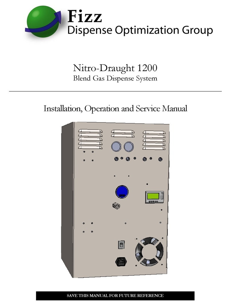
Fizz Nitro-Draught ND0101 Setup guide

Nitro-Draught
Revision 2016
Blend Gas Dispense System
Includes Models ND0101, ND0102, ND0201, ND0202
Installation, Operation and Service Manual
Revision 1.0
SAVE THIS MANUAL FOR FUTURE REFERENCE

CONTENTS
Section 1 –Safety Guidelines & Definitions
Section 2 –Unit Safety Warnings
Section 3 –Unit Description & Features
3.1: Technical Specifications
3.2: Electrical Schematic
Section 4 –Installation & Operation
4.1: Unpacking your Unit
4.2: Powering up your Unit
Section 5 –Maintenance & Replacement Parts
5.1: Recommended Maintenance
5.2: Maintenance Service Kits & Instructions
5.3: Other Replacement Parts
5.4: Manufacturer Maintenance/Service
Section 6 –Troubleshooting
Section 7 –Warranty Information
7.1: Policy
7.2: Claims Process

SECTION 1
Safety guidelines & definitions
SECTION 2
Unit safety warnings
Do not operate the Nitro-Draught unit until the information contained in this document has been read
and understood by all personnel concerned. The unit should be connected to an electrical supply in
accordance with local safety regulations. Ensure that the rating plate corresponds to the supply
voltage. Ensure that the unit is grounded.
Nitrogen (N2) & carbon dioxide (CO2) are not poisonous gases but in a concentrated form present a
risk of asphyxiation. The Nitro-Draught unit produces a small flow of mixed gases that quickly
disperse in the atmosphere. However, do not directly inhale any gases produced by the unit. Refer to
Compressed Gas Association publications for further information.
Before service or maintenance is performed on the Nitro-Draught system, the electrical supply must
be switched off and the main electrical cord disconnected. All personnel handling, using or
maintaining the Nitro-Draught unit must employ safe working practices and observe all relevant local
health and safety regulations.
WARNING: The WARNING symbol draws attention to an operating
procedure or practice that can cause injury if it is not observed or
performed correctly. Do not continue past a WARNING symbol until you
have fully understood or satisfied the indicated conditions.
CAUTION: The CAUTION symbol draws attention to an operating
procedure or practice that can damage the unit if it is not observed or
performed correctly. Do not continue past a CAUTION symbol until you
have completely understood or satisfied the indicated conditions.

SECTION 3
Unit description & features
The Nitro-Draught blend gas dispense system extracts nitrogen (N2) from ambient air, blends it with
carbon dioxide (CO2) and supplies the mixed gas to a draught beer system. As a component of a
properly designed and maintained draught system, the Nitro-Draught assures brewery quality
beverage presentation while it eliminates excessive foaming and wasted beer.
The Nitro-Draught system uses proven Pressure Swing Adsorption (PSA) technology with Carbon
Molecular Sieve (CMS) to separate N2from the atmosphere and store it at a purity level of at least
99.8%. It uses a mechanical blender to combine the N2with CO2from another storage vessel into
CO2/ N2“beer gas” blend ratios, commonly two blends are used, 25% / 75% and 70% / 30%. Blends
can be customized for any application. Pure nitrogen can be withdrawn directly from the storage tank
to use in inert wine dispense equipment.
While in Production Mode, the internal air compressor will cycle on and off on approximately two
minute cycles. Each compression cycle will be followed by an exhaust cycle. At the start of the
exhaust cycle, an audible release of internal air pressure will occur. This compress-exhaust
alternating cycle will continue until the unit fully pressurizes the storage tank. At that point the unit will
move into Economy Mode, and power down all internal components after a few minutes. The Nitro-
Draught will enter into Economy Mode at “Switch Off” tank pressure and then return to Production
Mode when the tank pressure drops to “Switch On” pressure (see section 3.1 Technical
Specifications for settings), as nitrogen is used.
This manual contains the information necessary for the correct use of the Nitro-Draught. Should any
questions arise regarding safe and proper installation, operation or maintenance of the Nitro-Draught
system, contact the supplier before proceeding.
Warning: Ensure that all personnel involved in the installation,
operation and maintenance of the Nitro-Draught system, as well
as those persons who will act as supervisory personnel, have read
and fully understand the instructions before attempting to install,
operate or perform maintenance on the unit.

3.1 Technical specifications
•Model: ND0101, ND0102, ND0201, ND0202
•Dimensions (approximate):
ND0101, ND0102 - Height 24 in/ 600 mm, Width 15 in/ 380 mm, Depth 15 in/ 380 mm
ND0201, ND0202 - Height 28 in/ 710 mm, Width 15 in/ 380 mm, Depth 15 in/ 380 mm
•Weight (approximate):
ND0101, ND0102 - 80 lb/ 36 kg
ND0201, ND0202 - 100 lb/ 45 kg
•Electrical Power Supply: 120 Vac 60 Hz
•Fuse Rating: 10 amps
•Ambient Temperature: 36 to 95ºF (+2 to +35ºC)
•N2Storage Vessel Size: Approx 25 gal/ 95 liters
•Nitrogen Purity: >99.8% (<0.2% oxygen)
•N2Generation Cycle Start/Stop Pressures:
ND0101, ND0201 –Switch Off 100 psig/ 6.2 barg;
Switch On 92psig (6.2 barg)
ND0102, ND0202 - Switch Off 135 psig/ 9.3 barg;
Switch On 128psig (8.8 barg)
•CO2Gas Requirement: 90 –300 psig (6 –20 barg)
•Mixed Blends (CO2 /N2): (25% / 75%) & (70% / 30%)
•Max Blend Outlet Pressure: 60 psig (4.8 barg)
•Inlet and Outlet Bulkhead Ports: 1/4” FNPT

3.2 Electrical Schematic

SECTION 4
Installation & operation
4.1 Unpacking your unit
Remove the items from the box and check for damage. The box contains one Nitro-Draught unit, a
manual, and a power cord. If any of the items are in a damaged condition, request an immediate
inspection by the carrier. If any of the items are missing, please contact Fizz.
4.2 Powering up your unit
Installation quick checklist
1. Unpack and inspect unit
2. Mount unit to a solid and secure surface
3. Plug into suitable electrical outlet
4. Connect unit port “To Storage” to external pressure vessel and start nitrogen production.
Connect a return pressure line from external vessel to unit port “From Storage.
5. Make CO2and blend gas connections
6. Connect to draught and wine dispense system
7. Recheck connections and equipment for proper operation
mmder
Nitrogen To
Storage
Nitrogen From
Storage
CO2Supply
90 –300 psi
Blend Gas
To Kegs
Power Cord
Socket –Contains
Fuses

SECTION 5
Maintenance & replacement parts
5.1 Recommended maintenance
Replacement of the compressor air compressor inlet filter, coalescing filter element and
exhaust silencer should be performed at least every twelve months or more frequently,
depending on environmental conditions. Cooling vents should be cleaned of any dust
accumulation during filter changes. Verify the unit is leak tight before returning to
service.
Before performing maintenance on a Nitro-Draught unit, disconnect the main power supply.
Failure to perform specified service may result in damage to the Nitro-Draught unit and may invalidate
any warranty. Use only genuine parts as supplied by Fizz.
The quality and reliability of the Nitro-Draught unit is maintained through preventive maintenance
performed on a scheduled, regular basis.
Keep a written record of all maintenance activity.
5.2 Maintenance service kits & instructions
Filter Replacement (Kit p/n 83108)
Switch off the electrical power supply before performing any service on a Nitro-Draught unit. Close
the “CO2Inlet” and N2To Storage” isolation valves. Depressurize the system by switching the unit on
again for 20 seconds allowing it to exhaust (and depressurize). Shut the unit off.
Replace the compressor air intake filter element:
1. Lift up tabs on both sides of filter assembly and pull cover off assembly.
2. Pull the used filter element from the housing cap and dispose of the used element.
3. Fit the replacement element by pushing the element, narrow end first, into the bottom of the
assembly.
4. Replace the cover by pressing it down onto bottom piece until it snaps tight.
Replace exhaust silencer:
1. Unscrew used silencer by turning counter clockwise.
2. Replace with new silencer, tightening only finger tight.
Replace the coalescing filter:
1. Make sure the housing is completely depressurized before continuing.
2. Unplug solenoid electrical connector.
3. Unscrew body/bowl of green coalescing filter.
4. Remove the element from the bowl and dispose in accordance with local waste regulations.
5. Carefully remove the new element from the packaging and insert into the bowl by aligning

proper tabs on element until it seats completely into bowl. There is only one proper
orientation. Screw bowl back into filter head until it seats.
compressor air
intake filter element
exhaust silencer
coalescing
filter

5.3 Other replacement parts
97007 Cabinet Cooling Fan
97025 Fuse, 10 amp
97028 Power Cord
80008 Power Switch
80009 Power Socket
58010 Power Supply 24V
80013 Regulator, Blender Manifold
80018 Regulator, Sieve Column Outlet
All parts are available by calling or emailing Fizz.
5.4 Factory repair and refurbishment
Fizz will service any unit (whether within warranty period or not) at the request of the customer.
Authorization must be obtained from Fizz prior to shipping any equipment to Fizz facilities. The model
and serial number of the unit must be provided in order to process the return. The customer returning
the goods is responsible for all freight, proper packing, and any damage incurred during shipment of
the goods back to Fizz.
SECTION 6
Troubleshooting
Service or maintenance on the Nitro-Draught should be performed only by Fizz trained and
authorized professional service agents who are familiar with mixed gas pressure systems and all
pertinent safety and service procedures. Fizz recommends the use of Fizz approved replacement
parts.
Symptom –Low pressure in nitrogen storage tank
Low pressure in the nitrogen storage tank may have been caused by excessive demand from
the downstream system, such as a leaking keg coupler. Close the “To Storage” valve on the tank to
allow the generator to build pressure in this line (tank will be isolated). Pressure in the “To Storage”
line will be shown on the N2pressure gauge as well as the controller display screen. If the pressure
increases to “Switch Off” pressure and holds without leaking down, the unit is operating properly. The
storage tank and downstream system should be checked for leaks. Allow the generator time to refill
the storage tank.
If the “To Storage” line pressure does not increase after 3-4 compression cycles, the unit will
need to be serviced by a trained technician.
Symptom –Low blend gas pressure
Low blend gas pressure is usually caused by a lack of N2or CO2pressure coming into the unit.
Verify both of these gases are being adequately supplied to the Nitro-Draught unit.

SECTION 7
Warranty information
7.1 Warranty policy
Fizz Dispense Optimization Group, LLC warrants to the Purchaser the Nitro-Draught blend gas
system shall be free from any defects in workership and materials for 30 months from the date of
shipment from Fizz. Purchaser agrees that as a pre-condition to any Fizz liability hereunder,
Purchaser or its appointed agents shall fully inspect all goods immediately upon delivery and shall
give Fizz written notice of any claim or purported defect within ten (10) days after discovery of such
defect.
Use of the Nitro-Draught system without the recommended inlet air quality or genuine parts will
expressly invalidate the warranty.
As a further pre-condition to any Fizz liability hereunder, parts replacement must be supplied by a
Fizz approved service company. Fizz may elect to repair or replace any defective component or part
thereof which proves to be defective, or to refund the purchase price paid by the original Purchaser.
Fizz shall not be liable for defects caused by the effects of normal wear and tear, erosion, corrosion,
fire, explosion, misuse, or unauthorized modification.
Alterations or repair by others than those designated and approved by Fizz or operation of such
equipment in a manner inconsistent with Fizz accepted practices and all operating instructions,
unless pre-authorized in writing by Fizz, shall void this Warranty.
Fizz’s sole and exclusive liability under this Warranty is to the Purchaser and shall not exceed the
lesser of the cost of repair parts, cost of replacement, or refund of the net purchase price paid by the
original Purchaser. Any accessories, parts and equipment supplied by Fizz but not manufactured by
Fizz shall carry whatever warranty the manufacturer has given to Fizz providing it is possible for Fizz
to pass on such warranty to the customer.
Fizz is not liable for any losses (including CO2 or beer), back up gas supply, damages, or costs
of delays, including incidental or consequential damages. These include lost profits and the
cost of the installation or removal of any products or parts, the installation of replacement
products, and any inspection, testing, or redesign caused by any defect or by the repair or
replacement of products arising from a defect in any product. Fizz specifically makes no
warranties or guarantees, expressed or implied, including the warranties of merchantability or
fitness for a particular purpose or use, other than those warranties expressed herein.

7.2 Claims process
All warranty claims must be previously authorized in writing by Fizz Dispense Optimization Group,
LLC.
Electronic approval may be obtained by contacting Fizz Technical / Customer Services at:
-Telephone: 800-253-6610
-Fax: 678-792-7784
Or by writing to:
Fizz Dispense Optimization Group, LLC
PO Box 1003
Adairsville GA 30103 USA
Authorization must be obtained from Fizz prior to shipping any equipment to Fizz facilities.
The model and serial number of the unit must be provided in order to process the return. If approved,
a Return Material Authorization (RMA) number will be provided. The RMA number must be
prominently indicated on the packing slip and any packaging that accompanies the goods being
returned. The customer returning the goods is responsible for all freight, proper packing, and any
damage incurred during shipment of the goods back to Fizz.
Shipments to:
Fizz Dispense Optimization Group
1 Johnson Street, Bldg 120
Cartersville GA 30120 USA

This manual suits for next models
3
Table of contents
Other Fizz Dispenser manuals
Popular Dispenser manuals by other brands

Graco
Graco PrecisionSwirl 243402 Instructions-parts list

lancer
lancer FS 30 instruction sheet

Chicco
Chicco 00007657000000 instructions

Silver King
Silver King SK2SB Technical manual and replacement parts list

Ice-O-Matic
Ice-O-Matic Hotel Dispenser CD 40022 Specifications

Craftsman
Craftsman CMCE600 instruction manual