5
Fläkt Woods 9191 GB 2015.09.24 Specifications are subject to alteration without notice
Installation and maintenance instructions
Fläkt Woods PM-Motor
With suPPlied FC 102 FrequenCy Converter
[Status]
indicates the status of the frequency converter and/or the motor.
3 different readouts can be chosen by pressing the [Status] key:
5 line readouts, 4 line readouts or Smart Logic Control.
Use [Status] for selecting the mode of display or for changing
back to Display mode from either the Quick Menu mode, the Main
Menu mode or Alarm mode. Also use the [Status] key to toggle
single or double read-out mode.
[Quick Menu]
allows quick set-up of the frequency converter. The most com-
mon VLT HVAC Drive functions can be programmed here.
The [Quick Menu] consists of:
• My Personal Menu
• Quick Set-up
• Function Set-up
• Changes Made
• Loggings
The Function set-up provides quick and easy access to all
parameters required for the majority of VLT HVAC Amongst
other features it also includes parameters for selecting which
variables to display on the LCP, digital preset speeds, scaling
of analog references, closed loop single zone and multizone
applications and specific functions related to Fans, etc.
The Quick Menu parameters can be accessed immediately
unless a password has been created via par. 0-60 Main Menu
Password, par. 0-61 Access to Main Menu w/o Password,
par. 0-65 Personal Menu Password or par. 0-66 Access to
Personal Menu w/o Password.
It is possible to switch directly between Quick Menu mode
and Main Menu mode.
[Main Menu]
is used for programming all parameters. The Main Menu para-
meters can be accessed immediately unless a password has
been created via par. 0-60 Main Menu Password, par. 0-61
Access to Main Menu w/o Password, par. 0-65 Personal Menu
assword or par. 0-66 Access to Personal Menu w/o Password.
For the majority of VLT HVAC Drive applications it is not neces-
sary to access the Main Menu parameters but instead the Quick
Menu, Quick Set-up and Function Set-up provides the simplest
and quickest access to the typical required parameters. It is
possible to switch directly between Main Menu mode
and Quick Menu mode.
Parameter shortcut can be carried out by pressing down
the [Main Menu] key for 3 seconds. The parameter shortcut
allows direct access to any parameter.
[Alarm Log]
displays an Alarm list of the ten latest alarms (numbered
A1-A10). To obtain additional details about an alarm, use the
arrow keys to manoeuvre to the alarm number and press [OK].
Information is displayed about the condition of the frequency
converter before it enters the alarm mode.
The Alarm log button on the LCP allows access to both
Alarm log and Maintenance log.
[Back]
reverts to the previous step or layer in the navigation structure.
[Cancel]
last change or command will be cancelled as long as the
display has not been changed.
[Info]
displays information about a command, parameter, or function
in any display window. [Info] provides detailed information
when needed.
Exit Info mode by pressing either [Info],[Back], or [Cancel].
Navigation Keys
The four navigation arrows are used to navigate between the
different choices available in [Quick Menu], [Main Menu] and
[Alarm Log].
Use the keys to move the cursor.
[OK] is used for choosing a parameter marked by the cursor
and for enabling the change of a parameter.
Operation Keys for local control are found at the bottom
of the control panel.
• Yellow LED/Warn.: Indicates a warning.
• Flashing Red LED/Alarm: Indicates an alarm.
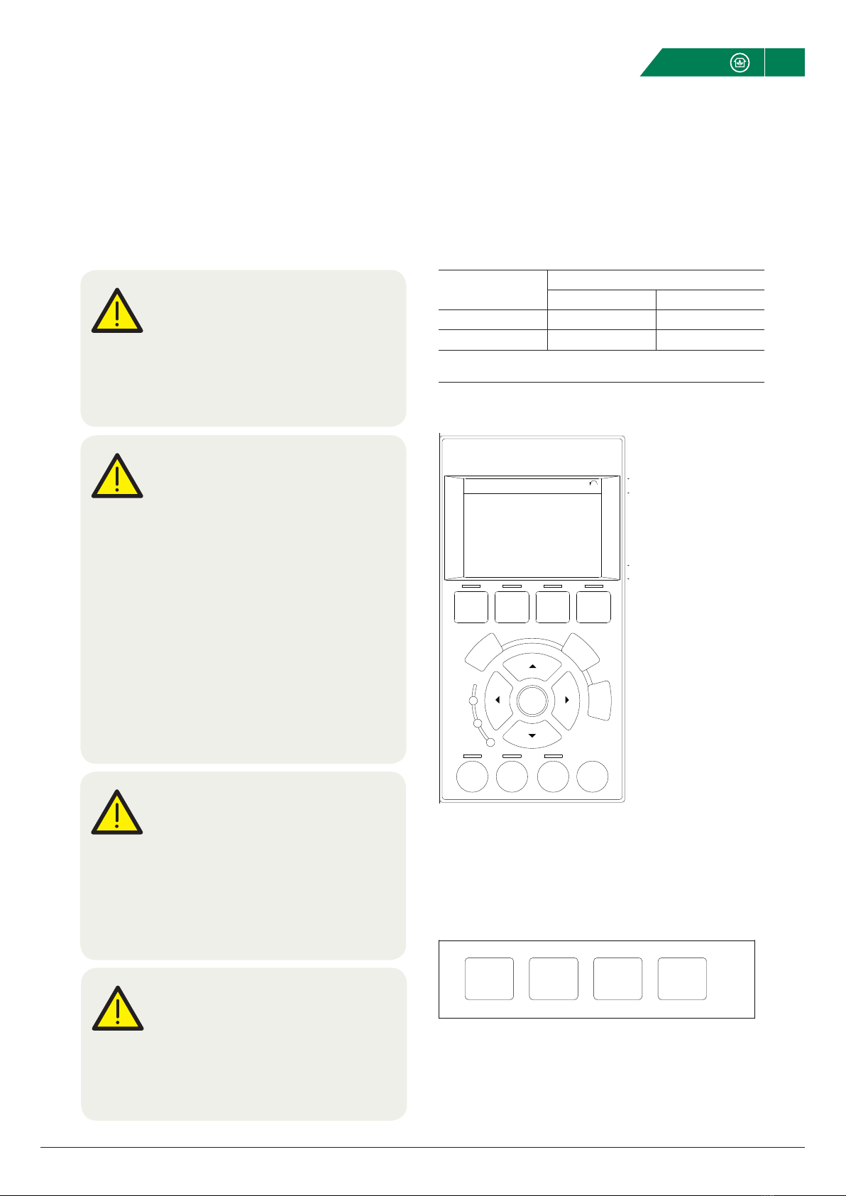
Menu keys
The menu keys are divided into functions. The keys below the display
and indicator lamps are used for parameter set-up, including choice of
display indication during normal operation.
130BP045.10
Status Quick
Menu
Main
Menu
Alarm
Log
[Status]
indicates the status of the frequency converter and/or the motor. 3 dif-
ferent readouts can be chosen by pressing the [Status] key:
5 line readouts, 4 line readouts or Smart Logic Control.
Use [Status] for selecting the mode of display or for changing back to
Display mode from either the Quick Menu mode, the Main Menu mode
or Alarm mode. Also use the [Status] key to toggle single or double
read-out mode.
[Quick Menu]
allows quick set-up of the frequency converter. The most common
VLT HVAC Drive functions can be programmed here.
The [Quick Menu] consists of:
- My Personal Menu
- Quick Set-up
- Function Set-up
- Changes Made
- Loggings
The Function set-up provides quick and easy access to all parameters
required for the majority of VLT HVAC Drive applications including most
VAV and CAV supply and return fans, cooling tower fans, Primary, Sec-
ondary and Condenser Water Pumps and other pump, fan and com-
pressor applications. Amongst other features it also includes parame-
ters for selecting which variables to display on the LCP, digital preset
speeds, scaling of analog references, closed loop single zone and multi-
zone applications and specific functions related to Fans, Pumps and
Compressors.
The Quick Menu parameters can be accessed immediately unless a
password has been created via par. 0-60
Main Menu Password
,
par. 0-61
Access to Main Menu w/o Password
, par. 0-65
Personal Menu
Password
or par. 0-66
Access to Personal Menu w/o Password
.
It is possible to switch directly between Quick Menu mode and Main
Menu mode.
[Main Menu]
is used for programming all parameters. The Main Menu parameters
can be accessed immediately unless a password has been created via
par. 0-60
Main Menu Password
, par. 0-61
Access to Main Menu w/o
Password
, par. 0-65
Personal Menu Password
or par. 0-66
Access to
Personal Menu w/o Password
. For the majority of VLT HVAC Drive ap-
plications it is not necessary to access the Main Menu parameters but
instead the Quick Menu, Quick Set-up and Function Set-up provides the
simplest and quickest access to the typical required parameters.
It is possible to switch directly between Main Menu mode and Quick
Menu mode.
Parameter shortcut can be carried out by pressing down the [Main
Menu] key for 3 seconds. The parameter shortcut allows direct access
to any parameter.
[Alarm Log]
displays an Alarm list of the ten latest alarms (numbered A1-A10). To
obtain additional details about an alarm, use the arrow keys to ma-
noeuvre to the alarm number and press [OK]. Information is displayed
about the condition of the frequency converter before it enters the
alarm mode.
The Alarm log button on the LCP allows access to both Alarm log and
Maintenance log.
[Back]
reverts to the previous step or layer in the navigation structure.
[Cancel]
last change or command will be cancelled as long as the display has
not been changed.
[Info]
displays information about a command, parameter, or function in any
display window. [Info] provides detailed information when needed.
Exit Info mode by pressing either [Info], [Back], or [Cancel].
B
a
c
k
C
a
n
c
e
l
I
n
f
o
Navigation Keys
The four navigation arrows are used to navigate between the different
choices available in [Quick Menu], [Main Menu] and [Alarm Log].
Use the keys to move the cursor.
[OK] is used for choosing a parameter marked by the cursor and for
enabling the change of a parameter.
VLT HVAC Drive High Power Operating In-
structions 5 How to Operate the Frequency Converter
MG.11.F3.02 - VLT® is a registered Danfoss trademark 85
5
OK
Back
ofnI
Warm
Alarm
On
Cancel
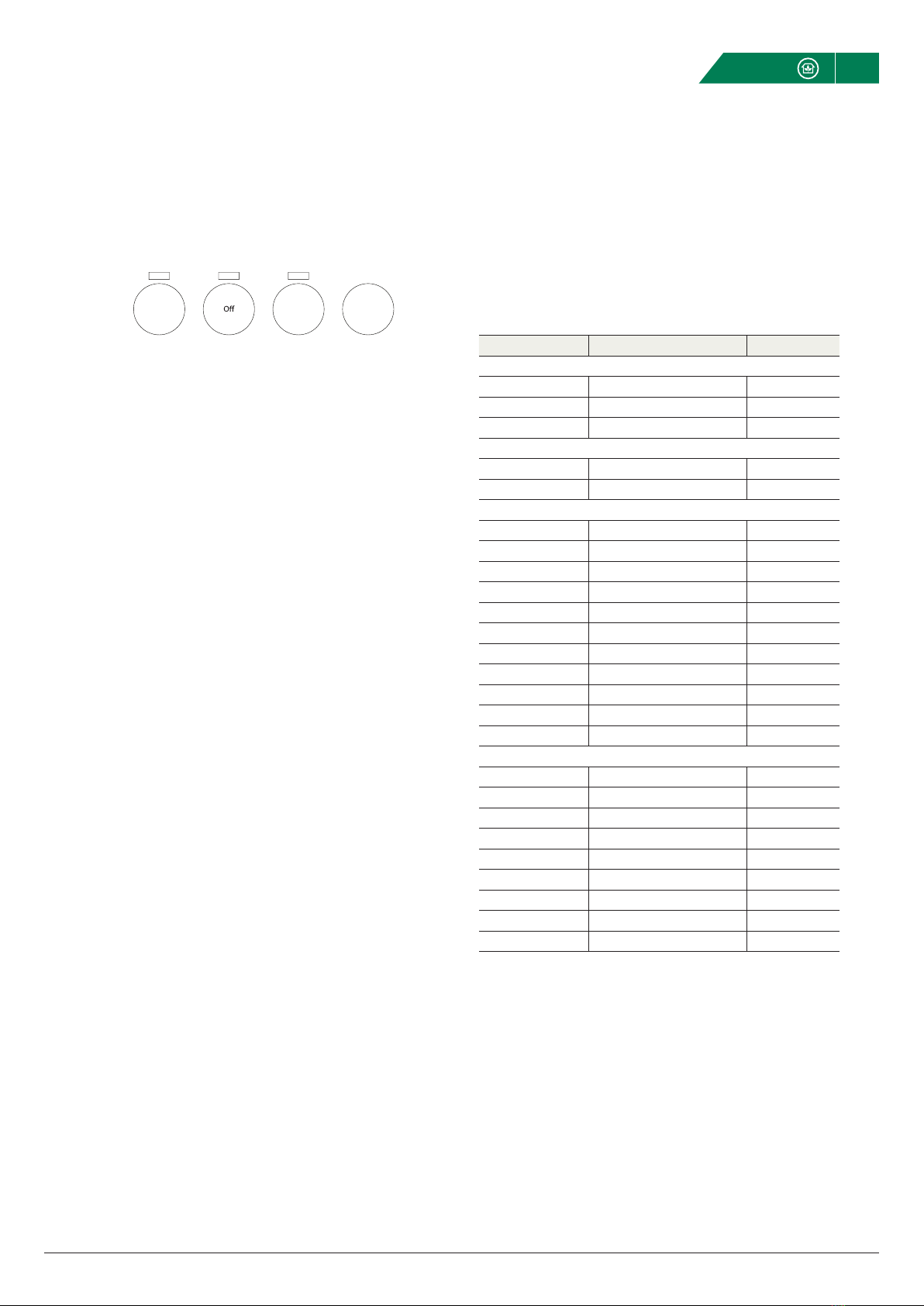
Operation Keys for local control are found at the bottom of the con-
trol panel.
Hand
on
Auto
on Reset
[Hand On]
enables control of the frequency converter via the GLCP. [Hand On] al-
so starts the motor, and it is now possible to enter the motor speed da-
ta by means of the arrow keys. The key can be selected as
Enable
[1]
or
Disable
[0] via par. 0-40
[Hand on] Key on LCP
.
The following control signals will still be active when [Hand On] is acti-
vated:
•[Hand on] - [Off] - [Auto on]
•Reset
•Coasting stop inverse
•Reversing
•Set-up select lsb - Set-up select msb
•Stop command from serial communication
•Quick stop
•DC brake
NB!
External stop signals activated by means of control
signals or a serial bus will override a “start” com-
mand via the LCP.
[Off]
stops the connected motor. The key can be selected as Enabled [1] or
Disabled [0] via par. 0-41
[Off] Key on LCP
. If no external stop function
is selected and the [Off] key is inactive the motor can only be stopped
by disconnecting the mains supply.
[Auto on]
enables the frequency converter to be controlled via the control termi-
nals and/or serial communication. When a start signal is applied on the
control terminals and/or the bus, the frequency converter will start. The
key can be selected as Enabled [1] or Disabled [0] via par. 0-42
[Auto
on] Key on LCP
.
NB!
An active HAND-OFF-AUTO signal via the digital in-
puts has higher priority than the control keys [Hand
on] – [Auto on].
[Reset]
is used for resetting the frequency converter after an alarm (trip). It
can be selected as
Enable
[1] or
Disable
[0] via par. 0-43
[Reset] Key
on LCP
.
The parameter shortcut can be carried out by holding down the [Main
Menu] key for 3 seconds. The parameter shortcut allows direct access
to any parameter.
5.1.3 RS-485 Bus Connection
One or more frequency converters can be connected to a controller (or
master) using the RS-485 standard interface. Terminal 68 is connected
to the P signal (TX+, RX+), while terminal 69 is connected to the N sig-
nal (TX-,RX-).
If more than one frequency converter is connected to a master, use
parallel connections.
130BA060.11
68 69 68 69 68 69
RS 485
RS 232
USB
+
-
Illustration 5.1: Connection example.
5 How to Operate the Frequency Converter
VLT HVAC Drive High Power Operating In-
structions
86 MG.11.F3.02 - VLT®is a registered Danfoss trademark