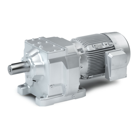
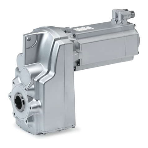
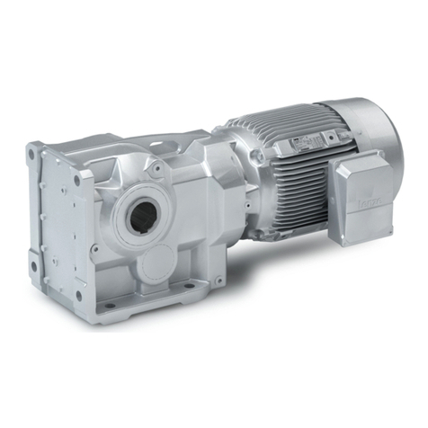
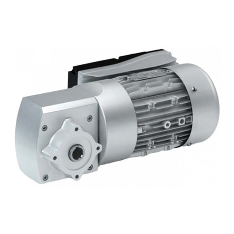
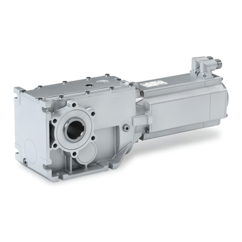
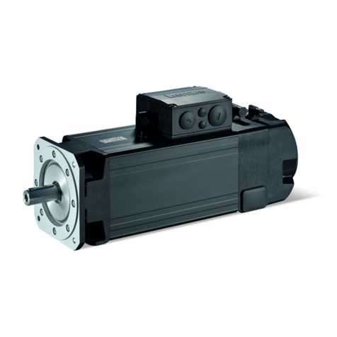
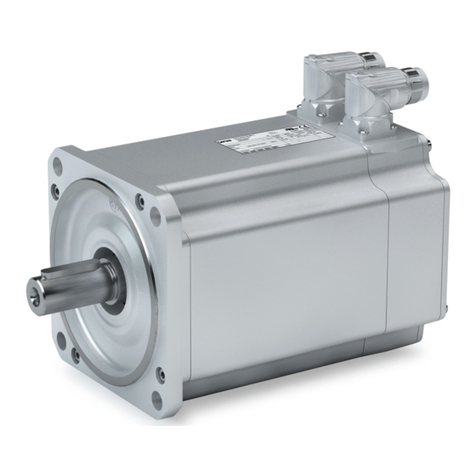
Lenze Smart Motor m300 Technical manual

Three-phase AC motors
Lenze Smart motor m300
Project planning EN


Contents
About this document 5
Document descripon 5
Further documents 5
Notaons and convenons 6
Product informaon 7
Product descripon 7
Idencaon of the products 10
Features 10
The modular system 11
Mounng posions 12
Informaon on project planning 13
Safety instrucons 13
Basic safety instrucons 13
Applicaon as directed 13
Residual hazards 14
Drive dimensioning 15
Final conguraon 17
Surface and corrosion protecon 18
Informaon on mechanical installaon 19
Important notes 19
Transport 19
Installaon 19
Informaon on electrical installaon 20
Important notes 20
Preparaon 20
Connecon according to EN 21
Connecon according to cULus 24
Technical data 28
Notes regarding the given data 28
Standards and operang condions 29
Conformies and approvals 29
Protecon of persons and device protecon 30
EMC data 30
Environmental condions 31
Electrical supply condions 31
Radial forces and axial forces 32
Rated data 33
Ecodesign Direcve 34
Torque characteriscs 35
Dimensions 36
Basic dimensions 36
Contents
3

Product extensions 42
Motor connecon 42
Connecon via terminal box 42
Connecon via QUICKON V2 connector 42
Connecon via M15 connector 43
Connecon via M12 connector 44
Brakes 45
Spring-applied holding brake 46
Brake resistors 48
Accessories 49
NFC adapter 49
QUICKON connector 50
UMCLN_SGG_100181 51
Purchase order 52
Notes on ordering 52
Product codes 53
Environmental notes and recycling 54
Appendix 55
Good to know 55
Operang modes of the motor 55
Enclosures 56
Contents
4

About this document
Document descripon
This document addresses to all persons who want to carry out any conguraons with the
products described.
The data and informaon compiled in this document serve to support you in the dimensioning
and selecon processes and in carrying out the electrical and mechanical installaon. You will
receive informaon regarding product extensions and accessories.
•The document includes safety instrucons which must be observed.
•All persons working on and with the drives must have the documentaon at hand during
work and observe the informaon and notes relevant for it.
•The documentaon must always be complete and in a perfectly readable state.
Further documents
Informaon and tools with regard to the Lenze products can be found on the
Internet:
www.Lenze.com à Downloads
About this document
Document descripon
5

Notaons and convenons
This document uses the following convenons to disnguish dierent types of informaon:
Numbers
Decimal separator Point In general, the decimal point is used.
Example: 1 234.56
Warning
UL warning UL Are used in English and French.
UR warning UR
Text
Programs » « Soware
Example: »Engineer«, »EASY Starter«
Icons
Page reference ¶Reference to another page with addional informaon
Example: ¶ 16 = see page 16
Documentaon reference ,Reference to another documentaon with addional informaon
Example: , EDKxxx = see documentaon EDKxxx
Layout of the safety instrucons
DANGER!
Indicates an extremely hazardous situaon. Failure to comply with this instrucon will result
in severe irreparable injury and even death.
WARNING!
Indicates an extremely hazardous situaon. Failure to comply with this instrucon may result
in severe irreparable injury and even death.
CAUTION!
Indicates a hazardous situaon. Failure to comply with this instrucon may result in slight to
medium injury.
NOTICE
Indicates a material hazard. Failure to comply with this instrucon may result in material
damage.
About this document
Notaons and convenons
6

Product informaon
Product descripon
The new freedom in moon for engineers. Lenze Smart Products reduce the number of
dierent drives by up to 70 %. Without contactor and starter, with freely adjustable xed
speeds and many integrated funcons for technical material-handling applicaons. The Lenze
Smart motor also fulls the highest requirements regarding energy eciency and can be
conveniently operated by means of a smart phone.
Reducon in the number of variants made easy
Before now, dierent output speeds (e. g. for dierent conveying speeds) were enabled by
dierent gearbox raos or, in the case of very large dierences, by means of the number of
pole pairs of the motors. This led to a large number of dierent drive variants..
Things are dierent with the Lenze Smart Products: Due to the possibility of freely adjusng
the motor speed within a range from 500 – 2600 rpm, very dierent speeds can be enabled
with one single drive variant The cost and eort involved in design, selecon, procurement
and storage are thus reduced considerably.
Highlights
•Ecient and usable worldwide
•Usable in all mounng posions, reduces number of variants
•Freely adjustable speed reduces the number of dierent drives
•Integrated so start funcon
•Less wiring thanks to electronic contactor and motor protecon funcon
•Excellent energy eciency
•Can be operated with an NFC-capable smartphone and Lenze app
•Brake control unit oponal for low-wear brake control
Applicaon ranges
•Conveying and travelling drives
Product informaon
Product descripon
7

Easy adjustment
NFC technology (NFC = Near Field Communicaon) is used to adapt the Lenze Smart Products
to the applicaon as well as for diagnoscs). The drive can be adjusted very easily without
opening the terminal box. without voltage supply and without me-consuming addressing.
Only an NFC-capable Android smartphone or the Lenze NFC adapter for PCs is needed as a
tool. The data can therefore be read and wrien when the drive is in a de-energised state –
via password protecon, of course.
Data that can be set
•Name of data record (e. g. the designaon of the drive in your documentaon)
•Speed and rotang direcon 1 (also controllable without digital inputs)
•Speed and rotang direcon 2-5 (controllable by means of digital inputs)
•Acceleraon me
•Deceleraon me
•Energy-saving funcon
Readable data
•Idencaon data (Lenze material number and serial number, type designaon, soware
version)
•Error messages
•Operang and power-on hours
Adjustment by means of a smartphone
The Lenze Smart Products can be adjusted with an Android smartphone. The corresponding
app in German and English can be obtained from www.Lenze.com or the Google Store. For
convenience, the data records created can be archived on the smartphone and repeatedly
transferred to the Lenze Smart Products for dierent applicaons.
Product informaon
Product descripon
8

Adjusng with a PC
With the »EASY Starter« engineering tool (expanded version, »EASY Advanced«“ or »Engineer
HighLevel« soware licence needed) can be used to adjust the Lenze Smart Products. The
relevant version can be easily downloaded from hp://www.lenze.com . As the sengs are
very simple and clear, there is an easy-to-use dialog box, which can be opened directly via the
navigator. The corresponding buon is directly accessible in the navigaon bar. Analogously to
other product sengs, the parameter values can be archived.
Starng and stopping smoothly and gently
An acceleraon ramp and – in contrast to a convenonal starter – a deceleraon ramp can be
set for Lenze Smart Products. This ensures that the conveyed material is handled in a dened
and jerk-free manner..
Contactor and motor protecon funcons integrated
The Lenze Smart Products can be started and stopped by mean of digital inputs. It is also
possible to switch between dierent speeds and rotang direcons. Up to 5 dierent speed
modes (e. g. creep speed and normal speed in both direcons as well as stopping) can be used
for a motor. Reversing-contactor changes and pole changes are thus a thing of the past.
In addion, motor-protecons devices are not needed as monitoring of temperature, short
circuits, earth faults and phase failures has already been integrated.
Easy installaon
Connecon takes place completely from the outside by means of connectors.
The Lenze Smart Products come with an especially clever connecng technology – Phoenix
Contact QUICKON. Electrical installaon is therefore very easy without special tools and
requires less than one minute.
In addion to the QUICKON connector, the M15 connecon customary on the market is
available.
As a standard feature, the digital inputs and outputs are connected at M12 sockets of the type
currently available on the market.
Already exisng signal cables can oen be reused.
Worldwide and ecient
The drive can be used worldwide:
•In all 3-phase networks with a supply voltage of 400 ... 480 V and a mains frequency of
50 ... 60 Hz
•At ambient temperatures of -30 ... +40 °C
•Is suitable for many approvals
The Lenze Smart Motor fulls the requirements as described in the highest eciency
requirement for IES2.
If very lile torque is needed in the paral-load operaonal range, the integrated energy
saving funcon can be used to opmize the energy absorpon of the drive.
Product informaon
Product descripon
9
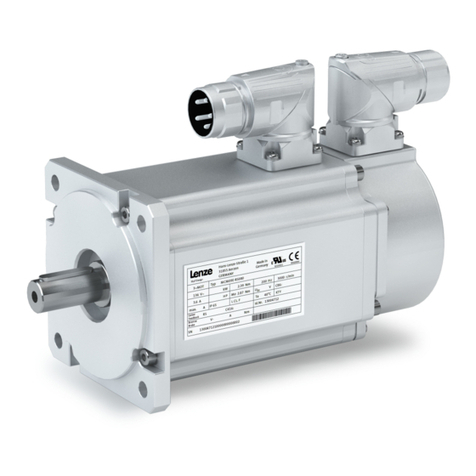
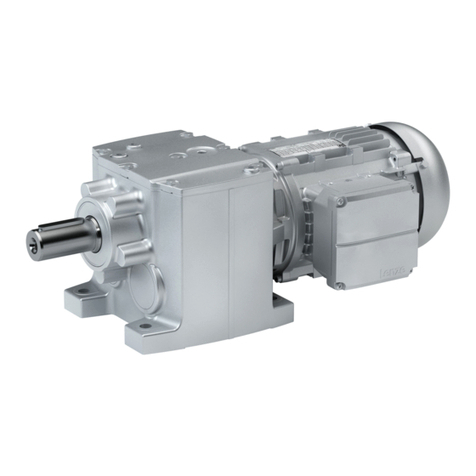
Applicaon examples
Roller conveyors with belt ejector Belt conveyors
Idencaon of the products
Product name of the motor
Product series Type Size Overall length Number of pole
pairs
Motor
MSEMA
XX
(without built-on
accessories)
063
-
4
2 (4-pole)
MSEMAXX063-42
080 3 MSEMAXX080-32
BR
(with brake)
063 4 MSEMABR063-42
080 3 MSEMABR080-32
Features
The following gure provides an overview of the elements and connecons on the product.
Their posion, size and appearance may vary.
Connection of spring-applied brake
Mains connection
Control terminal
Brake resistor connection
(prewired upon delivery)
X5
External
X4
Internal brake resistor
PE
by means of Android smartphone
by means of PC via NFC adapter
Adjustment of speeds
M12 connector
X1, X2
In the terminal box
QUICKON V2-connector
M15-connector
X3
Foot (B3)
Flange (B5) with through holes
Flange (B14) with threaded holes
External brake resistor
Standard
LongLife
Manual release lever
Spring-applied brake
Integral fan
Cooling
Type
Product informaon
Idencaon of the products
10

The modular system
Values printed in bold are standard designs. Values that are not printed in bold
are potenal extensions, some of them including a surcharge.
Motor MSEMA☐☐063-42 MSEMA☐☐080-32
Technical data
Max. torque Nm 7 20
Rated torque Nm 1.75 5.0
Speed seng range rpm -2600 ... -500 / 0 / 500 ... 2600
Dimensions
Design B3/B14/B5
Solid sha with featherkey mm 11 x 23 19 x 40
Output ange mm FT75/FF115 FT100/FT130/FF165
Spring-applied brake
Type Without
Standard
Long-life
Without/with manual release lever
Brake resistor Without
Integrated
External
Cooling Integral fan
Monitoring and protecve
measures
Short circuit (to a limited extent), error acknowledgement
Earth fault (to a limited extent), error acknowledgement necessary
Overvoltage
Overcurrent
Motor overtemperature
Mains phase failure
Motor stalling
Motor connecon
Power connecon Terminal box
QUICKON V2 connector
M15 connector
Control terminal M12 connector
Surface and corrosion protecon Without
Dierent types of OKS
Color Unpainted
Primed/RAL colors
Product informaon
The modular system
11

Mounng posions
Posions of the connecons
Mains connecon Control terminal
Cable gland for terminal box
QUICKON V2 connector
M15 connector
M12 connector
E
E
Posion of the manual release lever
Product informaon
The modular system
Mounng posions
12

Informaon on project planning
Safety instrucons
Basic safety instrucons
Disregarding the following basic safety instrucons and safety informaon may lead to severe
personal injury and damage to property!
•Only use the product as directed.
•Never commission the product in the event of visible damage.
•Never modify the product technically.
•Never commission the product before assembly has been completed.
•Never operate the product without the required covers.
•Connect/disconnect all pluggable connecons only in deenergized condion!
•Only remove the product from the installaon in the deenergized state.
•The product can – depending on their degree of protecon – have live, movable or
rotang parts during or aer operaon. Surfaces can be hot.
•Observe all specicaons of the corresponding documentaon supplied. This is the
condion for safe and trouble-free operaon and the achievement of the specied
product features.
•The procedural notes and circuit details given in the associated documentaon are
suggesons and their transferability to the respecve applicaon has to be checked. The
manufacturer of the product does not take responsibility for the suitability of the process
and circuit proposals.
•All work with and on the product may only be carried out by qualied personnel.
IEC 60364 and CENELEC HD 384 dene the qualicaons of these persons:
-They are familiar with installing, mounng, commissioning, and operang the product.
-They have the corresponding qualicaons for their work.
-They know and can apply all regulaons for the prevenon of accidents, direcves, and
laws applicable at the place of use.
Applicaon as directed
•The product is a professional equipment intended for use by trades, specic professions or
industry and not for sale to the general public. IEC 60050 [IEV 161-05-05]
•To prevent personal injury and damage to property, higher-level safety and protecon
systems must be used!
•All transport locks must be removed.
•Mounted eye bolts on the motor are not suitable for transporng geared motors.
•The product may only be operated under the specied operang condions and in the
specied mounng posions.
•The product is suitable for horizontal conveying only.
•The product may only be operated from the mains.
•Built-in brakes must not be used as safety brakes.
•The product must not be operated in private areas, in potenally explosive atmospheres
and in areas with harmful gases, oils, acids and radiaon.
Informaon on project planning
Safety instrucons
Basic safety instrucons
13

Residual hazards
Even if notes given are taken into consideraon and protecve measures are implemented,
the occurrence of residual risks cannot be fully prevented.
The user must take the residual hazards menoned into consideraon in the risk assessment
for his/her machine/system.
If the above is disregarded, this can lead to severe injuries to persons and damage to
property!
Product
Observe the warning labels on the product!
Dangerous electrical voltage:
Before working on the product, make sure there is no voltage applied to the power terminals!
Aer mains disconnecon, the power terminals will sll carry the hazardous electrical voltage for the me given next to the
symbol!
Electrostac sensive devices:
Before working on the product, the sta must ensure to be free of electrostac charge!
High leakage current:
Carry out xed installaon and PE connecon in compliance with:
EN IEC 61800−5−1 / EN IEC 60204−1
Hot surface:
Use personal protecve equipment or wait unl the device has cooled down!
Protecon of persons
•The power terminals may carry voltage in the switched-o state or when the motor is
stopped.
-Before working, check whether all power terminals are deenergized.
•Voltages may occur on the drive components (e.g. capacive, caused by inverter supply).
-Careful earthing in the marked posions of the components must be carried out.
•There is a risk of burns from hot surfaces.
-Provide protecon against accidental contact.
-Use personal protecve equipment or wait unl the device has cooled down.
-Prevent contact with ammable substances.
•There is a risk of injury due to rotang parts.
-Before working on the drive system, ensure that the motor is at a standsll.
•There is a risk of accidental start-up or electric shock.
Motor protecon
•Parameterize the product so that it will be switched o aer some seconds of operaon
with I > IN , especially if there is a risk of blocking.
-The installed overload protecon does not prevent an overload under any condions.
•The fuses are no motor protecon.
-Use a current-dependent motor protecon switch.
-Use the built-in temperature sensors.
•Too high torques cause a fracon of the motor sha.
-The maximum torques according to catalog must not be exceeded.
•Lateral forces on the motor sha are possible.
-Align the shas of motor and driven machine exactly to each other.
Informaon on project planning
Safety instrucons
Residual hazards
14

Drive dimensioning
In order to carry out an accurate drive dimensioning process, you can use our conguring
soware, the »Drive Soluon Designer«.
With the «Drive Soluon Designer«, you can design the drive both quickly and to a high
quality. The soware contains profound and proven experse with regard to drive applicaons
and mechatronic drive components.
Please get in touch with your Lenze representave.
Workow
Mains operaon
Check operang condions
Dene required input variables
Determine correcon factor
Determine motor frame size on the basis of the forces
Calculate necessary output torque
Determine motor on the basis of the obtained data
Final conguraon
Check operang condions
Check
Approvals
Conformies
Supply voltage
Degree of protecon
Ambient temperature
Surface protecon
4Standards and operang condions ^ 29
4Surface and corrosion protecon ^ 18
Dene required input variables
Necessary input variables Note Symbol Unit
Ambient temperature TV°C
Site altude Amsl H m
Radial force Frad rated
axial force Fax rated
Transmission element at the output Gear wheels, sprockets …
Eecve diameter of the transmission element dwmm
Load torque ML,max Nm
Load speed nL,max rpm
Determine correcon factor
Ambient temperature TU°C ≤ 40
Correcon factor kTU 1
Informaon on project planning
Drive dimensioning
15

Installaon height amsl
≤ 1000 m ≤ 2000 m ≤ 3000 m ≤ 4000 m
Correcon factor
kHkHkHkH
1 0.95 .90 .85
Determine product on the basis of the forces
Transmission element Gear wheels Sprockets Toothed belt pulleys Narrow V-belt
( depending on the
preloading)
( depending on the
preloading)
Addional radial force factor fz
≥ 17 teeth = 1.0 ≥ 20 teeth = 1.0 With belt ghtener= 2.0 -
2.5
1.5 - 2.0
< 17 teeth = 1.15 < 20 teeth = 1.25 Without belt ghtener= 2.5
- 3.0
< 13 teeth = 1.4
Calculaon Check
Radial force Frad N
´
= ´ L,max z
rad
M f
F 2000 dw
Frad ≤ Frad,max
Axial force Fax N Fax ≤ Fax,max
dw Eecve diameter of transmission element
4Radial forces and axial forces ^ 32
Calculate output torque
Calculaon
Necessary output torque MNN
m
³
´
L,max
NH TU
M
Mk k
Determine motor on the basis of the data obtained from the rated data
Selecon table Check
Output speed nNrpm nL,max≈ nN
Output torque MNNm ML,max≤ MN
4Rated data ^ 33
Informaon on project planning
Drive dimensioning
16

Final conguraon
Check and dene connecon dimensions
Output sha
Output ange
Select product extensions and accessories Brake
NFC adapter
QUICKON connector
M15 connector
More informaon about the nal conguraon:
4The modular system ^ 11
4Product extensions ^ 42
4Accessories ^ 49
Parameters that can be preset by Lenze
The parameters marked with "order-dependent" in the standard seng can be
preset order-related by Lenze.
Standard sengs
Parameter Value Comment
Name Delivery Seng range
Parameter set name --- [text] File name of the parameter set without le
extension *.lsm
Output speed 1 depending on the order [-2600/i ... -500/i] rpm
[0] rpm
[500/i ... 2600/i] rpm
CCW rotaon: < 0 rpm
STOP: 0 rpm
CW rotaon: > 0 rpm
Lenze Smart Motor with gearbox: The rao i is
taken into account when calculang the output
speed.
Output speed 2
Output speed 3
Output speed 4
Output speed 5
Acceleraon me [0.0 ... 20.0] s
nmax
t
Acceleraon me t1 of the ramp generator from
0 rpm to nmax [2600/i] rpm
Deceleraon me Deceleraon me t2 of the ramp generator from
nmax [2600/i] rpm to 0 rpm
Energy-saving funcon [O] Opmized for:
•High dynamic performance
•Maximum starng torque and torque
•High speed accuracy
[On] Reduced energy absorpon in paral load
operaonal range.
Approx. 50 % of the maximum starng torque is
available.
Informaon on project planning
Final conguraon
17

Surface and corrosion protecon
Depending on the ambient condions, the surface and corrosion protecon system (called
OKS) oers tailor-made soluons for opmum protecon.
Various surface coangs ensure reliable funconing even at high air humidity, in outdoor
installaons, or in the presence of atmospheric contaminaon. Any color from the "RAL
Classic" collecon can be chosen for the top coat.
For indoor installaon in buildings and if no special corrosion protecon is required, the
products are also available unpainted (without surface and corrosion protecon system).
Surface and corrosion
protecon (called OKS)
Applicaons Type
without OKS (unpainted) •Indoor installaon, no special corrosion protecon necessary
•Painng by customer
Standard
OKS-G (primed) •Dependent on subsequent top coat applied Oponal
OKS-S (small) •Standard applicaons
•Internal installaon in heated buildings
•Air humidity up to 90%
OKS-M (medium) •Internal installaon in non-heated buildings
•Covered, protected external installaon
•Air humidity up to 95 %
Surface and corrosion
protecon
Corrosivity category Surface coang Color Coang thickness
DIN EN ISO 12944-2 Design
Without OKS (uncoated)
OKS-G (primed) •2K PUR priming coat 60 ... 90 μm
OKS-S (small) Comparable to C1 •2K-PUR top coat •Standard: RAL 7012
•Oponal: RAL Classic
80 ... 120 μm
OKS-M (medium) Comparable to C2 •2K PUR priming coat
•2K-PUR top coat 110 ... 160 μm
Informaon on project planning
Final conguraon
Surface and corrosion protecon
18

Informaon on mechanical installaon
Important notes
•Install the product according to the informaon in the chapter "Standards and operang
condions".
4Standards and operang condions ^ 29
•The technical data and the data regarding the supply condions can be found on the
nameplate and in this documentaon.
•Ambient media − especially chemically aggressive ones − may damage sha sealing rings,
lacquers and plascs.
•Lenze oers special surface and corrosion protecon in this case.
NOTICE
Bearing damage caused by unbalance!
Shas with keyway are balanced with a half featherkey!
▶Balance transmission elements with a half featherkey!
Transport
•Ensure appropriate handling.
•Make sure that all component parts are securely mounted. Secure or remove loose
component parts.
•Only use safely xed transport aids (e.g., eye bolts or support plates).
•Do not damage any components during transport.
•Avoid electrostac discharges on electronic components and contacts.
•Avoid impacts.
•Check the carrying capacity of the hoists and load handling devices. The weights can be
found in the shipping documents.
•Secure the load against pping and falling down.
•Standing beneath suspended loads is prohibited.
Installaon
•The mounng surfaces must be plane, torsionally rigid and free from vibraons.
•The mounng areas must be suited to absorb the forces and torques generated during
operaon.
•Ensure an unhindered venlaon.
•For versions with a fan, keep a minimum distance of 10 % from the outside diameter of the
fan cover in intake direcon.
Informaon on mechanical installaon
Important notes
19

Informaon on electrical installaon
Important notes
DANGER!
Risk of injury and risk of burns from dangerous voltage
Power terminals may also carry voltage in the switched-o state or when the motor is stopped
and may cause life-threatening cardiac arrhythmia and serious burns.
▶Disconnect the product from the mains.
▶Check that the power terminals are deenergized before starng work.
•When working on energized products, comply with the applicable naonal accident
prevenon regulaons.
•The electrical installaon must be carried out according to the appropriate regulaons
(e.g. cable cross-secons, fuses, PE connecon).
•The manufacturer of the system or machine is responsible for adherence to the limits
required in connecon with EMC legislaon.
Preparaon
The notes for the electrical connecon can be found in the enclosed mounng
instrucons.
Informaon on electrical installaon
Important notes
20
Other manuals for Smart Motor m300
2
Table of contents
Other Lenze Engine manuals

Lenze
Lenze M55BH063S04 Guide

Lenze
Lenze Smart Motor m300 User manual

Lenze
Lenze MSEMA 080-32 Series Guide

Lenze
Lenze g500-S User manual

Lenze
Lenze L-force GST User manual

Lenze
Lenze IE3 g500-H Technical manual

Lenze
Lenze IE2 g500-S Guide

Lenze
Lenze 13.120.35 Quick start guide

Lenze
Lenze g500-S Guide

Lenze
Lenze IE3 g500-B Technical manual
Popular Engine manuals by other brands

Grizzly
Grizzly Electric Motor G2536 instruction sheet

MTU
MTU MS15025/00E operating instructions

Lin Engineering
Lin Engineering Silverpak 17C user manual

Doosan
Doosan G430 LP Service manual

Louvolite
Louvolite AM24B-06/34-ES-I-EB Fitting & operating instructions

Azbil
Azbil MY3000 00 Series Specifications & instructions