flakt woods EQKR ReCOOLER HP Guide
Content Page
EQKR ReCOOLER HP
Heat-pump with heat recovery 1
Safety directions 2
Technical data 3
Product description 4
Description of the functions 5
Safety instructions 6
Operating and care 6
User interface 7
Maintenance 8
Heat-pump with heat recovery
AIR COMFORT
AIR TREATMENT
9568 GB 2015.08.11
AIR COMFORT EQKR ReCOOLER HP
» MAINTENANCE

Maintenance 2
Fläkt Woods 9568 GB 2015.08.11 Specifications are subject to change without further notice
EQKR ReCOOLER HP
SAFETY DIRECTIONS
Important!
– The unit must NOT be used for purposes
other than as a reversible heat pump unit.
– The unit’s Operating & Maintenance
Instructions must be studied carefully
before starting/operating/servicing/
maintaining/scrapping the unit.
Keep these instructions in a safe place
for future reference!
– All service and maintenance must be
carried out by certified personnel.
Service/maintenance of the refrigerant
system must only be carried out by an
accredited company and certified
personnel wearing required protective
equipment (gloves and protective eye-
glasses).
– Lock and tag the heat pump prior to
performing service on the unit.
– Do NOT stand on the heat-pump unit!
– Use only genuine spare parts for
maintenance!
– Installation of units with split casing is
to be performed only by certified refri-
gerant technicians.
Failure to comply with above terms and conditions can
result in serious injury and will void the warranty.
COMPULSORY DECLARATION AND RECURRING
INSPECTION
Compulsory declaration
This product contains refrigerant R410A which is a flourinated
greenhouse gas. The European Union is committed to reducing
emissions of such gases. Ensure that you are fully aware of
your local regulations and that they are complied with.
Recurring inspection
Recurring inspection, i.e. leakage inspection of the refrigerant
system must be carried out at least once annually by certified
personnel (normally a refrigeration service company), see
“Maintenance”.

Maintenance 3
Fläkt Woods 9568 GB 2015.08.11 Specifications are subject to change without further notice
EQKR ReCOOLER HP
TECHNICAL DATA EQKR ReCOOLER HP
Table above shows data for current ratings and refrigerant quantities for ReCooler HP delivered with eQ Master.
eQ size 3x400 VAC Operating current (A)
(without electric heater)
3x400 VAC Operating current (A)
(with electric coil)
Refrigerant charge (kg) Oil / Circuit
Circuit 1 Circuit 2 Circuit 3 Total (l)
8 22,1 22,1 4,9 4,9 0,9
11 14,3 18,7 6,9 6,9 1,9
18 17,1 26,2 9,8 9,8 1,9
23 20,9 32,4 16,4 16,4 1,9
32 21,1 39,9 21,5 21,5 1,9
41 33,8 53,7 13 13 26 1,9
50 41,7 65,4 14,3 19,5 33,8 1,9
72 61,8 93 13,5 13,5 13,5 44,5 1,9

Maintenance 4
Fläkt Woods 9568 GB 2015.08.11 Specifications are subject to change without further notice
EQKR ReCOOLER HP
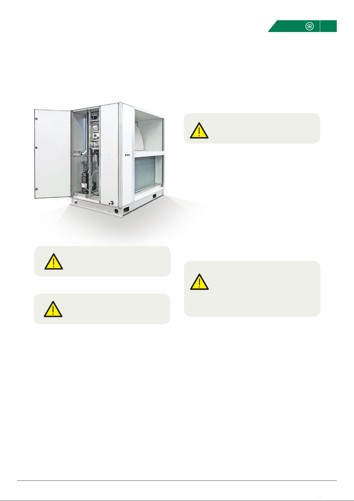
PRODUCT DESCRIPTION
The EQKR ReCooler is an integrated reversible heat pump
providing both heating and cooling. It consists of a rotary heat
exchanger and a Heat-pump unit. The ReCooler Heat-pump
has an independent control unit with heating-, cooling- and
thermal wheel demand supplied via an external control
source.
REFRIGERATION SYSTEM
The Reversible Heat-pump unit in the ReCooler is designed for
external air temperatures:
• Cooling+20to+40°C
• Heating,withelectricalheater+20to-20°C
• Heatingwithoutelectricalheater+20to-15°C
ROTOR UNIT
The rotor unit in the ReCooler is designed for heating and cool-
ing air by utilising the temperature differences in the outdoor
air and extract air. The rotor operates to recover energy from
the extract air in combination with the heat pump unit.
OPTIONAL ELECTRIC DEFROSTING COIL
The defrost electrical heater is mainly used to shorten defrost
cycle time. It’s also used as an additional heater when evapo-
rationtemperatureislow(<-21°C).Theelectricalheaterinclu-
des two thermal protectors:
• Anautoreset
• Amanualreset
1. Outdoor air
2. Supply air
3. Extract air
4. Exhaust air
5. Rotary heat exchanger - service hatch
6. Compressor
7. Frequency inverter for compressor
8. Drainage
9. Control system for the ReCooler
10. 4-way valve in wrong position
11. Main switch disconnector
12. Optional – Electrical heater
13. Cable glands
14. Electronic expansion valves
15. Handheld terminal for the ReCooler
3
5
13
11
14
14
10
12
15
1
2
4
6
7
9
8
8

Maintenance 5
Fläkt Woods 9568 GB 2015.08.11 Specifications are subject to change without further notice
EQKR ReCOOLER HP
DESCRIPTION OF THE FUNCTIONS
Size 008-032 1 circuit
Size 041-050 2 circuits
Size 072 3 circuits
Pos Total Component
1:1-3 1 Supply air coil
2:1-3 1 Exhaust air coil
3:1-3 1 4 way valve
4:1-3 1 Compressor
5:1-3 1 Liquid separator
6:1-3 1 Reciever
7:1-3 1 Filter dryer
9:1-3 1 EEV 2
10:1-3 1 EEV 1
11:1-3 1 High pressure sensor
12:1-3 1 Low pressure sensor
13:1-3 1 Suction gas sensor
14:1-3 1 Liquid temperature sensor
15:1-3 1 Discharge gas sensor
16:1-3 1 Low pressure service connector
17:1-3 1 High pressure service connector
18 1 Defrosting pressure sensor
19 1 Rotor
20 1 Electrical heater
GT6 1 Automatic thermal protection
GT7 1 Manual thermal protection
18
18
Room
Cooling mode
Heating mode
20
19
VVX
GT6 GT7
2:1-3
1:1-3
3:1-3
15:1-3
GT12:1-3
GT13:1-3
GT16:1-3
4:1-3
5:1-3 9:1-3
7:1-3
14:1-311:1-317:1-3
6:1-3
10:1-3
Room
Maintenance 6
Fläkt Woods 9568 GB 2015.08.11 Specifications are subject to change without further notice
EQKR ReCOOLER HP
SAFETY INSTRUCTIONS
LIFTING
Because of its design, the centre of gravity is offset towards
the inspection side. This must be taken into account when
lifting the unit. The unit should first be lifted slightly, and then
inspected to ascertain that it does not tilt or appear unstable
before being lifted higher.
DUTY OF NOTIFICATION AND IN-SERVICE
INSPECTION
Duty of notification
If the amount of refrigerant in a unit exceeds 10 kg the
supervisory authorities, generally the environmental health
department, must be informed. This information must be
provided well in advance of installation. More information
about this is contained in local refrigerant legislation.
Leak tracing during installation and in-service inspection
A leakage inspection must be carried out yearly on EQKR
008-072. This conforms to the EU regulation on fluorinated
greenhouse gases 517/2014.
Important!
The unit must be commissioned by
authorised personnel.
Important!
The unit’s centre of gravity is not in
the middle of the unit.
OPERATING AND CARE
MAIN COMPONENTS
A control panel is installed in the service section of the cooling
unit and includes the following components:
– Main electrical panel disconnect switch
– Miniature circuit breaker
– Control unit with display
COMPONENT DESCRIPTION
Control unit (KR1).
Microprocessor-based, programmable electronic controller.
MINIATURE CIRCUIT BREAKER
Automatically operated electrical switch designed to protect
an electrical circuit from damage caused overload or short
circuit.
MAIN ELECTRICAL PANEL DISCONNECT SWITCH
The disconnect switch is used to turn on/off power to the Re-
Cooler heat pump unit.
Always lock and tag the unit prior to performing any mainte-
nance or servicing work.
ELECTRICAL CONNECTIONS
Check the electrical schematics for additonal information with
regards to external connections (page 10).
Important!
Always read the safety directions on page 2
prior to beginning any work!
Warning!
The circuit breaker does NOT isolate
the power supply to the entire cooling unit!
Therefore always open and lock the main
switch before you begin any work on
the cooling unit.

Maintenance 7
Fläkt Woods 9568 GB 2015.08.11 Specifications are subject to change without further notice
EQKR ReCOOLER HP
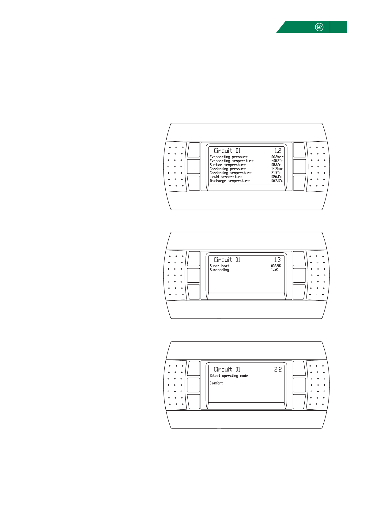
PGD1 HUMAN MACHINE INTERFACE
The ENTER button is used to scroll through the list of
available languages and the ESC button is used to
confirm the users selection.
The home screen shows the following information:
– Circuit that the display is connected to
– Operating mode (Cooling/Heating)
Status:
– Standby
– Start phase
– Unit running
– Start delay
– Defrost
– Alarm
& etc.
The current example shows:
– Compressor speed demand sent from external
control system: 75 %
– Current rotation speed of the compressor: 35 %
– Current speed of Rotary Heat Exchanger: 100 %
This screen displays information related to the current
status (operation mode) of the coils (condensing/eva-
porating) and whether the AHU is configured with
supply air in the upper or lower level.
Maintenance 8
Fläkt Woods 9568 GB 2015.08.11 Specifications are subject to change without further notice
PGD1 HUMAN MACHINE INTERFACE
EQKR ReCOOLER HP
Temperature and pressure values.
Superheat and sub-cooling.
This function is activated ONLY when the heat pump is
controlled via Analog control.
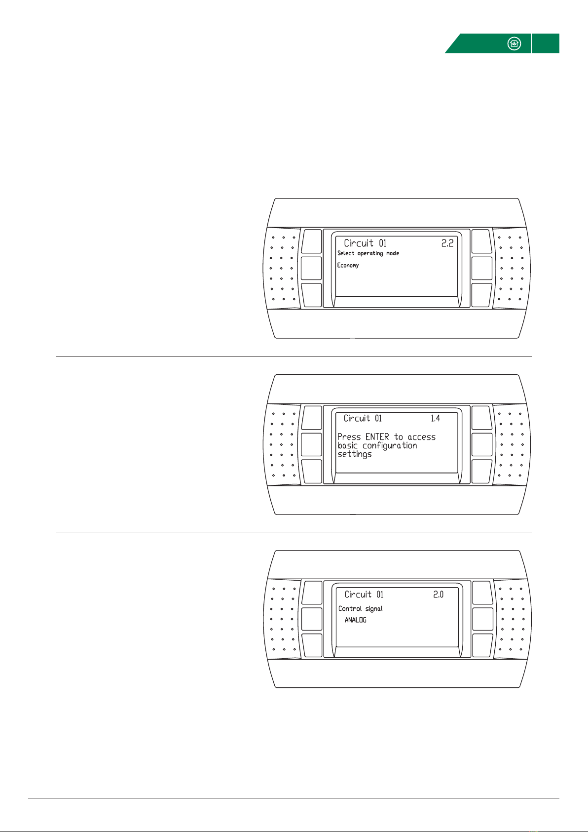
Default setting of the ReCooler HP unit.
1. At start-up, the rotating heat exchanger speed will
decelerate when the demand compressor speed is
less than the actual compressor speed.
2. With low demand and the compressor at its lowest
speed, the rotating heat exchanger will decelerate.
Maintenance 9
Fläkt Woods 9568 GB 2015.08.11 Specifications are subject to change without further notice
PGD1 HUMAN MACHINE INTERFACE
EQKR ReCOOLER HP
When the unit is running in economy mode, the rotating
heat exchanger is always first in the heating sequence and
only begins to decelerate when the compressor is off.
Access to additional basic configuration settings.
Used to select the heat pump control method
(Analog/Modbus),

Maintenance 10
Fläkt Woods 9568 GB 2015.08.11 Specifications are subject to change without further notice
EQKR ReCOOLER HP
PGD1 HUMAN MACHINE INTERFACE
Activating quick start will bypass the normal
compressor start up sequence.
Software information of the system.

Maintenance 11
Fläkt Woods 9568 GB 2015.08.11 Specifications are subject to change without further notice
EQKR ReCOOLER HP
MAINTENANCE
INSPECTION/MAINTENANCE
Regular inspection and maintenace in accordance with legi-
slation in force must be carried out by a certified refrigeration
technician.
INSPECTION
To be carried out by the owner/user once a week.
Check the following:
1. Indicated alarms
2. Abnormal noise/vibrations
3. Leakage
4. Corrosion, wear and tear
5. The interior of the unit, light fittings
MAINTENANCE
To be carried out by a certified refrigeration technician at least
once each year.
Check the following:
1. Evaporation/condensation temperature
2. Discharge temperature
3. Expansion valves
4. Safety equipment
5. Cooling and heating capacity
6. Unit system test
7. Electrical equipment
8. Coils, drip tray and the drainage system
9. Air filter
Important!
Always read the safety directions on page 2
prior to beginning any work!
RECURRING CHECKS
Must only be carried out by a certified refrigeration technician.
Inspect the system at least once every 12 months and maintain
a journal.
Check the following wherever applicable:
1. Piping
2. Inspection to detect refrigerant leakage
3. Check for abnormal vibrations
4. Check to detect possible corrosion
5. Whether filling with additional refrigerant is needed
6. Check to detect possible oil leakage
7. Safety equipment
8. Connection joints/Seals
DISMANTLING
When dismantling (scrapping) this type of unit, the refrigerant
and compressor oil must unconditionally be collected and
contained for destruction/recycling.
SPARE PARTS
Spare parts can be bought via local cooling suppliers. Contact
your local Fläkt Woods office for information regarding com-
ponents that need to be replaced.
Table of contents


