flakt woods FC102 User manual

AIR COMFORT
Content Page
Safety instructions 2
IT system 3x230VAC 2
Connections 3
Control unit (LCP) 4
Manual operation 4
Reverse the direction of rotation 4
More information 4
Wiring diagram 5
Basic configuration 6
PID regulation 7
AIR TREATMENT
9325 GB 2016.09.16
AIR COMFORT
» INSTALLATION AND MAINTENANCE
FREQUENCY CONVERTER
FC102 (QUICK GUIDE)

Installation and maintenance 2
Fläkt Woods 9325 GB 2016.09.16 Specifications are subject to change without further notice
FREQUENCY CONVERTER FC102 (QUICK GUIDE)
SAFETY INSTRUCTIONS
• Check that the frequency converter is correctly connected
to earth.
• Do not pull out the mains or motor contacts or other power
connections when the frequency converter is connected to
the power supply grid.
• Protect the user from mains voltage.
• Protect the motor against overload in accordance with
national and local regulations.
• The leakage currents to earth exceed 3.5 mA, see Design guide.
• The [Off] button is not an isolator switch. It does not discon-
nect the frequency converter from the mains.
WARNING!
Warning high voltage
The frequency converter is subject to highly
dangerous voltages when it is connected to
the mains. Incorrect installation of the motor
or frequency converter can lead to material
damage, serious personal injury or death.
Follow the instructions in this manual as well
as local and national provisions and safety
regulations.
WARNING!
Discharge time!
Frequency converters have DC bus capacitors
that can hold a charge even after the mains vol-
tage has been disconnected. Prevent electrical
hazards by disconnecting the mains voltage,
disconnecting permanent magnet motors and
DC bus supplies, including battery backup, UPS
and DC bus connections for other frequency
converters. Wait until the capacitors have fully
discharged before carrying out maintenance or
repairs. Read more about the discharge waiting
times in the table below. Starting to service or
repair the unit immediately after cutting the
power supply, without waiting for the specified
period, can lead to death or serious personal
injury.
TAKE CARE!
Residual current device:
This product can cause a direct current in
the protective earth conductor. When using a
residual current device as additional protec-
tion, use only a type B residual current device
(delayed) on the input side of this product. See
also Danfoss application note for the MN90G
RCD.
The protective earthing of the frequency
converter and the use of RCDs must always
follow national and local regulations.
TAKE CARE!
IT system (3x230VAC)
When installing the FC102 on an isolated
system (IT system, 3x230VAC) set parameter
14-50 to [0] Off.
Press [Main Menu] twice. Navigate using
the [▲] [▼] and [OK] buttons until parameter
14–50 is displayed (select 14–**, then 14–5*
and lastly 14–50). Set this parameter to [0] Off.
WARNING!
Installation at heights
For installation at height, contact Fläkt Woods
regarding PELV.
Voltage
(V)
Output range
(kW)
Minimum waiting
time (min)
200 – 240 1.1 – 3.7 4
200 – 240 5.5 – 45 15
380 – 480 1.1 – 7.5 4
380 – 480 11 – 90 15
Installation and maintenance
3
Fläkt Woods 9325 GB 2016.09.16 Specifications are subject to change without further notice
FREQUENCY CONVERTER FC102 (QUICK GUIDE)
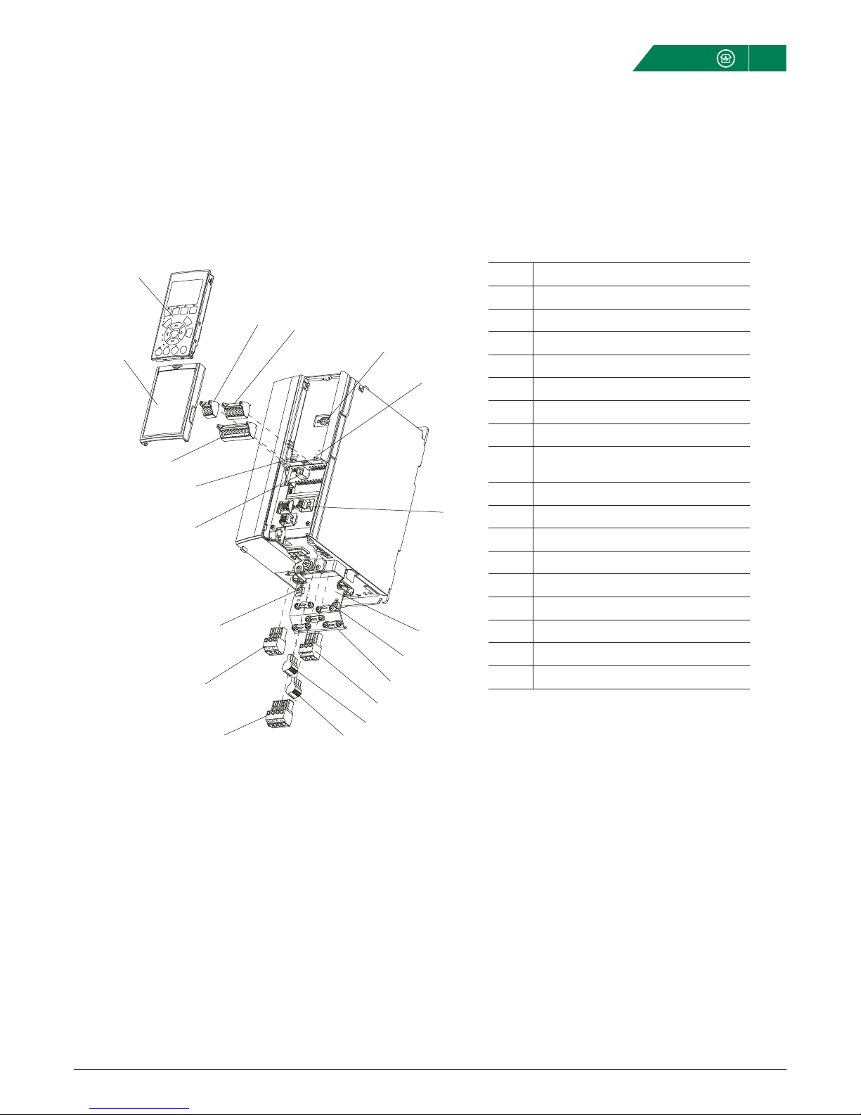
CONNECTIONS – PRINCIPLE IMAGE
1 Control unit (LCP)
2 RS 485 serial bus
3 Analogue I/O
4 LCP contact
5 Analogue switches
6 Cable support/ PE earth
7 Earthing plate
8 Earth clamp
9 Shielded cable earth clamp and cable
support
10 Motor connection
11 Relay 1
12 Relay 2
13 Brake and load distribution terminal
14 Mains connection
15 USB
16 Serial bus, terminal switch
17 Digital I/O and 24 V
18 Cover panel
1
23
4
5
6
7
8
9
10
11
12
13
14
8
15
16
17
18
130BB492.10
1
2
17
16
15
14
13
10
11
12
8
3
4
5
6
7
8
9
18
Installation and maintenance
4
Fläkt Woods 9325 GB 2016.09.16 Specifications are subject to change without further notice
FREQUENCY CONVERTER FC102 (QUICK GUIDE)
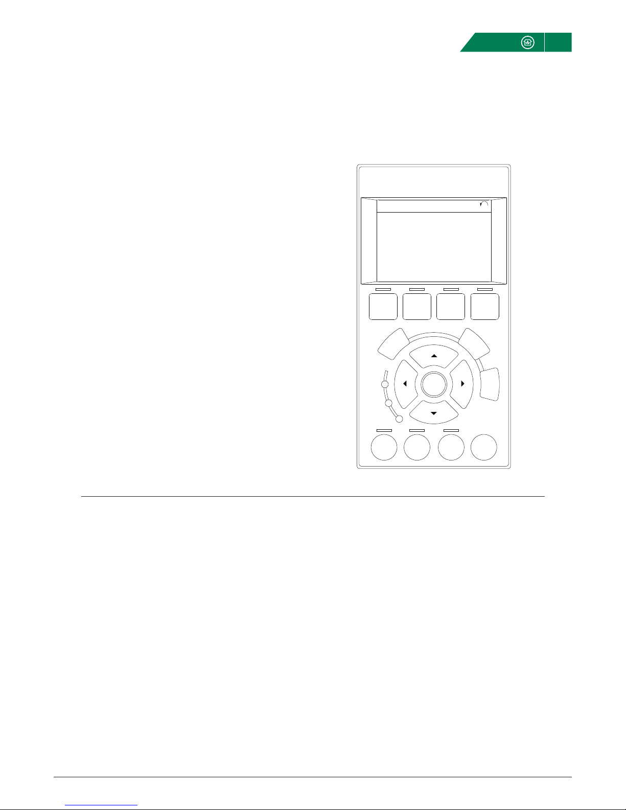
CONTROL UNIT (LCP)
A. Alphanumeric display
The information displayed in the control unit display (LCP) can
be customised. See parameters 0–20, 0–21, 0–22, 0–23 and
0–24. The factory settings display: motor rpm, motor current,
motor output, motor frequency and reference.
B. Menu buttons
Use the menu buttons to access the parameter settings, to
toggle between status display modes during normal operation
and to display fault log data.
C. Navigation and indication
[Back] returns to the previous step or menu list [Cancel]
Cancel the latest change or command [Info] Provides informa-
tion of the function displayed [▲] [▼] [▲] [▼] navigate and
increase/decrease [OK] Activate selection or access a
parameter group
• Green indication – power on
• Yellow indication – warning
• Red indication – alarm
D. Driftslägesknappar och återställning
[Hand/on] – Starting the motor for local control
[Off] – Stopping the motor
[Auto/on] – Allow control via control terminals or the commu-
nication bus
[Reset] – Resetting alarms
MANUAL OPERATION
• Press [Hand/on] to start
• Press the navigation buttons to set the desired speed
• Press [Off] to stop
• Press [Auto/on] to return to automatic operation
REVERSE THE DIRECTION OF ROTATION
If necessary the direction of rotation can be reversed using
parameter 1–06. When connection is correct 0=clockwise and
1=anti-clockwise.
MORE INFORMATION
This quick guide contains the basic information needed to
install and operate the frequency converter.
There is more information available in the attached docu-
mentation.
Auto
on Reset
Hand
on O
Status Quick
Menu
Main
Menu
Alarm
Log
Cancel
Info
Status 1(1)
1234rpm
Back
OK
43,5Hz
Run OK
43,5Hz
On
Alarm
Warn.
130BC362.10
a
b
c
d
1.0 A
a
b
c
d
Installation and maintenance
5
Fläkt Woods 9325 GB 2016.09.16 Specifications are subject to change without further notice
FREQUENCY CONVERTER FC102 (QUICK GUIDE)
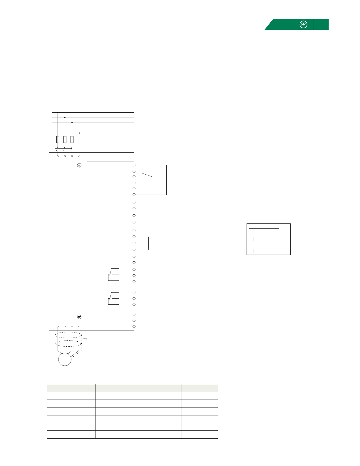
WIRING DIAGRAM
SIGNALS
Designation Type Terminal block
Start Potential-free closure 12-18
Control signal 0...10VDC 53
Pressure/ow sensor 0...10VDC (4...20mA) 54
COM For analogue in (Terminal blocks 53, 54) 55
Alarm R1 NO/NC 01, 02, 03
Operation R2 NO/NC 04, 05, 06
Relay output 0
Alarm NO/NC (Param. 5-40.0)
Relay output 1
Run Indicator NO/NC (Param. 5-40.1)
Start
Reference 0…10VDC (FW standard)
Actual value PID regulation
Start
+
-
+
-
Danfoss FC102
+24V 12
+24V 13
DIG IN 18
DIG IN 19
COM 20
DIG IN 27
DIG IN 29
DIG IN 32
DIG IN 33
DIG IN 37
+10V 50
A IN 53
A IN 54
COM 55
A OUT 42
COM 39
01
02
03
04
05
06
RS-485 com 61
RS-485 + 68
RS-485 - 69
R2 R1
91 92 93 95
L1 L2 L3 PE
U V W PE
96 97 98 99
L1
F1
L2
L3
N
PE
Analog switches
ON = 0-20m
OFF = 0-10VDC
A54
A53
ON
12
ON
12
M
The basic configuration (Fläkt Woods standard) relates to 0...10 VDC control via terminal block 53.
To activate the internal PID regulator see page 6. The sensor is connected to terminal block 54.

Installation and maintenance 6
Fläkt Woods 9325 GB 2016.09.16 Specifications are subject to change without further notice
FREQUENCY CONVERTER FC102 (QUICK GUIDE)
BASIC CONFIGURATION FOR ASYNCHRONOUS MACHINES (FLÄKT WOODS STANDARD)
When the frequency converter is energized for the first time the language can be selected. Obviously this can be changed later.
After Smart Start is started for 0...10VDC control by pressing [▼], followed by pressing [OK].
See motor
plate
See motor
plate
≥30s
≥40s
Step Description TF FF
1 Language English English
2 Select Q3 Function Setups Asynchronous Asynchronous
3 Number of motors 1 1
4 Thermal motor protection ETR 1 ETR 1
5 Motor Power [kW] _________________ _________________
6 Motor Voltage _________________ _________________
7 Motor Current _________________ _________________
8 Motor Frequency _________________ _________________
9 Motor Nominal Speed _____ _____
10 Minimum Reference 0 Hz 0 Hz
11 Maximum Reference ______________Hz ______________Hz
12 Apply on terminal block 53 Yes Yes
13 Application Fan Fan
14 Autom Energy Optimisation ❏ Yes (2, 4-pon) ❏ Yes (2, 4-pin)
❏ No (other) ❏ No (other)
15 AMA Yes Yes
16 Confi rm AMA OK OK
17 Press [Main Menu] twice
18 Select 3-** Reference / Ramps
19 Select 3-4* Ramp 1
20 [3-41] Ramp 1, Ramp Up Time _________________ _________________
21 [3-42] Ramp 1, Ramp Down Time _________________ _________________
When the frequency converter is energized for the first time the language can be selected. Obviously this can be changed later.
After Smart Start is started for 0...10VDC control by pressing [▼], followed by pressing [OK].
Confi guration carried out by __________________________________________________ Date ________________________________
Smart Start can be reactivated at any time. First press [Quick Menus]. Then navigate using the [▲] and [▼] buttons until the
cursor is on Q4 Smart Start. Then press [OK].
Danfoss factory reset
Press [Main Menu] twice. Navigate using the [▲] [▼] and [OK] buttons until parameter 14–22 is displayed (select 14–**,
then 14–2* and lastly 14–22). Set this parameter to [2] and then switch off the mains voltage.
When the frequency converter is re-energised the parameters will have returned to their factory settings.

Installation and maintenance 7
Fläkt Woods 9325 GB 2016.09.16 Specifications are subject to change without further notice
FREQUENCY CONVERTER FC102 (QUICK GUIDE)
ACTIVATING PID REGULATION
See sensor
See sensor
Setpoint
Adjust if
necessary
Step Description TF FF
1 Press [Quick menus]
2 Press [Quick menus]
3 Select Q3-3 Closed Loop Settings
4 Select Q3-30 Single Zone Int.Setpoint
5 1-00 Confi guration Mode [3] Closed Loop [3] Closed Loop
6 20-12 Reference/Feedback Unit [72] Pa [72] Pa
7 20-13 Minimum Reference/Feedb. 0 Pa 0 Pa
8 20-14 Maximum Reference/Feedb. ______________Pa ______________Pa
9 Press [▼] once
10 6-24 Terminal 54 Low Ref./Feedb. 0 Pa 0 Pa
11 6-25 Terminal 54 High Ref./Feedb. ______________Pa ______________Pa
13 6-26 Terminal 54 Filter Time Const ≥1 s ≥1 s
14 Press [▼] four times
15 20-21 Setpoint 1 ______________Pa ______________Pa
16 20-81 PID Normal/Inverse Control [0] Normal [0] Normal
17 Press [▼] twice
18 20-93 PID Start Speed 2.0 2.0
19 20-94 PID Proportional Gain 30.0s 30.0s
20 Press [Main Menu] twice
21 Select 0–** Operation / Display
22 Select 0–2* LCP Display
23 0–20 Display Line 1.1 Small [1654] Feedback 1 [1654] Feedback 1
Confi guration carried out by __________________________________________________ Date ________________________________

Installation and maintenance
8
Fläkt Woods 9325 GB 2016.09.16 Specifications are subject to change without further notice
FREQUENCY CONVERTER FC102 (QUICK GUIDE)
MODBUS RTU IN EQ
If Modbus RTU is used in eQ AHU for controlling drives, they
must be set according to the table below.
Configuration
Parameter Description Value
8-30 Protocol [2] Modbus RTU
8-31 Address Supply fan: 60
Exhaust fan: 70
8-32 Baudrate [2] 9600
8-33 Parity / Stop bits [2] No parity, 1 Stop bit
Parameter Description TF FF
6-50 Function, terminal block 42 4-20mA 4-20mA
Parameter Description TF FF
6-14 Output frequency
equivalent to 4mA 0 Hz 0 Hz
6-15 Output frequency
equivalent to 20mA ____Hz ____Hz
PARALLEL OPERATION
When two frequency converters are to operate in parallel, one
must be configured as master and the other as slave.
After this, connect the two frequency converters together as
indicated below.
Configuration, master
Configuration, slave
Set switch A53 (located under the display) to position I.
The power to the converter must be switched off.
Connection
Master Slave
42
39
53
55
Table of contents
Popular Media Converter manuals by other brands


SIIG
SIIG RS-232 to Multi-Mode Fiber Optic Quick installation guide

Omnitron Systems
Omnitron Systems OmniConverter FPoE/SL user manual

Repotec
Repotec RP-IMC811FP user manual

CYP
CYP SY-300H-4K22 operating manual

Schumacher Electric
Schumacher Electric PC-6 owner's manual

Chiayo
Chiayo GMC-60 Operation manual