Mantracourt DSC User manual
DSC/DLC User Manual
mantracourt.com
DSC/DLC

Mantracourt Electronics Limited DSC/DLC User Manual
1
Introduction ..........................................................................................................................................................3
Navigating This Manual ...........................................................................................................................................................................3
General features ..........................................................................................................................................................................................3
Product codes explained..........................................................................................................................................................................3
Which version do I need? ........................................................................................................................................................................3
Installation ............................................................................................................................................................5
Mounting .......................................................................................................................................................................................................5
General .......................................................................................................................................................................................................5
DLC...............................................................................................................................................................................................................5
DSC ..............................................................................................................................................................................................................5
Wiring ..............................................................................................................................................................................................................6
General .......................................................................................................................................................................................................6
DLC Wiring................................................................................................................................................................................................7
DSC Wiring............................................................................................................................................................................................. 11
DSC Toolkit ........................................................................................................................................................ 18
Overview...................................................................................................................................................................................................... 18
What can the Toolkit do?................................................................................................................................................................. 18
Installing the DSC Toolkit ..................................................................................................................................................................... 18
Toolkit Details............................................................................................................................................................................................ 19
Home........................................................................................................................................................................................................ 19
Information............................................................................................................................................................................................ 25
Communication.................................................................................................................................................................................... 26
Save and Restore................................................................................................................................................................................. 39
Logging ................................................................................................................................................................................................... 40
Data rate and Filters........................................................................................................................................................................... 42
User Area ................................................................................................................................................................................................ 43
End User Calibration .......................................................................................................................................................................... 44
OEM Advanced Calibration ............................................................................................................................................................. 52
Advanced Usage ................................................................................................................................................ 65
The Measurement/Readings Process............................................................................................................................................... 65
Electrical.................................................................................................................................................................................................. 65
Cell ............................................................................................................................................................................................................ 65
System ..................................................................................................................................................................................................... 65
Changing Sensitivity ............................................................................................................................................................................... 66
DLC............................................................................................................................................................................................................ 66
DSC ........................................................................................................................................................................................................... 67
Specifications..................................................................................................................................................... 68
DLC and DSC.............................................................................................................................................................................................. 68
Technical Specifications.................................................................................................................................................................... 68
Appendices......................................................................................................................................................... 70
Appendix A - Communication Interface ......................................................................................................................................... 70
RS232 ....................................................................................................................................................................................................... 70
RS485 ....................................................................................................................................................................................................... 70
CAN........................................................................................................................................................................................................... 70
Appendix B - Communication Protocol .......................................................................................................................................... 71
ASCII ......................................................................................................................................................................................................... 71
Mantrabus II .......................................................................................................................................................................................... 74
Modbus RTU ......................................................................................................................................................................................... 76
MantraCAN............................................................................................................................................................................................ 79
CANopen® ............................................................................................................................................................................................ 83
Appendix C - Commands ..................................................................................................................................................................... 89
Command list ASCII, Mantrabus, Modbus ................................................................................................................................ 89
Parameter Detail General................................................................................................................................................................. 90
Command List MantraCAN ............................................................................................................................................................. 95
Parameter List CANopen................................................................................................................................................................103

Mantracourt Electronics Limited DSC/DLC User Manual
2
Appendix D - Product code list........................................................................................................................................................104
DLC..........................................................................................................................................................................................................104
DLC..........................................................................................................................................................................................................104
Appendix E - Accessories....................................................................................................................................................................105
DTEMP ...................................................................................................................................................................................................105
DSJ1 ........................................................................................................................................................................................................106
DSJ4 ........................................................................................................................................................................................................108
Appendix F - Digital Filtration...........................................................................................................................................................110
Appendix G - Toolkit Supported CAN Controllers ...................................................................................................................111
Appendix H - Trouble Shooting.......................................................................................................................................................112
Status LED ............................................................................................................................................................................................112
Diagnostic Flags.................................................................................................................................................................................112
No Communications ........................................................................................................................................................................112
Bad Readings ......................................................................................................................................................................................113
Unexpected Warning Flags ...........................................................................................................................................................114
Problems with Bus Baud Rate ......................................................................................................................................................114
Port problems.....................................................................................................................................................................................114
Recovering a lost DSC/DLC ...........................................................................................................................................................115
Appendix I - Known Issues.................................................................................................................................................................116
Finite Non-Volatile Memory Life.................................................................................................................................................116
CANopen ..............................................................................................................................................................................................116
Appendix J - Declaration of Conformity .......................................................................................................................................117
Appendix K - Warranty ........................................................................................................................................................................118
Mantracourt Electronics Limited DSC/DLC User Manual
3
Introduction
Navigating This Manual
When viewing this PDF manual the following tips will help you navigate.
Viewing bookmarks ( or ) to the side of the page, in the PDF viewer, will allow easy navigation to the relevant
chapters of this manual. Alt-left arrow is a useful shortcut back to the last page viewed after a hyperlink is clicked.
Hyperlinks are coloured purple and are underlined.
General features
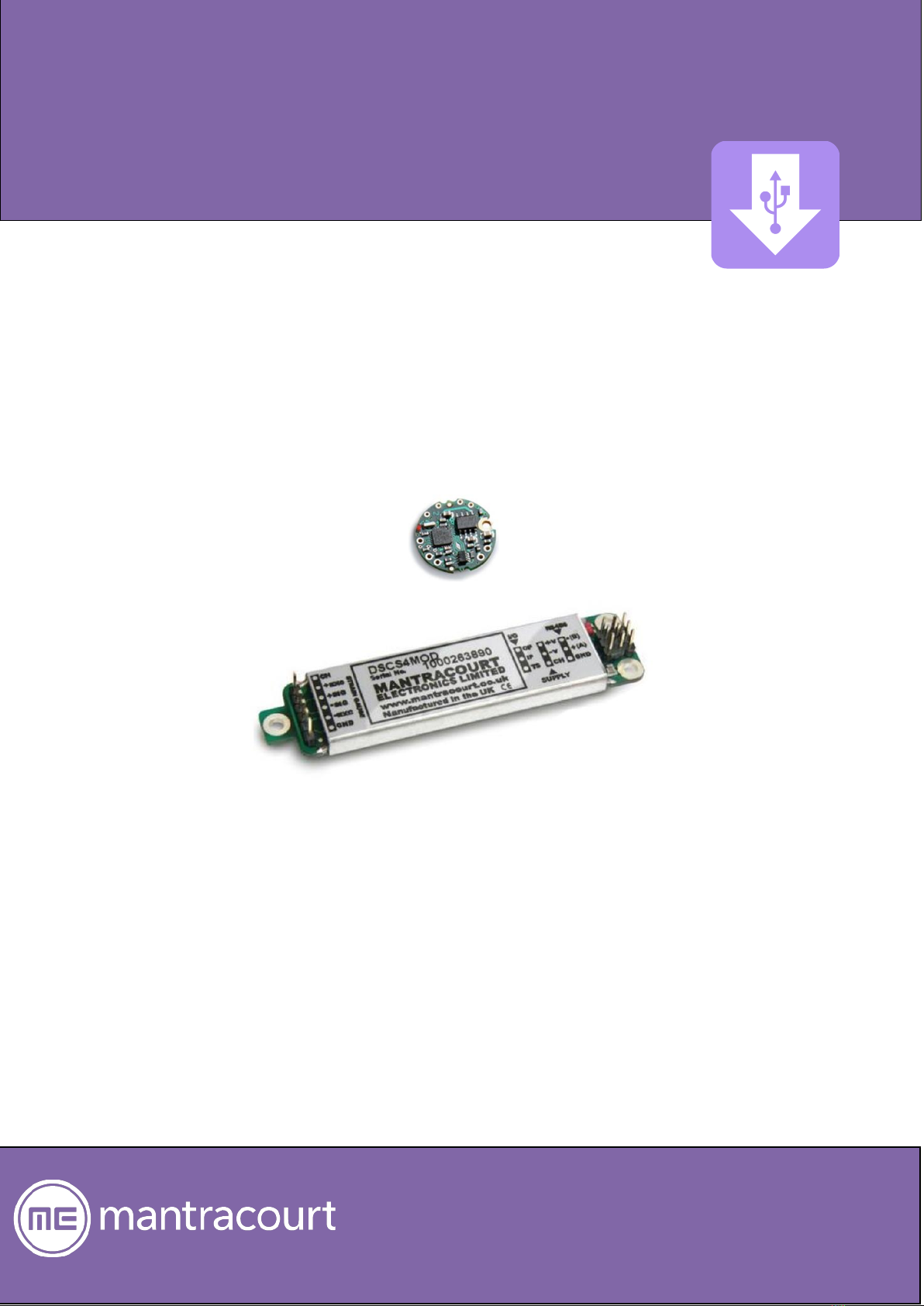
Mantracourt’s DSC/DLC is a range of products for digitizing a strain-based bridge input such as a load cell. The
DSC is a card type with pins for easy installation while the DLC is a disc designed to be fitted inside the pocket of
a load cell or other sensor.
Accessories available include an external temperature sensor (DTEMP), one- and four-way mounting boards with
two-part connectors (DSJ1 and DSJ4) and a display unit for use with the Mantrabus versions (DS485DIS). These
are detailed later.
Setup and configuration is made easier with the free Toolkit software but can be achieved via comms if necessary.
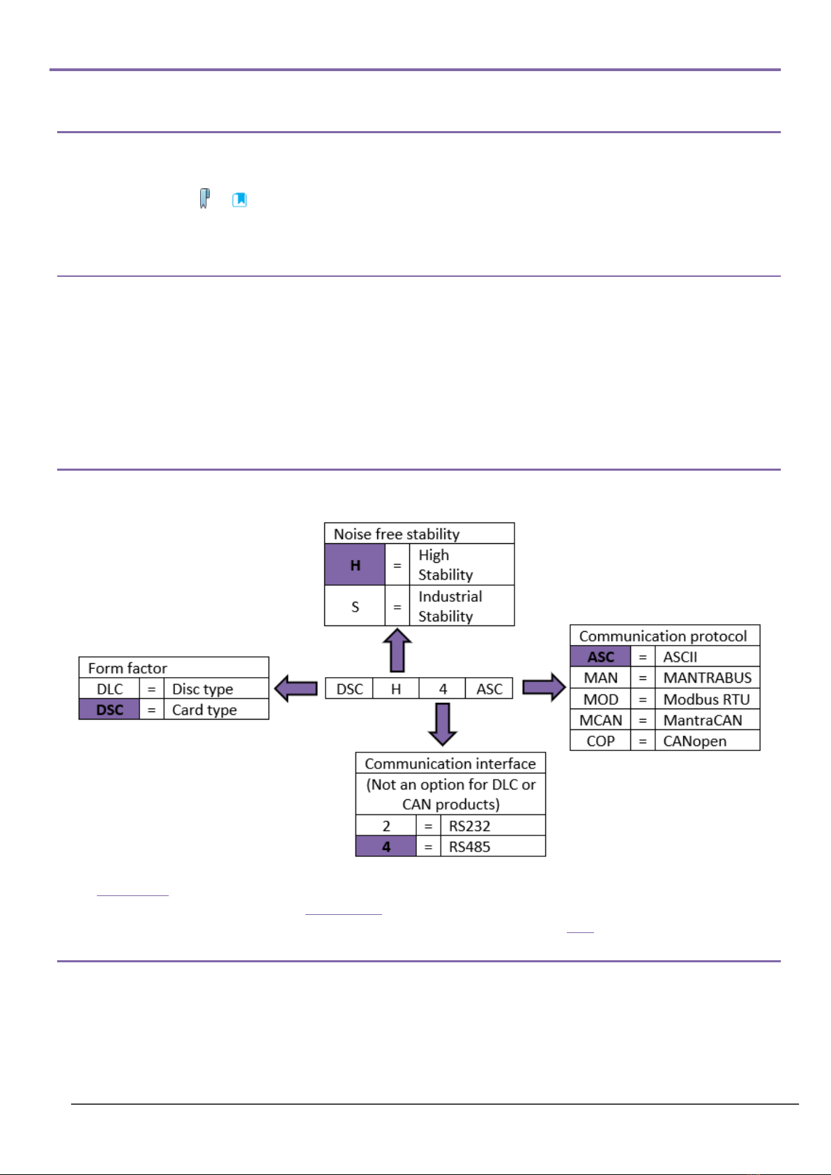
Product codes explained
See Appendix D for full list of available types.
Different stabilities are detailed in the specification.
The implementation of the communication interfaces and protocols are detailed here.
Which version do I need?
The choice of hardware interface, RS232, RS485 or CAN, is dependent on the interface available at the other end, whether it’s a
single or multiple units required as RS232 is only suitable for one-to-one connections and RS485 and CAN are suitable for
single and multi-drop applications. Another factor is length of cables required as RS232 is typically used for cable lengths of
approx. 25m. RS485 has a differential topology and is better for noise immunity.

Mantracourt Electronics Limited DSC/DLC User Manual
4
The choice of protocol is normally based on what master/controller is to be used which may also depend on other third party
devices on the bus. Modbus is a standard protocol so multi vendor devices can all work happily using this standard protocol.
Mantrabus is a hex based protocol which has fewer packet overheads. It is a proprietary protocol so only Mantracourt
products can operate on the bus. ASCII may be chosen as it may seem easier to write software for and debug. When ASCII is
used in a streaming mode then this can feed directly into an ASCII display terminal or viewed directly on a PC using a
terminal/teletype software tool.
Again, CAN based systems will depend on what you already have. CANopen is a well established protocol administered by the
CiA. MantraCAN is a proprietary CAN protocol that can be made to mimic other protocols such as J1939 by setting up custom
messages. If you are creating your own stand alone system MantraCAN may be easier to implement than CANopen.

Mantracourt Electronics Limited DSC/DLC User Manual
5
Installation
Mounting
General
It is advisable to follow the below installation practice where possible
•Minimise vibration
•Do not mount next to strong electrical or magnetic fields (transformers, power cables)
•Always ensure the device is secure and protected from damage
DLC
The DLC is designed to be sealed in the pocket of the sensor, which provides electrical shielding for EMC and
noise as well as mechanical and moisture protection. If mounting outside the sensor, then it is unlikely to achieve
specified performance.
The DLC must be mounted using a 2 mm screw to the body of the sensor. This should be a good electrical
connection to obtain optimal performance.
The 2 mm mounting hole accepts M2 screw or American equivalent #0-80.
Important Note: DO NOT USE #2 screw size.
Additional moisture protection can be obtained using a potting compound such as a two-part epoxy. Care must
be taken to avoid any gaps as the resulting mechanical stresses could damage the device. The compound chosen
must be specified for electrical use and have enough thermal conductivity for the heat generated by the device.
(Up to 1 W with a 15 V supply).
DSC
The DSC is normally installed in a protective enclosure, such as a metal box.
The pins can be plugged into standard (2.54 mm pitch) PCB header sockets or soldered directly into a host board
or to connecting wires.
It can be mounted either way up. Unwanted pins projecting on one side may be cropped off (carefully!)
For extra vibration resistance and grounding, the 3 mounting holes provided can be used.
If necessary, the protruding end with single hole can be cut off to make board smaller. However this needs to be
done with great care so that damage does not occur.

Mantracourt Electronics Limited DSC/DLC User Manual
6
Wiring
General
All the sensor wires should be kept as short as feasible.
The EXC+/–wires should be a twisted pair, also the SIG+/–pair, and the two pairs kept apart. It is also
recommended to secure the wires from moving due to shock or vibration.
The cable must enter the load cell via an EMC cable gland, which connects the cable shield to the load cell body.
This must be a 360-degree connection.
To obtain the best EMC results, wire as shown in wiring examples below. However, this has the potential to create
earth loops.
Devices are protected against shorting of communications lines to power supply and shorting of sensor inputs.
There is no over current protection in case of faults so power limiting or fusing should be provided.
Power and communication should use twin (or triple for RS232) twisted pair cable with independent shields.
Characteristic impedance should be 50-150 ohms and core to core/shield to core capacitance should be below
300 pF/m. (EG Belden type 8723 or 8777)
Soldering
Use a temperature controlled soldering iron set to a maximum of 330 °C, for no longer
than 2 seconds per pad. Excessive heat transferred to the PCB will result in damage.
Do not use solder with a water soluble flux. This can leave a surface film which attracts
moisture and degrades measurement performance.

Mantracourt Electronics Limited DSC/DLC User Manual
7
DLC Wiring
Connecting wires are soldered directly to the pads on the top and/or bottom of the PCB. Care must be taken to
electrically insulate the connection pads from the surrounding metal.
The wiring on the load cell side should ideally be kept to less than 20 cm.
RS485
For products DLCHASC, DLCHMAN, DLCHMOD, DLCSASC, DLCSMAN, DLCSMOD.
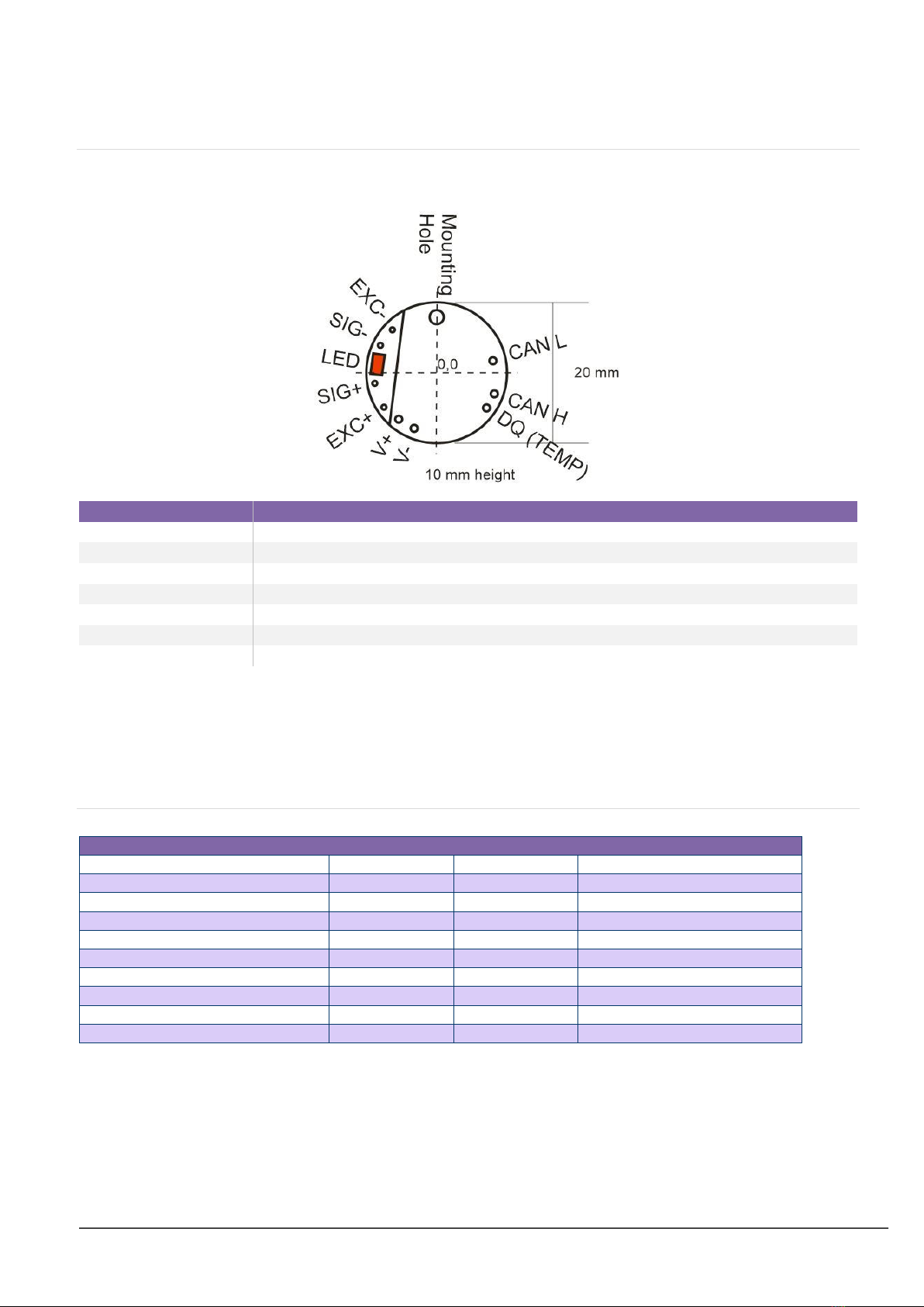
Pinout
Item
Description
Mounting hole
For mounting and grounding (see mounting above)
EXC+/-
Excitation for bridge sensor
SIG+/-
Signal from bridge sensor
V+/-
Power supply for DLC (5.6-18 VDC)
A+/B-
RS485 connections (note these can be referred to in several different ways, depending
on the manufacturer)
DQ (TEMP)
Connection for DTEMP device (EXC- of DTEMP should be connected to V-)
LED
Status LED. (see troubleshooting)
There MUST be a common connection from the PSU V- and the RS485 master’s ground to ensure the RS485
stays within the required common mode voltage of +/-7 V.
The shield should be connected to the grounded enclosure of the power supply.
120 ohm termination resistors should be used at either end of the bus to stop reflections.
Pad Positions
(mm from 0,0)
x
y
Hole diameter
Mounting hole
0.0
+7.9
2.0
-V
+6.2
+6.1
1.0
+V
+7.9
+3.8
1.0
RS485-(B)
+5.8
-6.6
1.0
RS485+ (A)
+3.6
-8.1
1.0
Temp sensor DQ
-1.3
-8.8
1.0
+EXC
-7.5
-4.9
0.7
+SIG
-8.8
-1.5
0.7
-SIG
-8.0
+3.9
0.7
-EXC
-6.3
+6.1
0.7

Mantracourt Electronics Limited DSC/DLC User Manual
8
Wiring Example
Mantracourt Electronics Limited DSC/DLC User Manual
9
CAN
For products DLCHCAN, DLCHCOP, DLCSCAN, DLCSCOP.
Pinout
(note: stacked PCB assembly)
Item
Description
Mounting hole
For mounting and grounding (see mounting above)
EXC+/-
Excitation for bridge sensor
SIG+/-
Signal from bridge sensor
V+/-
Power supply for DLC (5.6-18 VDC)
CAN L/H
CANbus connections
DQ (TEMP)
Connection for DTEMP device (EXC- of DTEMP should be connected to V-)
LED
Status LED. (see troubleshooting)
There MUST be a common connection from the PSU and the CAN ground to ensure the CAN stays within the
required common mode voltage of -2v (CANL) to +7v (CANH).
The shield should be connected to the grounded enclosure of the power supply.
120 ohm termination resistors should be used at either end of the bus to stop reflections.
For bus rates greater than 500 kbps cable such as Belden 8132 is recommended.
Pad Positions
(mm from 0,0)
x
y
Hole diameter
Mounting hole
0.0
8.1
2.0
-V
-3.2
-7.9
1.0
+V
-5.4
-6.6
1.0
CAN L
8.0
1.7
1.0
CAN H
8.2
-3.0
1.0
Temp sensor DQ
7.1
-5.0
1.0
+EXC
-7.5
-4.9
0.7
+SIG
-8.8
-1.5
0.7
-SIG
-8.0
3.9
0.7
-EXC
-6.3
6.1
0.7

Mantracourt Electronics Limited DSC/DLC User Manual
10
Wiring Example
Mantracourt Electronics Limited DSC/DLC User Manual
11
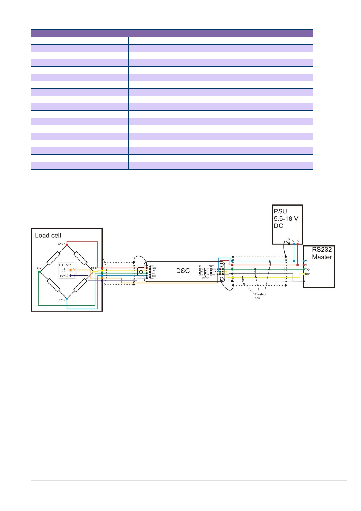
DSC Wiring
The pins can be plugged into standard (2.54 mm pitch) PCB header sockets or soldered directly into a host board
or to connecting wires.
RS232
For products DSCH2ASC, DSCH2MAN, DSCH2MOD, DSCS2ASC, DSCS2MAN, DSCS2MOD.
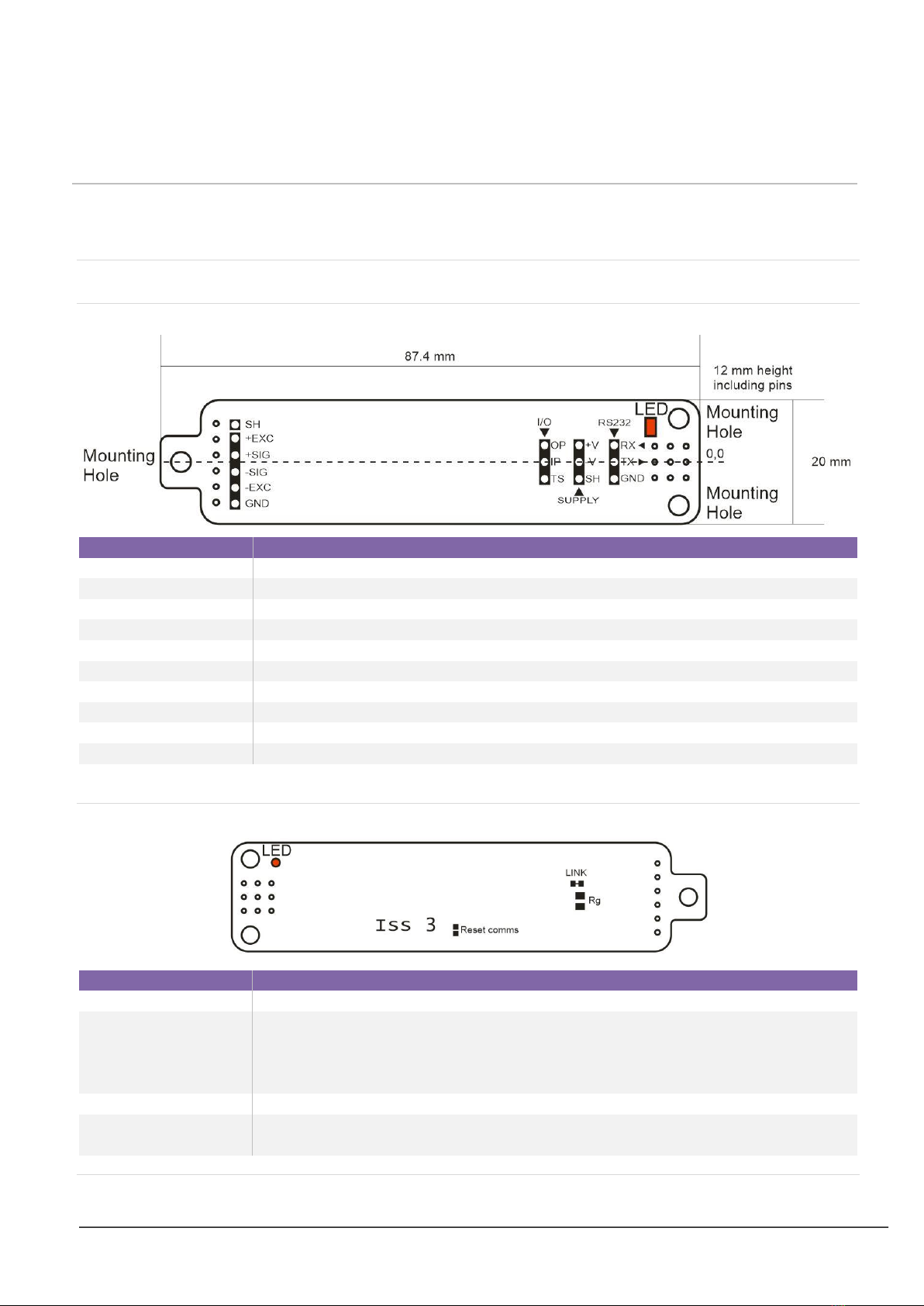
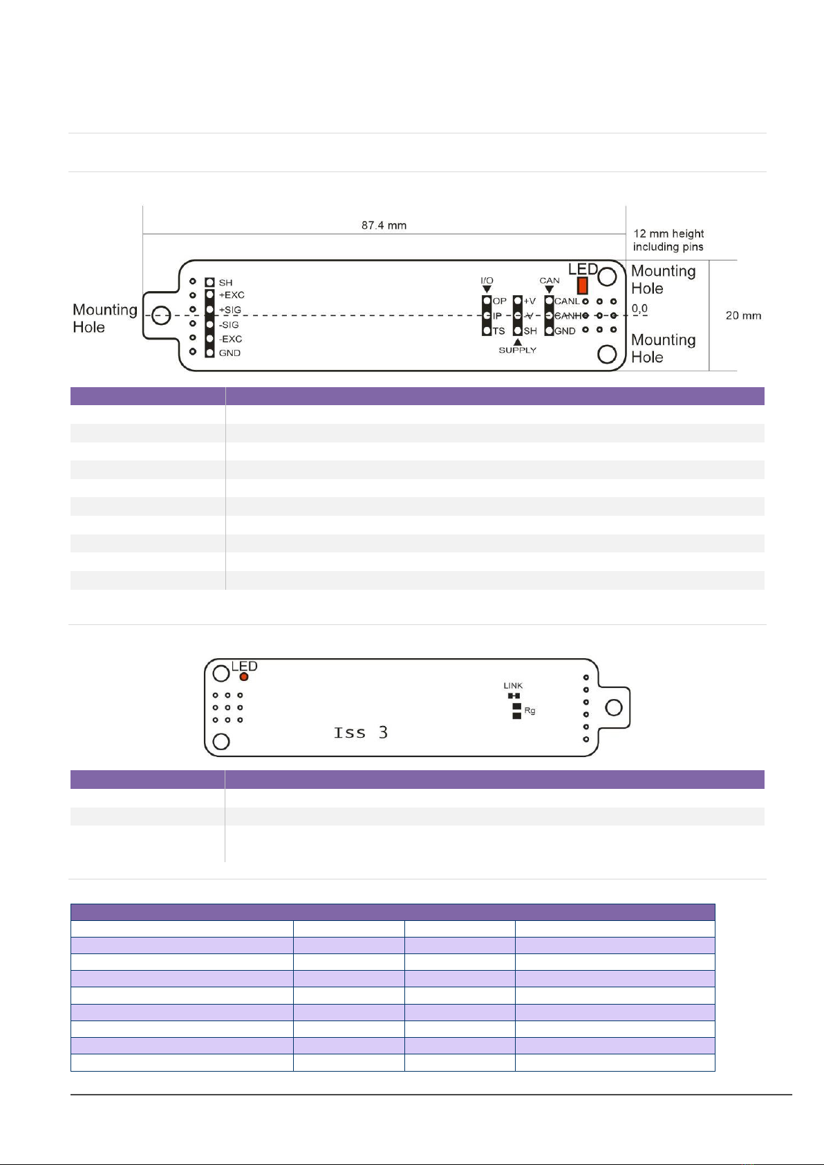
Pinout
Front
Item
Description
Mounting holes
For mounting and grounding (see mounting above)
SH (x2)
Shield connection for cable screen
EXC+/-
Excitation for bridge sensor
SIG+/-
Signal from bridge sensor
GND (x2)
Ground for DTEMP and RS232
IP/OP
Digital In/Out
TS
Connection for DTEMP device (EXC- of DTEMP should be connected to GND or V-)
V+/-
Power supply for DSC (5.6-18 VDC)
RX/TX
RS232 receive and transmit connections
LED
Status LED. (see troubleshooting)
Rear
Item
Description
LED
Status LED is visible through the board
Reset comms
RS232 and RS485 versions of the DSC have the ability to reset the communication
settings to defaults (station number 1 and baud rate 115200) by shorting the reset
comms pads together whilst powering up the DSC. You will then need to power cycle
the DSC for the changes to be applied.
LINK
If you are changing the gain of the device, this link may need to be cut if (see later)
Rg
If changing the gain of the device the new gain resistor should be mounted here (see
later)
Pin positions
Mantracourt Electronics Limited DSC/DLC User Manual
12
(mm from 0,0)
x
y
Hole diameter/pin size
Mounting hole 1
-84.1
0.0
3.2
Mounting hole 2
-7.3
7.0
3.2
Mounting hole 3
-7.3
-7.0
3.2
SH
-78.4
6.2
0.9
+EXC
-78.4
3.7
0.9
+SIG
-78.4
1.1
0.9
-SIG
-78.4
-1.4
0.9
-EXC
-78.4
-4.0
0.9
GND
-78.4
-6.5
0.9
OP
-7.3
2.5
0.9
IP
-7.3
0.0
0.9
TS
-7.3
-2.5
0.9
+V
-4.8
2.5
0.9
-V
-4.8
0.0
0.9
SH
-4.8
-2.5
0.9
RX
-2.2
2.5
0.9
TX
-2.2
0.0
0.9
GND
-2.2
-2.5
0.9
Wiring Example

Mantracourt Electronics Limited DSC/DLC User Manual
13
RS485
For products DSCS4ASC, DSCS4MAN, DSCS4MOD, DSCH4ASC, DSCH4MAN, DSCH4MOD.
Pinout
Front
Item
Description
Mounting holes
For mounting and grounding (see mounting above)
SH (x2)
Shield connection for cable screen
EXC+/-
Excitation for bridge sensor
SIG+/-
Signal from bridge sensor
GND (x2)
Ground for DTEMP and RS485
IP/OP
Digital In/Out
TS
Connection for DTEMP device (EXC- of DTEMP should be connected to GND or V-)
V+/-
Power supply for DSC (5.6-18 VDC)
+(A)/-(B)
RS485 connections (note these can be referred to in several different ways, depending
on the manufacturer)
LED
Status LED. (see troubleshooting)
Rear
Item
Description
LED
Status LED is visible through the board
Reset comms
RS232 and RS485 versions of the DSC have the ability to reset the communication
settings to defaults (station number 1 and baud rate 115200) by shorting the reset
comms pads together whilst powering up the DSC. You will then need to power cycle
the DSC for the changes to be applied.
LINK
If you are changing the gain of the device, this link may need to be cut if (see later)
Rg
If changing the gain of the device the new gain resistor should be mounted here (see
later)
Pin positions
(mm from 0,0)
x
y
Hole diameter/pin size
Mounting hole 1
-84.1
0.0
3.2
Mounting hole 2
-7.3
7.0
3.2
Mounting hole 3
-7.3
-7.0
3.2
SH
-78.4
6.2
0.9

Mantracourt Electronics Limited DSC/DLC User Manual
14
+EXC
-78.4
3.7
0.9
+SIG
-78.4
1.1
0.9
-SIG
-78.4
-1.4
0.9
-EXC
-78.4
-4.0
0.9
GND
-78.4
-6.5
0.9
OP
-7.3
2.5
0.9
IP
-7.3
0.0
0.9
TS
-7.3
-2.5
0.9
+V
-4.8
2.5
0.9
-V
-4.8
0.0
0.9
SH
-4.8
-2.5
0.9
-(B)
-2.2
2.5
0.9
+(A)
-2.2
0.0
0.9
GND
-2.2
-2.5
0.9
Wiring Example
Mantracourt Electronics Limited DSC/DLC User Manual
15
CAN
For products DSCSCOP, DSCSMCAN, DSCHCOP, DSCHMCAN.
Pinout
Front
Item
Description
Mounting holes
For mounting and grounding (see mounting above)
SH (x2)
Shield connection for cable screen
EXC+/-
Excitation for bridge sensor
SIG+/-
Signal from bridge sensor
GND (x2)
Ground for DTEMP and CAN
IP/OP
Digital In/Out
TS
Connection for DTEMP device (EXC- of DTEMP should be connected to GND or V-)
V+/-
Power supply for DSC (5.6-18 VDC)
CANL/CANH
CANbus connections
LED
Status LED. (see troubleshooting)
Rear
Item
Description
LED
Status LED is visible through the board
LINK
If you are changing the gain of the device, this link may need to be cut if (see later)
Rg
If changing the gain of the device the new gain resistor should be mounted here (see
later)
Pin positions
(mm from 0,0)
x
y
Hole diameter/pin size
Mounting hole 1
-84.1
0.0
3.2
Mounting hole 2
-7.3
7.0
3.2
Mounting hole 3
-7.3
-7.0
3.2
SH
-78.4
6.2
0.9
+EXC
-78.4
3.7
0.9
+SIG
-78.4
1.1
0.9
-SIG
-78.4
-1.4
0.9
-EXC
-78.4
-4.0
0.9
GND
-78.4
-6.5
0.9

Mantracourt Electronics Limited DSC/DLC User Manual
16
OP
-7.3
2.5
0.9
IP
-7.3
0.0
0.9
TS
-7.3
-2.5
0.9
+V
-4.8
2.5
0.9
-V
-4.8
0.0
0.9
SH
-4.8
-2.5
0.9
CANL
-2.2
2.5
0.9
CANH
-2.2
0.0
0.9
GND
-2.2
-2.5
0.9

Mantracourt Electronics Limited DSC/DLC User Manual
17
Wiring Example

Mantracourt Electronics Limited DSC/DLC User Manual
18
DSC Toolkit
Overview
The DSC Toolkit is a simple configuration tool specifically designed for configuring all DSC/DLC modules. The
DSC Toolkit allows configuration, calibration, logging and parameter management of the modules.
Although it is possible to fully configure the DSC/DLC over the com port using the correct protocol, Mantracourt
recommend that the user carries out the vast majority of the configuration using the DSC Toolkit. The DSC Toolkit
allows configuration without needing to understand how calibration etc needs to be applied.
What can the Toolkit do?
The toolkit communicates with a single module at a time to do the following:
•Viewing of input with enunciators for integrity and range errors.
•Two point auto calibration by application of known weight.
•Setting System Zero and under and over range limits.
•Select measurement rate and filter settings.
•Save module settings including user calibration and ability to restore to same or different DSC/DLC
modules.
•View and log input values at up to 100 Hz (dependant on PC and latency of USB port) to a CSV file which
can be analysed in a spreadsheet application.
•Easily switch to alternative engineering units (If module has been previously calibrated)
•Advanced Calibration including:
o5 point temperature compensation
o7 point linearization
oLockable calibration
Installing the DSC Toolkit
The DSC Toolkit is available to download from mantracourt.com
Launch the toolkit to connect.
You will need to have the correct com port or USB convertor for the hardware protocol of
the device that you are connecting.
For the best results for communications, ensure that the latency of the com port is set to 1
millisecond. See Troubleshooting for more details.
Mantracourt Electronics Limited DSC/DLC User Manual
19
Toolkit Details
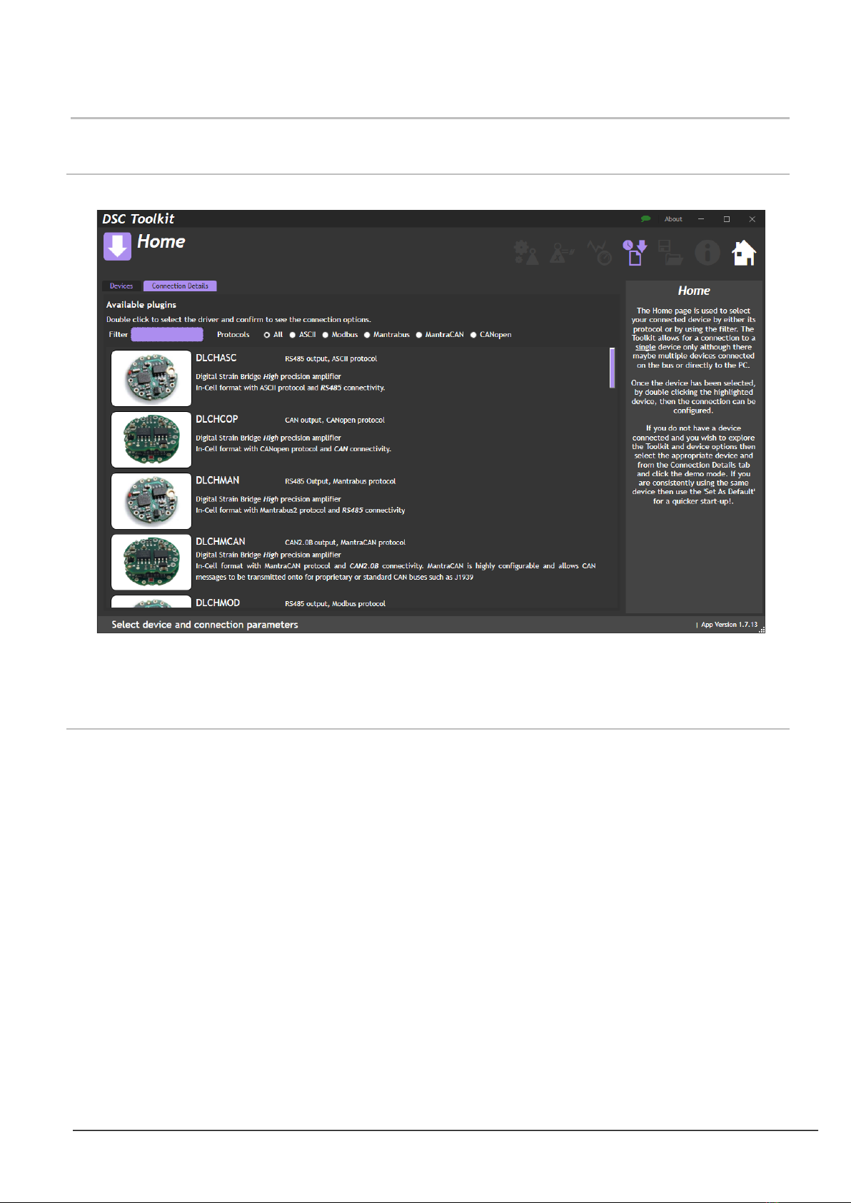
Home
Devices
Here you can select the device that you wish to connect to. The full DSC/DLC product list is quite long so you can
reduce it either by manually applying a text filter or selecting the required protocol at the top.
Double click on the required device and you then move to the relevant Connection Details tab. (See below)
Connection Details
There are five different communication protocol types: ASCII, Modbus, Mantrabus, MantraCAN and CANopen.
Once you have selected you correct product (see above) you will go to the relevant connection page.
Other manuals for DSC
1
This manual suits for next models
17
Table of contents
Other Mantracourt Media Converter manuals


Popular Media Converter manuals by other brands

Erma Electronic
Erma Electronic SSI 9001 instruction manual

MultiDyne
MultiDyne FMX-GE-1000 instruction manual

HEIDENHAIN
HEIDENHAIN LIDA 573 Mounting instructions

Virginia Diodes
Virginia Diodes WR5.1 Operational manual

Nakanishi
Nakanishi NSK Varios 970 Operation manual

Interlogix
Interlogix MCR300-1T user manual


