flamco LogoMatic G2 User manual

www.flamcogroup.com/manuals
LogoMatic G2
ENG Installation and operating instructions
UC / MC/ MC-UC, electronically controlled, app-controlled
S-/M-/L-line as complete or ready-to-use stations
Manual LogoMatic G2
2
Acronyms
CW Domestic water cold
HW Domestic water hot
FL Heating flow line
RL Heating return line
MC Mixed circuit
UC Unmixed circuit
DWC Domestic water circulation
L Length
HC Heating circuit
MT Male thread
HE High-eiciency
BFD ball valve for filling and draining
prim. Primary circuit
sec. Secondary circuit
WF Width across flats
DWH Domestic water heater
Htg. Heating
BP Backflow preventer
Chap. Chapter
STM Safety temperature monitor
ETS External temperature sensor
UFH Underfloor Heating
CS Complete stations

We reserve the right to change designs and technical specifications of our products.
3
ENG
Table of contents
1. Safety instructions .................................................................................................... 4
1.1 Intended use ........................................................................................................................5
1.1.1 Use for intended purpose ................................................................................................................ 5
1.1.2 Improper use .................................................................................................................................... 6
1.2 Device designation...............................................................................................................6
1.3 Information on hazards........................................................................................................7
1.4 What to do in the event of breakdown or leaks.....................................................................8
1.5 Spare and wear parts ...........................................................................................................8
1.6 Requirements on trained engineers......................................................................................8
1.7 Liability................................................................................................................................8
2. Functional description ............................................................................................... 9
3. LogoMatic G2 - electronically controlled heating interfacestation ............................... 10
3.1 Article numbers for prefabricated stations .........................................................................10
3.2 Technical data....................................................................................................................12
3.3 Design and components.....................................................................................................13
3.4 Installation.........................................................................................................................15
3.4.1 Insulated surface-mounted variants with multi-part thermal insulation................................... 17
4. Individual station components (depending on variant)............................................... 20
4.1 Optional heat meter installation ........................................................................................20
4.2 Optional domestic cold water meter installation................................................................21
4.3 Zone valve for heating circuit .............................................................................................22
4.3.1 Optional safety temperature limitation and actuator.................................................................. 23
4.4 Dirt trap and thermostatic circulation bridge .....................................................................24
4.5 Dierential pressure regulator ...........................................................................................25
4.7 Mixed heating circuit (depending on variant) ............................................................................. 27
4.7.1 High-eiciency heating circuit pump............................................................................................ 28
4.8 Hot water throttle ..............................................................................................................29
4.9 Domestic water circulation with pump and BP...................................................................30
4.10 Optional accessories ..........................................................................................................32
4.10.1 Heating circuit manifolds.............................................................................................................. 33
4.10.2 Terminal strip for underfloor heating circuit manifolds.............................................................. 34
4.10.3 Static heating circuit (with MC-UC variants) and simultaneous heating circuit distribution.... 35
4.10.4 Ball valve sets, DN 20 straight (BV) ............................................................................................... 36
4.10.5 Mounting rails with ball valves (FFR)............................................................................................ 36
4.10.6 Cover hoods and cladding housing.............................................................................................. 37
4.10.7 Sample configurations (or complete stations CS) ....................................................................... 39
5. Commissioning........................................................................................................ 42
5.1 Flushing and filling.............................................................................................................42
5.2 Initial start-up ....................................................................................................................42
6. Maintenance and service.......................................................................................... 43
7. Pressure loss characteristic curves............................................................................ 44
8. Troubleshooting ...................................................................................................... 46
9. Spare parts ............................................................................................................. 47
Manual LogoMatic G2
4
1. Safety instructions
Please follow these safety instructions carefully to prevent hazards and injury to persons
and property.
These operating instructions are primarily designed for the safe use and installation
ofthe device and make no claims to completeness.
These operating instructions describe the functionality of the device and are intended
to provide information about the required safety instructions and to draw attention to
possible hazards. If you should become aware when reading them of any inaccuracies
or points requiring clarification, please contact the manufacturer. Further technical
information can be found in the other applicable documents and must also be observed.
These operating instructions are valid only for the described device and are not subject to the
manufacturer’s revision service. The sketches and drawings they contain are not to scale.
• Keep the operating instructions within easy reach of all employees instructed to carry out work
onthe device so that they can refer to them as required.
• Keep the operating instructions in a clean, complete and legible condition throughout the entire
period of use.
• Read the operating instructions before working on the device for the first time and consult them
whenever uncertainties or doubts arise as to how the device should be handled.
• Should you come across any discrepancies when reading these operating instructions or should
anything remain unclear, please contact the manufacturer.
Target group
These instructions are intended exclusively for authorised trained experts.
Only trained experts or installers authorised by the respective competent utility companies
arepermitted to work on heating systems and domestic water, gas and electric circuits.
Regulations
When carrying out work, you must comply with:
• The statutory accident prevention regulations,
• The statutory environmental protection regulations,
• The German Employer's Liability Insurance Association regulations,
• The pertinent safety requirements of DIN, EN, DVGW, TRGI, TRF and VDE,
• ÖNORM, EN, ÖVGW-TR Gas, ÖVGW-TRF and ÖVE,
• SEV, SUVA, SVGW, SVTI, SWKI and VKF
• and all new and regionally applicable regulations and standards

We reserve the right to change designs and technical specifications of our products.
5
ENG
Instructions for working on the system and system parameters
• Disconnect the system from the mains and monitor it to ensure that no voltage is being supplied
(e.g. at the separate cut-out or a main switch).
• Secure the system against being restarted.
•WARNING: Risk of scalding: If media temperature > 60 °C
• Heating system parameters: Permissible nominal pressure rating: PN10
Max. permissible operating temperature: 100 °C
• Sanitary system parameters: Permissible nominal pressure rating: PN10
Min. CW pressure 1 bar
Max. permissible operating temperature: 100 °C
Optimum operating pressure: 2 bar
• The devices must be installed in enclosed, frost-free spaces.
• Any noise emissions or radiant heat from the station must be taken into account in the choice
ofinstallation site.
• Observe the safety areas in accordance with EN 60529 when designing and installing the system
• Any sanitary installation must be made safe in compliance with DIN 1988 or DIN EN 806, i.e.
withthe use of a safety valve and, where applicable, an expansion vessel.
Note:
In the case of anticipated high primary temperatures of >60 °C, thermostatic scalding protection
must be ensured at the domestic hot water draw-o point in order to restrict the outlet temperature
(in the event of a power failure).
The potential equalisation or protective earthing is achieved via the controller and the 230 V
power supply.
1.1 Intended use
1.1.1 Use for intended purpose
Heat interface stations are used to transfer heat between the supply network and the heat consumer.
Heat interface stations may only be used for this purpose in compliance with the maintenance and
operating instructions and all relevant standards and regulations.
All instructions in the operating instructions must be followed and the maintenance plan adhered to.
Any deviation from the intended use may cause hazards and is not permitted.
The LogoMatic heat interface station provides a residential station with space heating and domestic
hot water according to the continuous flow principle. Any additional or alternative use is impermissible
and regarded as an unintended use.
Appropriate use in heating and domestic water systems in accordance with the applicable DIN standards.
Installing and operating the assembly incorrectly will invalidate any warranty claims. The shut-o valves
may only be closed by an approved specialist when servicing, otherwise the safety valves will not work.
Manual LogoMatic G2
6
The LogoMatic heat interface station is not suitable for installation in adjacent recreation rooms
orbedrooms.
An avoidance of sound transmission in and to adjacent walls or rooms must be observed!
Caution:
Do not make any changes to the electrical components, the design of the system orthe
hydraulic components! This would adversely impact on the safe function ofthesystem.
Instructions concerning the place of use:
Before our products are used, they must be checked for suitability for the planned application
inquestion.
In particular for heating systems, please take into account the properties of the heating water
inaccordance with VDI 2035 to protect the heating system and, for domestic water applications,
thewater quality at the place of use.
In the case of critical water qualities, please take suitable measures where necessary (e.g. water
treatment) to prevent functional impairment and/or damage, e.g. corrosion damage.
In particular, please check the permissible limit values, e.g. electrical conductivity, the pH value,
theGerman hardness level and the ammonium concentration.
Furthermore, in Germany all applicable norms, regulations and guidelines specific to the federal
states must be taken into consideration, alongside the instructions in the applicable installation
andoperating manuals.
Further information can be found in the download section of www.flamcogroup.com.
1.1.2 Improper use
Using the device in any way that does not correspond to the intended use may cause hazards
andisnot permissible.
In particular, the following are not allowed:
• The throughflow of liquids other than water with the described properties
• Use of the device without prior knowledge of the operating instructions
• Use of the device without legible warning and information signs Use of the device
inadefectivecondition
1.2 Device designation
Designation: LogoMatic G2
Function: Transfer of thermal energy to the heating supply and hot water preparation
Type: Prefabricated/complete stations as S-/M-/L-Line in dierent versions
(UC, MC, MC-UC)
Manufacturer: Meibes System-Technik GmbH

We reserve the right to change designs and technical specifications of our products.
7
ENG
1.3 Information on hazards
The safety and warning information draws attention to residual hazards that cannot be avoided
due to the design and construction of the device. Please always observe the measures shown
foravoiding these hazards.
Never alter or modify the station by yourself. Such work may only be carried out by qualified
specialist personnel. This also applies to the electrical installation.
When the system is in operation, water-carrying components will be hot. Touching
these system components can lead to scalding. The interface station and its heat-
carrying components are mostly equipped with permanent insulation. This insulation
not only prevents unnecessary thermal losses but also protects against accidental
contact and burns. The insulation must therefore only be removed for maintenance
orrepair purposes and replaced correctly on completion of such work.
Warning: For some components and station variants, no insulation is fitted at the factory. You must
therefore take extra care to avoid accidental contact.
The system is operated using hot, high-pressure water, which can cause scalding on contact.
Youshould therefore open the bleed or drain valves carefully and not work on pressurised parts.
The control components (controller, pumps, etc.) are powered by mains voltage.
Therefore, always ensure the station is disconnected from the mains supply
when carrying out any maintenance orrepair work. Secure the system against
unauthorised operation.
Life-threatening electric shocks can be caused by spray or splashing water. Escaping water can also
render the safety devices inactive.
Any changes made to the station that have not been authorised by the manufacturer will invalidate
any warranty claims.
Residual hazards:
The equipment has been built according to the state of the art and in accordance with recognised
safety regulations. The following residual hazards may arise during installation, commissioning,
maintenance and disassembly:
Warning: Risk of scalding from high media temperature
• Work particularly carefully.
• Use safety clothing (e.g. heat-resistant protective gloves).
• If necessary, surfaces must be thermally cleared before commencing work.
• Use stipulated tools.
Hazard: Risk of injury from electrical voltage
• Only instructed, qualified electricians are permitted to work on electrical equipment.
• Electrical installation spaces must always be kept locked.

Manual LogoMatic G2
8
1.4 What to do in the event of breakdown or leaks
• Close media lines using the appropriate valve.
• Contact a suitably trained expert or customer service of the manufacturer.
The device will only be cleared for operation again when the trained engineer has remedied the
fault and restored the device to its intended condition.
1.5 Spare and wear parts
All spare and wear parts used must correspond to the technical requirements defined by Meibes
System-Technik GmbH. This is guaranteed only with genuine spare parts. The manufacturer is not
liable for damage caused by the use of unapproved spare and wear parts or ancillary materials.
Appropriate spare and wear parts can be found in the other applicable documents.
1.6 Requirements on trained engineers
A trained expert must have undergone advanced technical training and have suicient experience
to independently perform complicated tasks or work associated with residual hazards. Such
experience will in each instance refer to a specialism, e.g. maintenance, working on electrical
systems, systems mechanic for sanitary, heating and air conditioning technology. In preparation
forimpending work, a trained expert must be able to correctly estimate the feasibility, risks and
hazards as well as the equipment required. A trained expert is expected to be able to understand
complex and minimally detailed plans and descriptions and to use appropriate means to obtain
anymissing and essential detailed information. The trained expert must be able to restore and
check the intended condition of a system. A worker can be a trained expert in several fields.
For work on the electrical equipment, only trained electricians according to DGUV regulation 3 may
be used.
1.7 Liability
We reserve all copyrights to this document. Misuse thereof, in particular reproduction or disclosure
to third parties, is prohibited. These installation and operating instructions must be given to the
customer. The technician carrying out and/or authorising the work (e.g. installer) must explain the
functioning and operation of the system to the customer in a readily comprehensible way.
We reserve the right to change designs and technical specifications of our products.
9
ENG
2. Functional description
The electronically controlled LogoMatic G2 heat interface stations provide a residential station
with domestic hot water and heating. The domestic water is heated via a stainless-steel plate
heatexchanger and electronic control valves based on the continuous flow principle. The station
must simply be connected to the flow and return lines and the cold water line.
The integrated controller is operated at 230 V / 50 Hz. The mains fuse is 10 A.
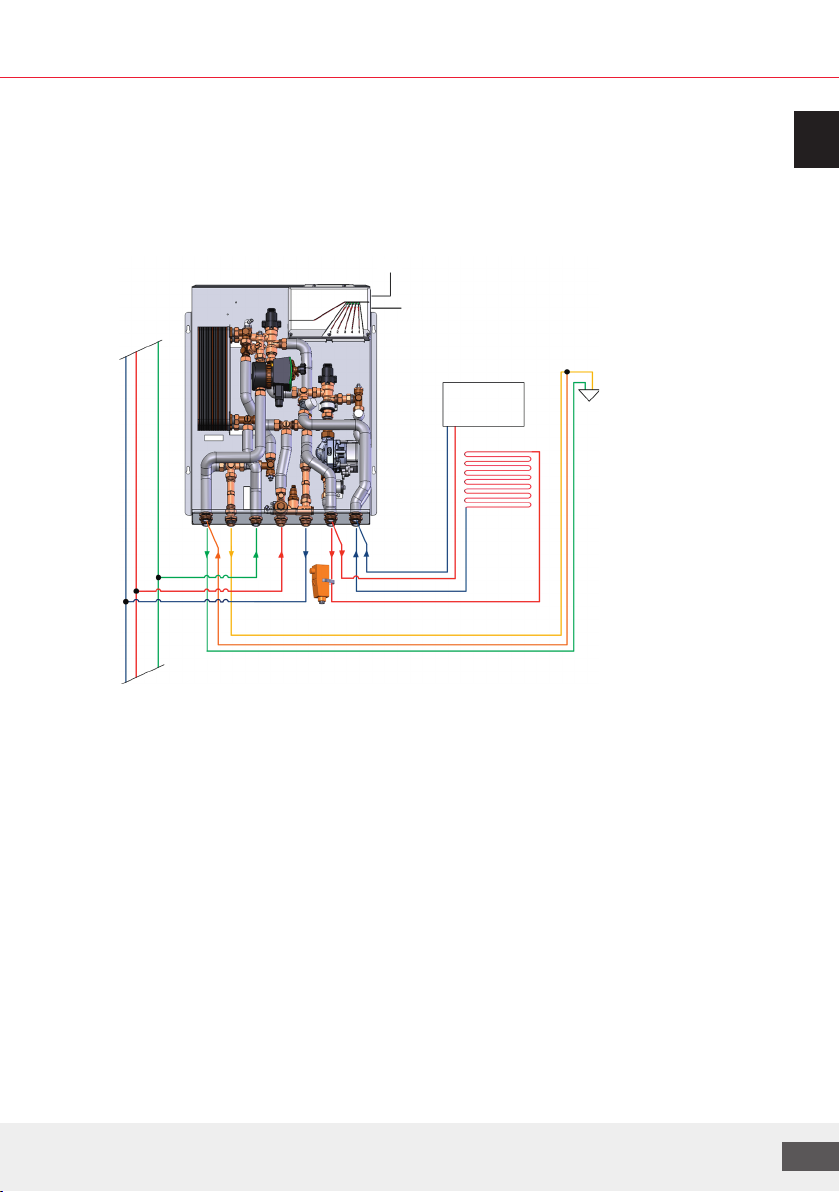
Fig.: Example
integration of a
LogoMatic G2 MC-UC-
DHWC station with
mixed HC and optional
STM and ETS
Note concerning LM G2 Weather-driven heating circuit control via optional external temperature
sensor (ETS). STM with electrothermal actuator can be ordered as an optional extra. (see chap. 4.3.1)
A dierential pressure regulator in the station allows for hydraulic balancing of the heating circuits.
The zone valve integrated in each device also permits adjustment of the dwelling heating circuit.
Installing a living space or reference room controller (option) allows the independent operation
ofthe dwelling heating circuit.
Adaptors for water meter and heat flow meter (L = 110 mm, 2 x 3/4" MT) are included in the scope
ofsupply of each station.
Note: Additional accessories or options can be found in the current price list (ETS, STM etc.)
Description of the hot water preparation process:
Heating takes place at a preset control value (50 °C; with circulation 60 °C). The control value can
beadjusted as required by the factory customer service team.
If the flow meter identifies a draw-o, the hot water preparation is adjusted to the preset setpoint
value via the control valves.
ETS
STM

Manual LogoMatic G2
10
3. LogoMatic G2 - electronically controlled heating
interfacestation
3.1 Article numbers for prefabricated stations
Art. no. keys for Logomatic G2 prefabricated stations
Example:
Art. no.
Identification
number
Model Unit characteristic/ abbreviation
M11114.XYZ
Heating
type
X=
4UC for an unmixed HC
5MC for a mixed HC
6MC-UC for one mixed and one unmixed HC
Performance
classes
Y=
_/0 S-Line
as steel version for FM/SM F/S1M-Line
2L-Line
3S-Line
as insulated version for SM SI4M-Line
5L-Line
Domestic water
circulation
Z=
_without DWC
with copper-soldered PHE CU
1with DWC
(DHW-C)
2without DWC
with sealed copper-soldered PHE SX
3with DWC
(DHW-C)
Note: Suitable complementary products are available as optional extras for prefabricated stations.
Incontrast to complete stations (CS), where e.g. ball valves, manifold for floor heating circuits or hoods
are included (see chap. 4.10.7).
Prefabricated stations with copper-soldered PHE (without DWC)
Steel versions for SM or FM and
insulated. Surface-mounted*
versions
S-Line M-Line L-Line
LogoMatic G2 variants 12 L/min (35 kW) 17 L/min (46 kW) 22 l/min (60kW)
UC M11114.4/-43 M11114.41 /-44 M11114.42 /-45
MC M11114.5/-53 M11114.51 /-54 M11114.52 /-55
MC-UC M11114.6/-63 M11114.61 /-64 M11114.62 /-65

We reserve the right to change designs and technical specifications of our products.
11
ENG
Prefabricated stations with copper-soldered PHE and DWC
Flush/ and surface-mounted*
versions
S-Line M-Line L-Line
LogoMatic G2 variants 12 L/min (35 kW) 17 L/min (46 kW) 22 l/min (60kW)
UC M11114.401 /-431 M11114.411 /-441 M11114.421 /-451
MC M11114.501 /-531 M11114.511 /-541 M11114.521 /-551
MC-UC M11114.601 /-631 M11114.611 /-641 M11114.621 /-651
Prefabricated stations with sealed PHE (without DWC)
Flush/ and surface-mounted*
versions
S-Line M-Line L-Line
LogoMatic G2 variants 12 L/min (35 kW) 17 L/min (46 kW) 22 l/min (60kW)
UC M11114.402 /-432 M11114.412 /-442 M11114.422 /-452
MC M11114.502 /-532 M11114.512 /-542 M11114.522 /-552
MC-UC M11114.602 /-632 M11114.612 /-642 M11114.622 /-652
Prefabricated stations with sealed PHE and DWC
Flush/ and surface-mounted*
versions
S-Line M-Line L-Line
LogoMatic G2 variants 12 L/min (35 kW) 17 L/min (46 kW) 22 l/min (60kW)
UC M11114.403 /-433 M11114.413 /-443 M11114.423 /-453
MC M11114.503 /-533 M11114.513 /-543 M11114.523 /-553
MC-UC M11114.603 /-633 M11114.613 /-643 M11114.623 /-653
* Any type of enclosures (steel or also insulating enclosures) for prefabric stations must be ordered
separately. They are not included in the named article numbers.

Manual LogoMatic G2
12
3.2 Technical data
Dimensions:
Prefabricated station without hood SM/
FM variant
Insulated SM variant
Height x Width x Depth (H x W x D in mm)
576 x 775 x 110 (depending on design)
approx. 556 x 990 x 163
Bottom connections ¾"
Heating output 10 kW (20 K)
Hot water output
35; 46 or 60 kW (in the case of domestic water heating
from 10 to 50 °C und primary nominal FL temp.), draw-o
volume 12; 17 or 22 l/min
Nominal flow line temp. (primary) 65 °C
Application limits:
Max. flow line temp. (primary) 100 °C
Permissible nominal pressure rating
(primary):
PN10
Max. dierential pressure(primary): 2.5 bar
Min. dierential pressure(primary): 0.03 bar
The factory setting of the dierential
pressure regulator:
10 kPa
Max. temp. (sanitary) 100 °C
Permissible nominal pressure rating
(sanitary):
PN10
Min. operating pressure (sanitary): 1 bar
We reserve the right to change designs and technical specifications of our products.
13
ENG
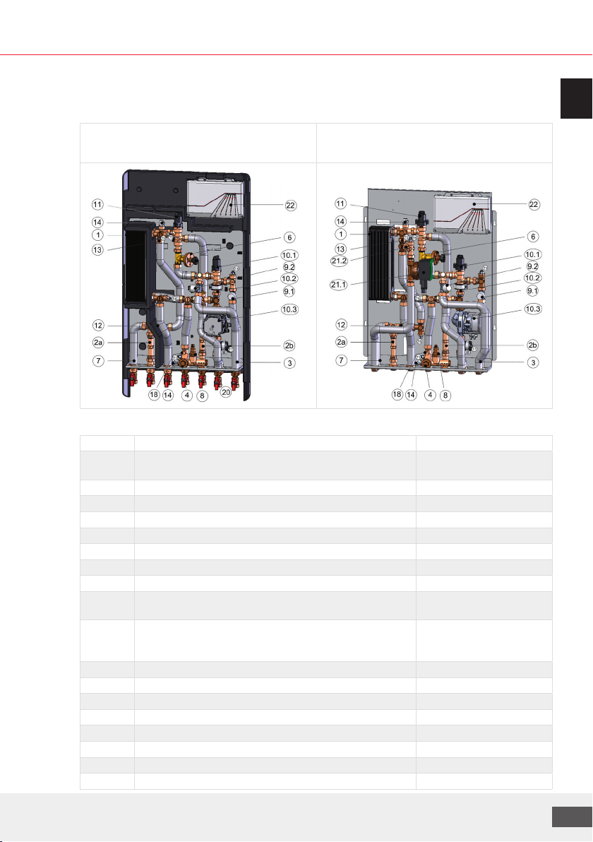
3.3 Design and components
example representations:
LogoMatic G2 MC-UC, insulated version
e.g. with optional ball valves
LogoMatic G2 MC-UC, steel version
e.g. as DWC version
Legend
No. Components Comment
1 Plate heat exchanger, stainless steel, copper soldered/copper
soldered and sealed
24 / 40 /60 plates
2a Adaptor for the cold water meter (L = 110 mm, 2 x ¾" MT)
2b Adaptor for the heat meter (L = 110 mm, 2 x ¾" MT)
3 Insulated stainless steel corrugated pipe
4 Dirt trap, sealed with plug
6 Dierential pressure regulator DN15 (5-25 kPa) Kvs=1.6
7 Cold water connection to dwelling
8Thermostatic circulation bridge, adjustable from 35 °C to 65 °C for heat retention function
9.1 / 9.2 Lower part of control valve ¾", depending on variant for MC/UC Zone valves for dwelling
heating circuits
10 Mixed circuit with (10.1) motorised control valve, type Mut
VDE ML and (10.2) backflow preventer (BP) and (10.3) HE
pump type GF UPM3 hybrid 15-70 130
(10.2), (10.3) only for MC
variants
11 Control valve, type Mut, VDE ML with servomotor
12 Flow sensor ¾", type Sika VTY10 1 - 30 l/min
13 Flow controller, depending on variant (not available with L-Line)
14 Bleeding/drainage plugs ½" heating-system side
18 M10x1 coupler for heat meter immersion sleeve f. optional. HFM
20 Shut-o ball valve ¾" (union nut x ¾" FT) item-specific equipment
21 (21.1) Domestic water circulation pump with (21.2) BP item-specific equipment
22 Control and switching module LogoTronic HIU controller

Manual LogoMatic G2
14
Hydraulic diagram
LogoMatic G2 UC LogoMatic G2 MC-UC-DHWC
(e.g. with optional DWC)
Legend: Connections ¾" MT (without optional ball valves) UC MC MC-UC
ACold water outlet for dwelling, (second CW connection) A A A
BDomestic hot water outlet for dwelling (HW) B B B
CCold water inlet building connection (CW) C C C
D Heating flow line building connection (FL heating) D D D
EHeating return line building connection (RL heating) E E E
F1/F2 Heating flow line for dwelling heating circuit (FL dwelling), F1-MC / F2-UC F2 F1 F1/F2
G1/G2 Heating return line for dwelling heating circuit (RL dwelling), G1-MC / G2-UC G2 G1 G1/G2
ZDomestic water circulation Z (depending on variant) - Z Z
Overview of sensors/actors designations
Temperature sensors (2-wire) UC MC MC-UC
T1 Flow line Primary side T1 T1 T1
T2 Return line T2 T2 T2
T3 Return line MC T3 T3
T4 Domestic hot water Secondary side PHE outlet T4 T4 T4
T5 CW (and DWC if available) Secondary side PHE inlet T5 T5 T5
T7 Flow line MC T7 T7
Valves and pumps (3-/ 4-wire)
V1 Return line, primary side DWH/heating V1 V1 V1
V2 Heating circuit return line (and mixing valve in case of MC) V2 V2 V2
V3 Zone valve UC Servomotor, optional V3 V3
V4 Zone valve MC Servomotor, optional V4 V4
P1 Heating circuit pump MC P1 P1
P2 DWC pump with optional DWC P2 P2
Primary UC Primary UCMC
We reserve the right to change designs and technical specifications of our products.
15
ENG
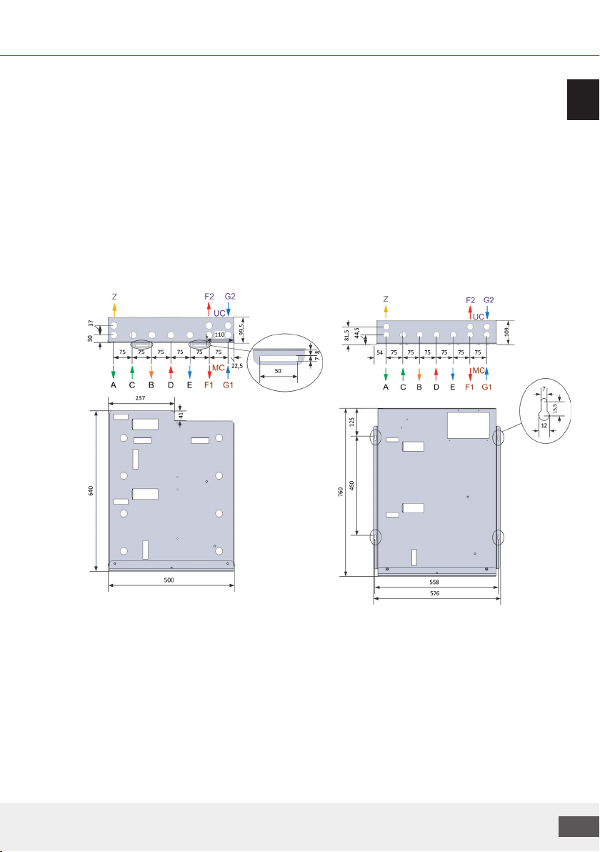
3.4 Installation
Please follow the safety instructions in this document and any additional assembly instructions
of other components during installation! Installing and operating the stations incorrectly will
invalidate any warranty claims.
Installation options: depending on variant, either surface- (SM) or flush-mounted (FM) on a wall.
Note: for FM variants, optional insulating plates and strips are available separately.
Dimensions of base plates (sheets without insulation):
for insulated variant (SM isolated/ SI) For steel variant (SM/FM)
Manual LogoMatic G2
16
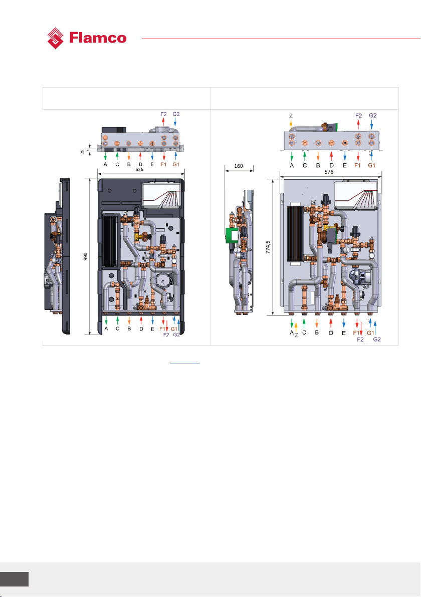
Unit dimensions and connections:(including example representations)
LogoMatic G2 MC-UC-SI
(shown with insulation, without front covers)
LogoMatic G2 MC-UC-DHWC-FS
(Variant with DWC)
Note: For the connections legend, see chap. 3.3
For information on installation depths with dierent equipment and product combinations, see
chapter 4.10.6.2.
(without
DWC
110mm)
MC MC
MC
MC
UC
UC
UC UC

We reserve the right to change designs and technical specifications of our products.
17
ENG
3.4.1 Insulated surface-mounted variants with multi-part thermal insulation
Dimensions of SM thermal insulation and retaining plate (in mm):

Manual LogoMatic G2
18
Construction and installation steps
1. Attach retaining plate to wall
(observe the following dimensions)
2. Hang LogoMatic G2 station with rear
insulation and stabilisation plate
onretaining plate
3. Carry out hydraulic and electrical connections
4. Commissioning (see chap. 5)
5. Attach front insulation parts
Legend
Pos. Description
1 Wall retaining plate
2.1 Rear insulation top
2.2 Rear insulation bottom
2.3 Stabilisation plate
3 Aperture for hydraulic connections
5 Front insulation
Dimensions of retaining plate (pos. 1) for wall mounting:
Diam. 12mm
We reserve the right to change designs and technical specifications of our products.
19
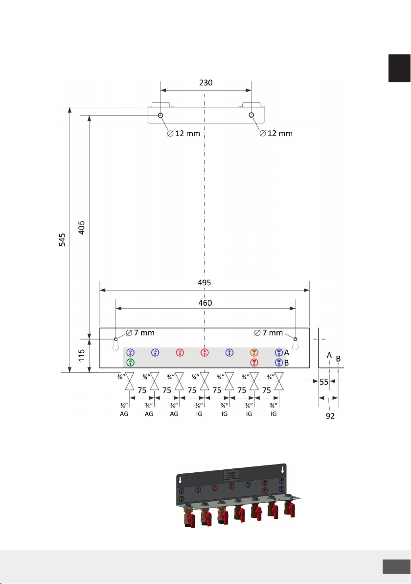
ENG
Drill hole dimensions for station installation (for insulated SM variant) and use of optional mounting
rail (M10203.762, see also chap. 4.10.5) with throughflow ball valves:
Note: The connections (drinking water, heating) are each labelled with the appropriate symbol.
Warning!
Use plastic plugs only to fix the
ball valves.
Manual LogoMatic G2
20
4. Individual station components (depending on variant)
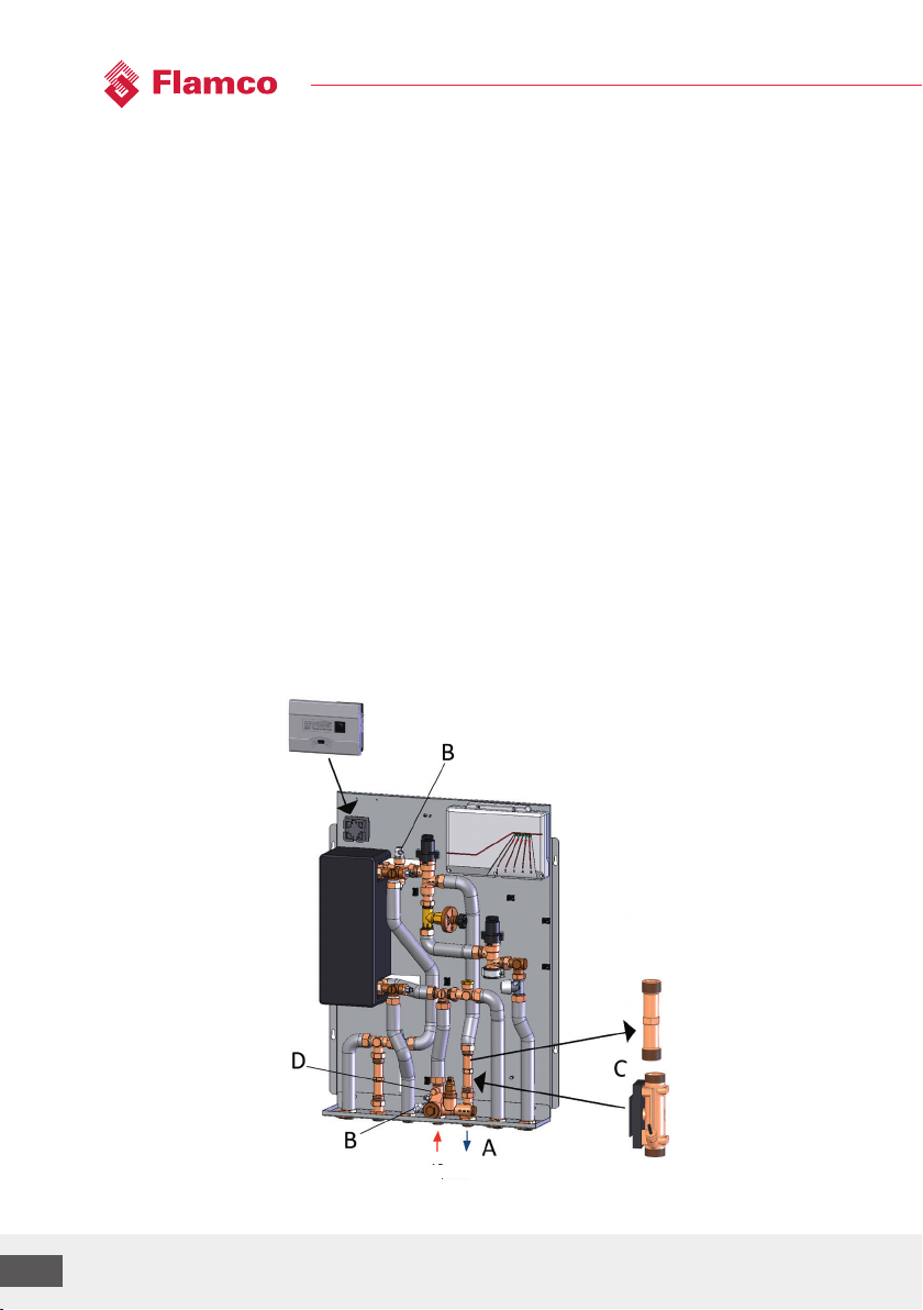
4.1 Optional heat meter installation
The heat meter may only be installed once the entire heating system has been flushed through.
LogoMatic G2 stations are fitted with an adaptor (L = 110 mm, 2 x 3/4") for a heat meter which must
be removed before the heat meter is installed.
The corresponding instructions for the HFM must be followed.
Procedure:
1. Close all shut-o valves "A" in the station (if present).
2. Lower the system pressure by opening bleeding device "B". WARNING: Water may leak from
thesystem.
3. Release the screw fittings on adaptor "C". WARNING: Water may leak from the system. (The
station can be drained using bleeding device "B" below or the BFD ball valves, where installed.)
4. Remove the adaptor and insert the heat meter and screw in place. NOTE: Observe the direction
of flow, use seals.
5. Remove the M10x1 plug at "D" and screw in and seal the heat meter supply sensor.
6. Once the work is complete, re-open the shut-o valves and use the bleeding devices to bleed
the station. Perform a leak-tightness check.
FL RL
prim.
Table of contents
Other flamco Industrial Equipment manuals


Popular Industrial Equipment manuals by other brands

Trane
Trane Tracer CH530 Installation, operation and maintenance

weha
weha Transport rack for kitchen tops quick start guide

Zirkon zahn
Zirkon zahn titanium spectral-colouring anodizer Operator and maintenance manual

MAV
MAV 5061 Installation and Removal Instructions

ABB
ABB HT611934 Operation manual

WALTERSCHEID
WALTERSCHEID ZWL 30 Installation and operating instructions


National Instruments
National Instruments NI 9402 Getting started

iOptron
iOptron iPolar Operation manual

ABB
ABB RELION 650 SERIES Product guide

REGULA
REGULA 7708 operating manual

Dixon
Dixon 200-PV-9 Maintenance & Operating Intructions

PCB Piezotronics
PCB Piezotronics HT356A01 Installation and operating manual