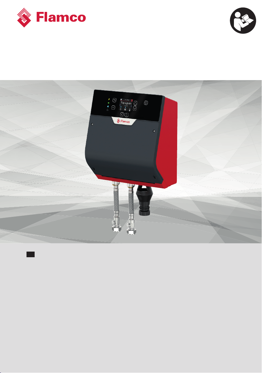
flamco FlexFiller Direct G4 User manual
www.flamcogroup.com/manuals
FlexFiller Direct G4
ENG Installation and operating manual

Manual FlexFiller Direct G4
2
Table of Content
1. Warranty ................................................................................................................ 4
1.1 Conditions of warranty ..........................................................................................5
2. Liability ................................................................................................................. 5
3. Copyright ............................................................................................................... 5
4. About this manual .................................................................................................. 6
4.1 Conventions symbols in this manual........................................................................6
4.2 Typography ..........................................................................................................6
4.3 Where to find more information?.............................................................................6
5 Safety .................................................................................................................... 7
5.1 Incoming goods .....................................................................................................7
5.2 Operations location ...............................................................................................7
5.3 Electrical ..............................................................................................................7
5.4 Sta qualification..................................................................................................8
6 Product description............................................................................................... 10
6.1 Operating principle.............................................................................................. 10
6.2 Technical datasheet ............................................................................................. 11
7 Installation requirements....................................................................................... 12
7.1 Installation diagram ............................................................................................ 13
7.2 Clearance requirements ....................................................................................... 14
7.3 Hydraulic connections.......................................................................................... 15
7.4 Controller........................................................................................................... 16
7.5 Connectivity options............................................................................................ 18
8 Electrical installation............................................................................................. 19
8.1 Alarm installation................................................................................................ 19
9 Operation............................................................................................................. 20
9.1 Shut-down procedure .......................................................................................... 21

We reserve the right to change designs and technical specifications of our products.
3
ENG
9.2 Restarting........................................................................................................... 21
10 Maintenance ......................................................................................................... 22
10.1 Maintenance intervals.......................................................................................... 22
10.2 Visual inspection ................................................................................................. 23
10.3 Interrogate controller .......................................................................................... 23
10.4 Test unit operation .............................................................................................. 24
11 Decommissioning / Dismantling.............................................................................. 24
Appendix 1. Icon library ................................................................................................. 25
Appendix 2. Markings .................................................................................................... 28
Appendix 3. Troubleshouting guide ................................................................................. 29
Manual FlexFiller Direct G4
4
1. Warranty
The Flamco warranty on equipment supplied covers manufacturing defects, under our standard
terms and conditions of sale, where items with a proven manufacturing defect are replaced at the
point of sale.
In some circumstances it will be appropriate for an engineer visit to review or inspect the product
under warranty. For all engineer visits, requested under alleged warranty, a purchase order is
required to cover work and time that is deemed to be outside of the warranty agreement. If no
recognised commissioning, by a Qualified Person, has taken place, then the warranty may be null
and void. If the unit is identified with a manufacturing defect within the warranty period, then no
charge is made for correcting the defect.
Flamco reserve the right to supply a replacement product in lieu of an engineer visit. Removal and
reinstallation costs, along with consequential losses are not covered by this warranty agreement.
Flamco equipment is manufactured to order and is marked with a unique serial number, allowing
traceability to both individual model configurations and the date of manufacture. The warranty,
against manufacturing defects, is for 30 months from date of manufacture or 2 years from date of
confirmed commissioning, whichever is sooner.
For the warranty to be valid it is also taken that there is an appropriate safety valve on the wider
system protecting the equipment. That the equipment is undamaged at the time of installation. That
the equipment is not exposed to adverse environmental conditions. That the equipment is stored
and installed in a frost-free area. That these operating and maintenance instructions are followed.
That the equipment is used for the purpose for which it was designed.
An extended warranty is available by purchasing a separate Flamco service agreement.
Service Agreement Standard Warranty Extended Warranty
3 year contract 2 years 1 year
5 year contract 2 years 3 years
For general Terms and Conditions of this sale, see General Conditions of Sale Flamco Group on the
Flamco website in link below:
https://flamcogroup.com/ex-en/page/terms-and-conditions
We reserve the right to change designs and technical specifications of our products.
5
ENG
1.1 Conditions of warranty
It is a requirement of your local water authority to disclose
the installation location.
To make this easy, you must register your product, activate your warranty
and register with your local water authority on our website at:
https://flamcogroup.com/warranty-registration
Failing to disclose the installation location of this product with your local water authority
will lead to invalidation of The Flamco warranty described above.
Warranty claims or queries can be directed to:
Service Department service@flamco.co.uk
Flamco Limited +44 (0) 1744 744 744
Washway Lane
St Helens
Merseyside
WA10 6PB
2. Liability
All technical specifications, data and instructions for executable actions and contained herein are
correct at time of publication. This information is the result of our current findings and experience
to the best of our knowledge. We reserve the right to make technical changes subject to the future
development of the Flamco product referred to in this publication. Hence no rights may be derived
from technical data, descriptions and illustrations. Technical pictures, drawings and graphs do not
necessarily correspond to the actual assemblies or parts as delivered. Drawings and pictures are not
to scale and contain symbols for simplification.
3. Copyright
All documentation is protected by copyright. Distribution or other forms of reproduction of
documents, even extracts, exploitation or notification of the contents hereof is not permitted, where
not otherwise specified. Infringements are liable to prosecution and payment of compensation. We
reserve the right to exercise all intellectual property rights.

Manual FlexFiller Direct G4
6
4. About this manual
The following pages list the information, specifications, measures and technical data that allow the
relevant personnel to use this product safely and for the intended purpose.
Responsible persons or those engaged by them carrying out the required services must read this
manual attentively and understand it.
Such services include:
Storage, transportation, installation, electrical installation, commissioning and re-starting,
operation, maintenance, inspection, repair and dismantling.
Where the product is to be used in plants/facilities which are not required to comply with local or
harmonised regulations, this document is purely for informative and reference purposes.
As this unit may be subject to unlimited inspection from the local water authority at all times, this
manual must be kept in the immediate vicinity of the installed unit, at least within the confines of the
operations room. Installation classification 2 according to the Annex R of 60730-1
Disregard or lack of attention to the information and measures contained in this manual may pose
a hazard to people, animals, the environment and tangible assets. Failure to observe the safety
regulations and the neglect of other safety measures may lead to significant consequiential loss
4.1 Conventions symbols in this manual
WARNING – Important safety related information intended to prevent injury and/or
damage to the equipment, system or property.
IMPORTANT - Important information intended to ensure that the equipment functions
correctly
USEFUL – Useful information which may be helpful, but is not necessarily required for the
unit to function correctly.
4.2 Typography
This manual makes use of dierent typography to identify dierent types of information.
Italics Key words and phrases
(Round Brackets) Used to identify a button on the digital controller
[Square Brackets] A parameter on the digital controller
<Inequality symbols> A message/fault code displayed on the digital controller
4.3 Where to find more information?
For the Quick Start Guide and further documentation in various languages, visit:
www.flamcogroup.com/manuals
For further information please visit the Flamco Limited Website at the following URL:
www.flamco.co.uk
We reserve the right to change designs and technical specifications of our products.
7
ENG
Alternatively, to contact other Flamco locations, please see the contact page in Appendix 4: Contact
5 Safety
This equipment is intended to fill and/or top-up sealed water-based heating and cooling systems, in
which temperature-induced changes in the volume of the system water (the heat transferring agent)
is governed by a separate expansion vessel and safety relief valve.
This product is suitable and appropriate for the operation in heat generating systems according to
BS7074, BSEN 12828, BSEN 12952 and BSEN 12953.
The Principal / Operator, will need to consult with a local authorities on any additional safety
measures that are required.
5.1 Incoming goods
The items delivered must be compared against the items listed on the shipping note and inspected
for conformity. If not in line with the documentation or if the delivery is incorrect in another way,
the product must not be used. The goods may also be warehoused in their packaging. Once it has
been removed from its packaging, the equipment must be put in position, observing standard safety
procedures.
Always check the unit for damage and appropriate markings according to Appendix2:
Markings in this manual.
5.2 Operations location
The responsible person carries the responsibility over the designated plant room that meets all the
requirements stated above.
Definition: Room which meets the applicable European and local regulations, standards and
relevant technical rules and guidelines of the professional associations for this
field of application. For the use of the FlexFiller Direct G4 as prescribed in this
manual these rooms generally contain equipment for thermal generation and
distribution, water heating/cooling and top-up, power source and distribution,
such as measuring, control engineering, control technology and IT.
Access for unqualified and untrained persons must be restricted or forbidden
Unit Internal access
The unit internals can be accessed for service or repair, by a Qualified Person. The unit can only be
accessed by using a specialized tool. Any attempts to access the internals of the unit without the
correct equipment will invalidate the Flamco Warranty and will be classified as use in an improper
manner, according to our General Conditions of Sale.
5.3 Electrical
Electrical equipment inspections, routine inspection
Without prejudice to the considerations of the insurer/Operator, it is recommended that the
electrical equipment of the FlexFiller Direct G4 be inspected and documented together with the
heating/cooling unit no less than every 18 months (see also DIN EN 60204-1 2007).

Manual FlexFiller Direct G4
8
Emergency- STOP / Emergency-OFF
To conform with directive 2006/42/EG an EMERGENCY-STOP facility is to be made available during
installation.
Preferably, use a grounded wall socket for the power supply to the unit. The socket must stay
accessible. If the unit is directly connected to the power supply, make sure the power supply line is
provided with:
• a high-sensitivity dierential switch (30mA) (residual current device RCD)
• a mains isolator switch with a contact gap of at least 3 mm.
When additional security measures with EMERGENCY-OFF devices are required according to the
design and operation of the heat generator, these are to be installed on-site.
Obvious misuse
• Operation at incorrect voltage and/or frequency.
• Use in inappropriate system designs.
• Use of unpermitted installation materials.
Other hazards
• Overload of construction parts by the presence of unpredictable extreme values.
• Operational continuity at risk in the case of changed, non-permissible ambient conditions.
• Operational continuity at risk in the case of safety-control parts being taken out of service or
malfunctioning.
5.4 Sta qualification
Definitions:
• Operator: A person or legal entity who is the owner of the product and uses the aforementioned
product, or is nominated to use it, under the terms of a contractual agreement.
• Principal: The legally and commercially responsible party in the execution of construction
projects. Legally and commercially liable client in the commission of building projects.
• Responsible person: The representative appointed to act by the main contractor or operator.
• Qualified person (QP): A Qualified Person must have undergone advanced technical training
and have suicient experience to independently perform complicated tasks or work associated
with residual hazards. Such experience will in each instance refer to a specific specialism, e.g.
maintenance, working on electrical systems, systems mechanic for wholesome water (potable),
sealed heating/cooling and air conditioning technology. In preparation for impending work, a
Qualified Person must be able to correctly estimate the feasibility, risks and hazards as well as the
equipment required. A Qualified Person is expected to be able to understand complex, minimally
prepared plans and descriptions, and to obtain missing and required detailed information by
suitable means.
The product must be installed by a Qualified Person with regard to the following relevant
requirements:
• The Health and Safety Regulations
• Building Regulations
• IEE Regulations
• Water Supply (Water Fittings) Regulations
• Water By-laws (Scotland)
• Any other by-laws or planning requirements.

We reserve the right to change designs and technical specifications of our products.
9
ENG
All Flamco products should be installed by a Qualified Person with the relevant qualifications
to carry out the required services and be physically and psychologically capable. The area of
responsibility, competence and supervision of personnel is the duty of the Operator.
Operating instructions are transferred by Flamco representatives or others assigned by them during
delivery negotiations or on demand.
Training for the required services, installation, dismantling, commissioning, operation, inspection,
maintenance and repair are part of the training / further education for service engineers of the
Flamco branch oices or named service contractors.
These training courses cover information on required installation conditions, but not their
implementation.
On-site services include transportation, the preparation of an operations room with the requisite
foundation engineering to accommodate the system, and the requisite hydraulic and electrical
connections, the electrical installation for the power source of the expansion automat and
installation of the signal leads for the IT equipment.
Required service Professional group example Relevant qualifications
example
Storage transportation Logistics, transport,
warehousing Transport and warehousing
specialist
Assembly, dissassembly,
repairs, maintance. Re-
commissioning aer adding
or changing components.
Inspection.
Installation and building
services HVAC specialist
First commissioning of
configured control unit
(generic), re-commissioning
aer power cut, operation
(work on the terminal and
Flextronic control unit)
People with operations room
clearance with knowledge
gleaned from this guide.
Electrical installation Electrical engineering Specialist in electrical
engineering/ installation
Initial and re-inspection of
electrical systems Qualified person (QP) with
certfication in Electrical
engineering.
Inspection before
commissioning and
re-inspection of pressure
equipment
Installation and building
services engineering performed
in the context of technical
inspection
Qualified person (QP)
Manual FlexFiller Direct G4
10
6 Product description
The FlexFiller Direct G4 is the most compact, wall-mounted, pressurisation unit in the portfolio. The
function of this pressurisation unit is to provide a means of automated water filling and top-up to
sealed heating and cooling systems. The equipment is designed to provide periodic water top-up to
compensate for minor losses in system pressure (e.g. slow leaks, air venting, etc.).
The FlexFiller Direct G4 is the latest in pumpless digital pressurisation technology for light
commercial and residential buildings. It’s a slim, wall-mounted pumpless top-up pressurisation unit,
with a top-up flow rate of up to 14 l/min depending on the mains or boosted mains, water pressure.
It is designed to be connected directly to a building’s incoming water supply using the included
flexible hose. It is there to fill and maintain the pressure of a heating or chilled water system without
the need for a pump.
This equipment is not designed to cope with sudden, substantial, losses of system
pressure (e.g. manual draining) or major water losses (e.g. large leaks). The equipment is
also not intended to be used for water boosting (potable) applications.
6.1 Operating principle
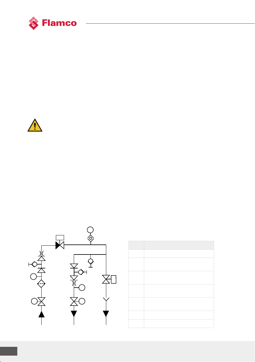
The following schematic shows the internal arrangement of the pressurisation unit:
1. Water enters the unit via the mains connection, isolation valve (IV) and through the back-flow
preventor.
2. Pressure sensors (P1 & P2) monitor the pressure in the mains water supply system and in the
heating or cooling system.
3. A solenoid inlet valve (S1) and a drain valve (S2) are activated when topping up is required.
4. The automatic air-vent (AAV) removes free air before it enters the sealed heating system.
5. Once the top up cycle is finished, the remaining water in the unit is removed by opening of the
drain valve (S2), to prevent legionella build up.
6. A filter on the mains supply to the unit is already installed. Where debris from the supply pipe is
expected, it is recommended to install an additional filter or Y-strainer on the mains water supply to
the unit.
Mains System Drain
AAV
IVIV
P1
P2
S
1
S
2
Icon Description
IV Isolation valve
P1 Pressure sensor to measure
mains water pressure
P2 Pressure sensor to measure
heating system pressure
S1 Valve to control mains water
inlet, normally closed (NC)
S2 Valve to control drain outlet,
normally open (NO)
AAV Automatic float air vent
Y Tundish

We reserve the right to change designs and technical specifications of our products.
11
ENG
6.2 Technical datasheet
WRAS approval number KUKreg4: 2202704
WRAS: 2203331
General
Size of the unit (Height x Width x Depth) 359mm x 225mm x 141mm
Dry weight 4 kg
Connection details
Cold water inlet 15mm Compression
System outlet 15mm Compression
Drain (via Tundish) 22mm Compression &
32mm PP push fit &
32mm PP solvent weld
Maximum inlet pressure 6 Bar
Maximum cold fill pressure 5.7 Bar
Maximum design pressure PN10
Nominal flow rate (at 2 Bar) 14l/min
Electrical details
Supply voltage 110/230 Volt
Frequency 50 Hz
Full load current 1 Amp
Fuse rating 5 Amp
Maximum load BMS relays 5 Amp
Protection class IP44
Environmental data
Power consumption (Standby) 2 W
Power consumption (Filling) 19,4 W
Operation conditions
Maximum temperature at inlet: 45°C
Maximum temperature at outlet: 90°C
Ambient temperature range: 5°C / 45°C
Storage conditions
Temperature 5°C / 45°C
Humidity 60….70% relative humidity, non-considering
Keep the unit in a locked, frost free and dry area, protect the unit from solar & thermal
radiation, vibration, from electrically conductive gases, explosive gas mixtures and
aggressive atmosphere.

Manual FlexFiller Direct G4
12
7 Installation requirements
The FlexFiller Direct G4 is a wall mounted unit and should be installed at a suitable eye level, where
the screen is easy to read and maintenance remains practical and possible. The wall of the set-up
location for the FlexFiller Direct G4 must be such that stability is guaranteed and maintained.
For general assembly instructions and commissioning steps of the product, see FlexFiller Direct G4
Quick Start Guide in link below:
https://flamcogroup.com/manuals/flexfiller-direct
All Flamco products should be installed by a Qualified Person with regard to the relevant
requirements described in section 5.4: ''Sta qualification''. Check that the installation and other
actions prior to use have been carried out in full (e.g. power supply available and connected,
functioning or active fuses, seal tightness of the equipment). Any damage or loss incurred through
incorrect commissioning by an unapproved engineer will not be covered by the warranty.
The following conditions must be met before starting the commissioning process. Failure
to meet these conditions may result in injury or damage to the equipment, system and/
or property.
Conditions
1. This equipment is designed to be installed in an indoor environment. The unit must be
installed in a frost free environment, away from precipitation and water sprays/jets.
2. The heating/cooling system is fitted with an appropriate safety valve and expansion
vessel.
3. Non-return valves, pressure reducing valves and RPZ valves must not be installed between
the pressurisation unit and the heating/cooling system. These devices will prevent the
pressure sensor from reading the system pressure.
4. It is essential to have the pressurisation unit and the associated system expansion vessel
connected to the system at the same point, to provide a neutral pressure reading. This
point of connection should be in the system return header, on the suction side of the
circulation pump.
5. All necessary pipe/electrical connections have been made to a local standard.
6. Refer to the appropriate datasheet for the maximum working pressure and temperature of
the pressurisation unit. The conditions at the point of connection to the system must not
exceed these values.
7. The expansion vessel is pre-charged to the correct pressure (equal toFlexFiller Direct G4
fill set-pressure))
It is advisable to fill the heating/cooling system prior to commissioning. If this is not
possible, the FlexFiller Direct G4 can be used to fill the system aer commissioning.
Depending on the size of the system, this may take a considerable amount of time.
A mains cable is provided with the unit. A mains cable length of 1,5 meter may not be
exceeded if replacement of a cable is necessary.
Two WRAS approved flexible hoses with isolation valves are provided with the unit. It is
essential for the maintenance of this unit to use hoses provided.

We reserve the right to change designs and technical specifications of our products.
13
ENG
7.1 Installation diagram
FlexFiller Direct G4
Pressurisation Unit
Mains
Cold Supply
To Drain
Isolation
Valves
Flexcon
Expansion Vessel
Isolation
Valve
Drain
Point
Isolation
Valves
Isolation
Valves
Boiler Boiler
Flow Return
3-Way
Valve
FlexBalance
Hydraulic Balancer
Isolation
Valves

Manual FlexFiller Direct G4
14
7.2 Clearance requirements
Clearance guidelines for service and repair.
120 mm
120 mm
35 mm 35 mm
800 mm
We reserve the right to change designs and technical specifications of our products.
15
ENG
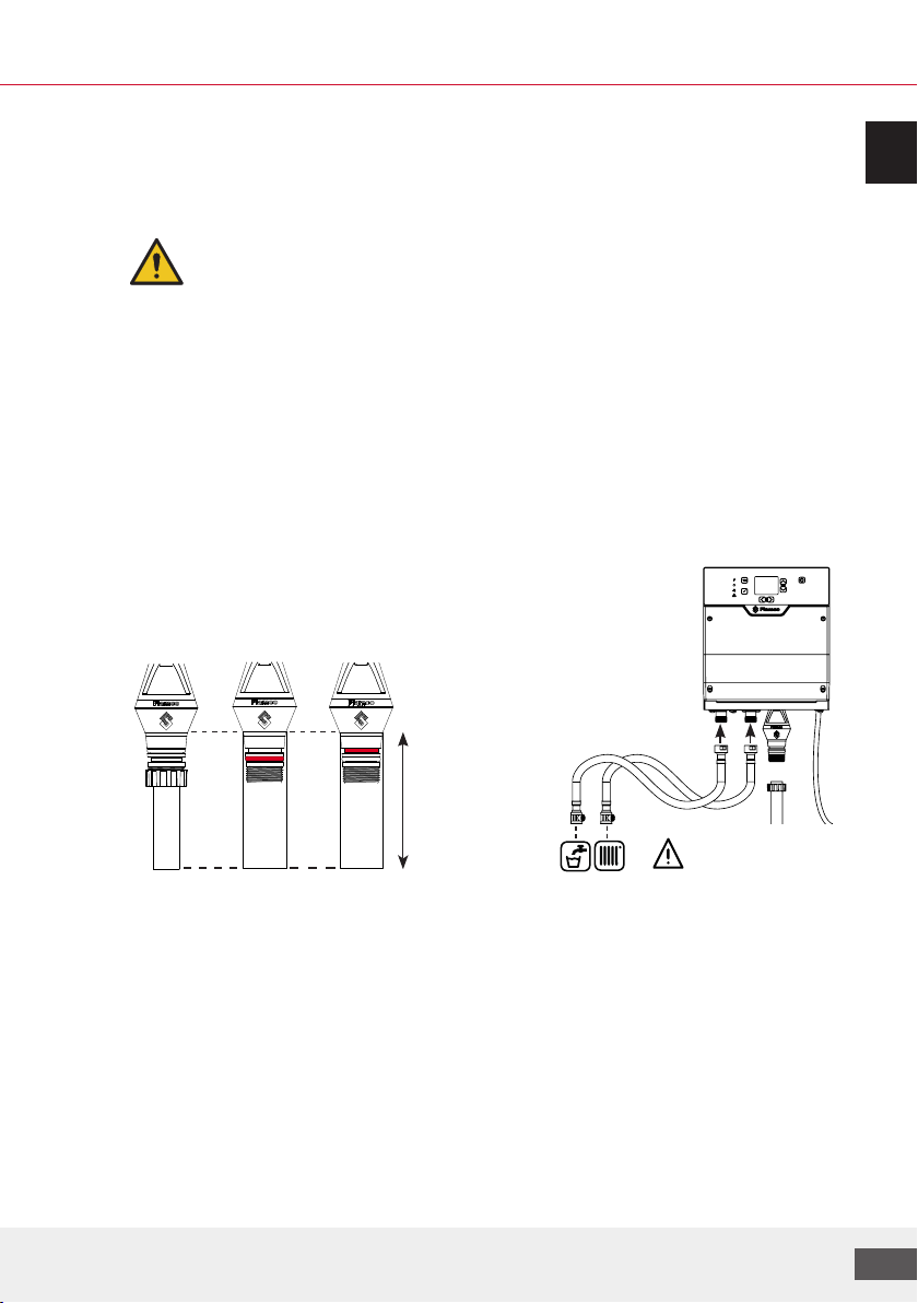
7.3 Hydraulic connections
From the “Manual-mode” in the controller menu, a testing routine can be triggered to check if the
device is set up correctly and working accordingly. Each actuator (valve) can be operated separately
with a maximum run-time of 2 minutes.
The mains water and sealed system connection to the unit must be made using the
flexible hoses with isolation valves provided.
The drain always has to be connected. There are 3 options to connect the drain:
• With a 22mm copper pipe
The plastic nut provided will secure the pipe in place and create a sealed connection
• With a 32mm push- fit PP pipe
The O-ring provided on the tundish will create a sealed connection with the pipe if positioned in
the lower groove on the tundish, see image below.
• With a 32mm solvent weld PP pipe
The O-ring provided on the tundish will create a sealed connection with the pipe if positioned in
the higher groove on the tundish, see image below.
Drain connection options
32 mm
push-fit
32 mm
solvent weld
Min drop dimension
120 mm
Always connect the drain-pipe
Abflussrohr immer anschließen!
Sluit altijd een afvoerleiding aan!
Raccordez toujours le tuyau d’évacuation!
22 mm copper
Connection

Manual FlexFiller Direct G4
16
7.4 Controller
A clarification of menu icons, function and location can be found in Appendix 1: Icon library.
G
K
H
L
A
E
F
B
C
D
123
I
J
P15
P15
P16 P17P18 P19 P20
CANRS485 P11
F1 F2 F3
5A
LN
PE
10A
10A
P21 P22 P23 P24 P25 P26
P27 P28 P29 P31
P30 P32 P33P34 P35 P36
123
P27 P28 P29P31
P30 P32 P33P34 P35 P36
Identification Description Pinout
A Power indicator (orange=power)
B Status indicator (green=ok automat running)
C Bluetooth Not Availible
D Error/alarm (red=alarm/error active)
E Confirm button
F Return button
G Navigation buttons
H Screen on/of (hold 8 sec for powerdown)
I Not Availible
J USB-A soware update + logging
CAN Not Availible
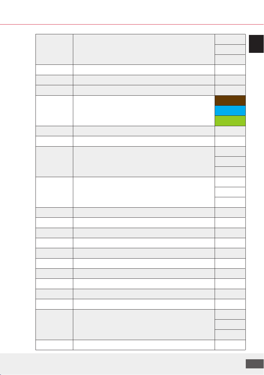
We reserve the right to change designs and technical specifications of our products.
17
ENG
RS485 Modbus/Bacnet/HFC over RS485 1 B+
2 B-
3 GND
F1 Fuse 1 (P31&P32) 5x20 5A
F2 Fuse 2 (P33&P35) 5x20 10AT
F3 Fuse 2 (P34&P36) 5x20 10AT
B Mains power connector 1 L
2 N
3 PE
L Mains grommet
P11 Not Availible
P15 SELV, System pressure 0-5V 1 +VDC
3 signal
3 GND
P16 SELV, Inlet pressure 0-5V 1 +VDC
3 signal
3 GND
P17 Not Availible
P18 Not Availible
P19 Not Availible
P20 Not Availible
P21 Not Availible
P22 Not Availible
P23 Not Availible
P24 Not Availible
P25 Not Availible
P26 Not Availible
P27 Fault contact, VFC 1 1 NO
2 COM
3 NC
P28 Not Availible

Manual FlexFiller Direct G4
18
P29 Not Availible
P30 Not Availible
P31 Power, V3 inlet solenoid valve 1 PE
2 L
3 N
P32 Not Availible
P33 Not Availible
P34 Not Availible
P35 Power, V1 Drain valve 1 PE
2 L
3 N
P36 Not Availible
7.5 Connectivity options
Connectivity options Designated use
Standard USB (USB-A) For saving the oline log and the configuration
parameters. The second option for this port
is to update the firmware of the controller (to
download a new control SW)
RS-485 The primary designation is to connect the
Flexfiller Direct G4 to internet (via Gateway and
HFC protocol).
Alternatively – BMS via Modbus
Alternatively – BMS via bacnet
(only one out of three options at the same time)

We reserve the right to change designs and technical specifications of our products.
19
ENG
8 Electrical installation
The provision of power supply, (protective) ground wire connection and line protection must be
made in accordance with the local regulations (responsible power company) and the applicable
National standards. The required electrical information can be found on the product label at the
side of the FlexFiller Direct G4, the terminal plan (labelling) and in “Appendix 3.” Terminal plan.
The FlexFiller Direct G4 has been supplied with the correct power supply cable and it is highly
recommended to use the cable provided.
All electrical connections should be carried out by a qualified and authorized electrician
in accordance with the latest issue of the IET regulations. The equipment must be
earthed. It is strongly recommended that a high sensitivity dierential switch (30mA)
(residual current device RCD) is fitted on the incoming electrical supply.
Do not remove covers without first ensuring that the electrical supply is suitably isolated
and cannot be switched on.
Do not attempt to supply electricity to the equipment unless the protective covers are
correctly fitted and held securely in place.
Cables connected to the controller volt free contacts may be supplied from another
source and may remain live aer the unit is isolated. These must be isolated elsewhere.
The user or the installer is responsible for the installation of the correct earthing and
protection according to valid national and local standards. All operations must be carried
out by a qualified electrician
The Flamco equipment must be connected to a mains isolator switch with a contact gap of at least 3
m. It is recommended the switch should be installed within 2m of the equipment.
8.1 Alarm installation
The installation, data processing and commissioning must be performed by a Qualified Person. The
appropriate national standards, regulations and rules must be followed.
• Additional cables are not included or supplied by Flamco
• Flamco recommends the use of twisted single pair shielded cable.
• The termination resistor has a value of 120 Ohm.
• The maximum permissible length of cables is 30m.
If controller powered down, than the is P27 normally open
If controller is powered up, than the is P27 normally closed
If controller is in error, than the is P27 normally open
For additional information on how to connect the the Flexfiller Direct to the internet or
BMS, see Flextronic connectivity guide.
P27
COM
NO NC
Building
management
system
BMS

Manual FlexFiller Direct G4
20
9 Operation
Once commissioned, the pressurisation unit should operate without any user intervention. Under
normal operating conditions, the display will show the current system pressure in Bar.
For an overview of the main operation screens, see image below.
A clarification of menu icons, function and location can be found in Appendix 1: Icon library
Home screen
While the unit is filling, the display will show the current status of the unit and its actuators (valves).
The system to which the unit is connected, is monitored and the icon in the top right corner signifies
its status.
Idle screen
When the unit is not active for a period of 30 seconds (standby), the display will show the total top up
amount in litres over a period of 28 days and the date of the next service.
Maintenance screen
Tapping the right arrow button “>” will show additional parameters like the set pressure, mains
pressure, legionella setting & duration and controller serial number.
Warning screen
Shows every active warning since the last time the warning screen has been cleared.
If the pressurisation unit is showing a fault code on the Home screen display, tapping the le arrow
button “<” will reveal the active fault message(s). The user can see an extended explanation of the
fault and by pressing the tick-button “✓” whilst on the selected fault.
To resolve the fault, simply click the tick-button “✓” again and the fault will be cleared.
To exit the extended explanation screen without resolving the fault, press the return- button " ".
When the fault condition is not resolved it will return on the display. Please use the troubleshooting
guide in Appendix 4 to resolve each fault accordingly.
2.22.2
23.5 L
28 days
05/07/2022
2.22.2
ON - 3 days
22345A13I2A
2.22.2
18 PRESSURE TO HIGH
2.22.2
117.2 L
Top up on
2.22.2
2.22.2
2.22.2
4:58
OR OR OR
17
2.22.2
CURRENT ALARMS (7)
18 Pressure to high (3)
2.1 bar
3.0 bar
Clear
117.2 L
Top up o
117.2 L
Drain open
.
Anti Legione
The system pressure is too
high. Top-up disabled until
issue resolved.
12-04-2022 14:30
Table of contents
Other flamco Industrial Equipment manuals


Popular Industrial Equipment manuals by other brands


Edwards
Edwards WRH gauge instruction manual

Roller
Roller Robot 2 instruction manual

TDW
TDW D2000 Maintenance Guidelines

Command access
Command access VLP-UL-M-KIT installation instructions

BobsCNC
BobsCNC Evolution Series Assembly manual

Generac Power Systems
Generac Power Systems PV Link 010023 installation manual