flamco Logotherm LogoComfort 500 User guide

ENG Installation and servicing instructions
www.flamcogroup.com/manuals
Logotherm
LogoComfort 500, 600 und 600+
as well as LogoComfort thermal heat exchangers BE 500, 600 and optional components

Manual for LogoComfort stations 24002.800
2
Abbreviations
LC LogoComfort
BE Thermal heat exchanger
CW Domestic water, cold
DHW / HW Domestic hot water
DWC/C Domestic water circulation
DW Domestic water
FL Heating flow line
RL Heating return line
UC/RH Unmixed heating circuit, static heating circuit for e.g. radiators
MC Mixed heating circuit
UFH/UFM Underfloor heating circuit / manifold
HC Heating circuit
PHE/HE Plate heat exchanger
CU Copper-soldered
ES Stainless steel-soldered
FT Female thread
MT Male thread
primary Primary heating circuit (heat supply)
sec. Secondary heating circuit (heat consumer)
HFM Energy meter
SM/FM Surface-mounted / flush-mounted
SMC/FMC Surface-mounted / flush-mounted cover
HE High-eiciency pump
BV Ball valve
WxHxD Width, height, depth

We reserve the right to change the designs and technical data of our products.
3
Table of Contents
Abbreviations .................................................................................................................... 2
1. Safety instructions...................................................................................................... 5
1.1 Intended use .............................................................................................................. 6
1.2 Device designations...............................................................................................................7
1.3 Hazard notes .........................................................................................................................7
1.4 What to do in the event of a breakdown or leaks....................................................................8
1.5 Spare and wear parts.............................................................................................................8
1.6 Requirements on trained engineers.......................................................................................9
1.7 Liability and copyrights.........................................................................................................9
1.8 Earth bonding or protective earthing in accordance with VDE................................................9
2. Functional description .............................................................................................. 10
3. LogoComfort stations................................................................................................ 11
3.1 LogoComfort 500/ 600 and 600+ as base stations.................................................................11
3.2 LogoComfort 500/600 and 600+ as prefabricated stations....................................................22
3.3 LogoComfort complete stations (CS)....................................................................................26
3.4 LogoComfort thermal heat exchanger (BE) 500/600 mm wide..............................................28
4. Installation............................................................................................................... 31
4.1 Installationnotesusingtheexampleoftheush-mountedcoverforLC500/600and600+ ..32
4.2 Mountingrailsandassemblyaidsforsurfaceandushmounting(optionalaccessories) ....33
4.3 DN20straight-wayballvalves(add-onelements) ................................................................35
4.4 Topconnections(add-onelement) ......................................................................................36
4.5 Installation of optional components (depending on variant) ...............................................36
5. Description of individual components and setting options .....................................................39
5.1 Hot water throttle (where included in the delivery range)....................................................39
5.2 Dirttrapwith/withoutllanddrainballvalve(dependingonvariant).................................40
5.3 Zone valve for heating circuit...............................................................................................41
5.4 Dierentialpressureregulator(dependingonvariant) ........................................................43
5.5 Thermostatic circulation bridge (depending on variant)......................................................44
5.6 Returntemperaturelimiter(add-onelement)......................................................................45
5.7 Thermostatichotwatermixingvalve(add-onelement........................................................45
5.8 Domesticwatercirculationsystem(LC600/600+add-onelement) ......................................47
5.10 Additional connection for static heating circuit
(LC600+,add-onelementMM28).................................................................................................63
5.11 Claddings / covers for LC stations (as optional accessories) .................................................64
5.12Congurationexamples ......................................................................................................69
6. Commissioning......................................................................................................... 71
6.1 Flushingandlling..............................................................................................................71
6.2 Initialstart-up .....................................................................................................................71
6.3 Seized Grundfos pumps, type UPM3 ....................................................................................72

Manual for LogoComfort stations 24002.800
4
7. Maintenance and service ........................................................................................... 74
7.1 Information regarding domestic water hardness .................................................................74
7.2 Maintenance checklist .........................................................................................................75
8. Troubleshooting and remedying possible faults........................................................... 77
9. Layout diagrams....................................................................................................... 77
10. Decommissioning, dismantling, disposal, environmental protection and disposal of
electrical andelectronic equipment .................................................................................. 79

We reserve the right to change the designs and technical data of our products.
5
1. Safety instructions
Please follow these safety instructions carefully to prevent
hazards and injury to persons and property.
These operating instructions are primarily designed for the safe use and installation of the device
and make no claims to completeness.
These operating instructions describe the functionality of the device and are intended to provide
information about the required safety instructions and to draw attention to possible hazards. Further
technical information can be found in the other applicable documents.
These operating instructions are valid only for the described device and are not subject to the
manufacturer’s revision service. The sketches and drawings they contain are not suitable to scale.
• Keep the operating instructions within easy reach of all employees instructed to carry out work
onthe device so that they can refer to them as required.
• Keep the operating instructions in a clean, complete and legible condition throughout the entire
period of use.
• Read the operating instructions before working on the device for the first time and consult them
whenever uncertainties or doubts arise as to how the device should be handled.
• Should you come across any discrepancies when reading these operating instructions or should
anything remain unclear, please contact the manufacturer.
Target group
These instructions are intended exclusively for authorised trained experts.
Only trained experts/installers authorised by the respective competence authority are permitted
towork on heating systems, domestic water, gas and electrical circuits.
Regulations
When carrying out work, you must comply with:
- The legal regulations concerning accident prevention and legal regulations regarding
environmental protection.
- The German Employer's Liability Insurance Association regulations,
- The pertinent safety requirements of DIN, EN, DVGW, TRGI, TRF and VDE,
- ÖNORM, EN, ÖVGW-TR Gas, ÖVGW-TRF and ÖVE,
- SEV, SUVA, SVGW, SVTI, SWKI and VKF
- and all current region- or country-specific regulations and standards
Instructions for working on the system
- Disconnect the system from the mains and monitor it to ensure that no voltage is being supplied
(e.g. at the separate cut-out or a main switch).
- Secure the system from restarting / switching to auxiliary power supply.
- WARNING! Risk of scalding at media temperatures: >60°C
Note: In the case of anticipated high primary temperatures of >60°C, thermostatic scalding
protection must be ensured at the domestic hot water draw-o point in order to restrict the outlet
temperature (in the event of a power failure).

Manual for LogoComfort stations 24002.800
6
Permissible mains supply and operating parameters
Heating side/primary side: Permissible pressure rating:
Max. permissible operating temperature:
Max. permissible dierential pressure:
- With actuator for zone valve:
PN10
110°C
2.0 bar
1.0 bar
Sanitation side: Permissible pressure rating:
Max. permissible operating temperature:
- In the case of an existing sanitary circulation
system:
(for short periods max. 70°C < 2 h)
Min. cold water pressure:
Recommended cold water operating pressure:
PN10
110°C
65°C
1.5 bar
2 bar
Max. permissible ambient
temperature: 40°C
• The devices must be installed in enclosed, frost-free spaces
• Any noise emissions or radiant heat from the station must be taken into account in the choice of
installation site
• Observe the safety areas in accordance with EN 60529 when designing and installing the system
(equipment protection code in accordance with EN 60520 IP42)
• Any domestic hot water (DHW) installation must be made safe in compliance with DIN 1988 or
DIN EN 806, for example, i.e. with the use of a safety valve and, where applicable, an expansion vessel.
1.1 Intended use
1.1.1 Proper use
Interface stations are used to transfer heat between the supply network and the heat consumer.
Interface stations may only be used for this purpose in compliance with the maintenance and
operating instructions and all relevant standards and regulations.
All instructions in the operating instructions must be followed and the maintenance schedule
adhered to.
Any deviation from the intended use may cause unintended hazards and is fundamentally
not permitted.
The LogoComfort heat interface station provides a residential unit with space heating and
domestichot water according to the continuous flow principle. Any additional or alternative use
isnot permitted and regarded as an unintended use.
Appropriate use in heating and domestic water systems must be in accordance with the applicable
DIN and local standards. Installing and operating the assembly incorrectly will invalidate any
warranty claims. The shut-o valves may only be closed by an approved specialist when servicing,
otherwise the safety valves will not work.
The LogoComfort heat interface station is not suitable for installation in adjacent recreation rooms
or bedrooms.
Care must be taken to avoid sound transmission to adjacent walls or rooms!
Caution:
Do not make any changes to the electrical components, the design of the equipment
or the hydraulic components! This would adversely impact on the safe function of
theequipment.

We reserve the right to change the designs and technical data of our products.
7
Instructions concerning the place of use:
Before using our products, they must be checked regarding their suitability for the respective
application.
In particular for heating systems, please take into account the properties of the heating water
inaccordance with VDI 2035 to protect the heating system and, for domestic water applications,
thewater quality at the place of use.
In the case of critical water qualities, please take action where necessary (e.g. water treatment)
toprevent functional impairment and/or damage, e.g. corrosion damage.
In particular, please check the permissible limit values, e.g. electrical conductivity, the pH value,
thewater hardness level and the ammonium concentration.
Furthermore, in Germany all applicable norms, regulations and guidelines specific to the federal
states must be taken into consideration, alongside the instructions in the applicable installation
andoperating manuals.
Further information can be found in the download section of www.flamcogroup.com.
1.1.2 Improper use
Using the device in any way that does not correspond to the intended use may be hazardous
andistherefore prohibited.
In particular, the following is not allowed:
• The use of liquids other than water with the described properties
• Use of the device without prior knowledge of the operating instructions
• Use of the device without legible warning and information signs
• Use of the device in a faulty condition
1.2 Device designations
Designation: Logotherm interface stations
Function: Transfer of thermal energy to the heating supply and hot water preparation
Type: LogoComfort
Manufacturer: Meibes System-Technik GmbH
1.3 Hazard notes
The safety and warning information draws attention to residual hazards that cannot
be avoided due to the design and construction of the device. Please always observe
the measures shown for avoiding these hazards
Never alter or modify the station yourself. Such work may only be carried out by qualied,
specialist personnel. This also applies to the electrical installation.
When the system is in operation, water-regulating components will be hot. Touching these system
components can lead to scalding. The interface station and its heat-carrying components must
be operated with permanent insulation. This insulation not only prevents unnecessary thermal
dissipation, but also protects against accidental contact and burns. The insulation must therefore only
be removed for maintenance or repair purposes and replaced correctly on completion of such work.
The system is operated using hot, high-pressure water, which can cause scalding on contact.
You should therefore open the bleed or drain valves carefully and not work on pressurised parts.
The control components (controller, servomotors, pumps, etc.) are powered by mains voltage.

Manual for LogoComfort stations 24002.800
8
Therefore, always ensure the station is disconnected from the mains electrical supply when
carrying out any maintenance or repair work. Secure the system against unauthorised operation.
Life-threatening electric shocks can be caused by spraying or splashing water. Escaping water may
also disable the safety devices.
Any changes made to the station that have not been authorised by the manufacturer will invalidate
any warranty claims.
Residual hazards:
The product has been built in accordance with the most relevant and recognised safety regulations.
The following residual hazards may arise during installation, commissioning, maintenance and
disassembly:
Warning: Risk of scalding from high media temperature
- Work with particular caution.
- Use personal protective equipment PPE (e.g. heat-resistant protective gloves).
- If necessary, the surface temperature must be measured before commencing any work.
- Use only designated and appropriate tools.
Hazard: Risk of injury from electrical voltage
- Only trained and qualified electricians may undertake work on electrical equipment.
- Electrical installation spaces must always be kept locked.
Warning: Risk of cuts and scratches due to the possibility of sharp edges
- Work with particular caution.
- Use personal protective equipment PPE (e.g. protective gloves).
Warning: there is a risk of impact/crushing if the station falls over
- Wear personal protective equipment PPE (such as protective work shoes).
1.4 What to do in the event of a breakdown or leaks
• Close any media lines using the appropriate valve.
• Contact a suitably trained expert or the customer service department of the manufacturer.
The device will only be cleared for operation again when the trained engineer has remedied
the fault and restored the device to its intended condition.
1.5 Spare and wear parts
All spare parts to be used, must correspond to the technical requirements defined by Meibes
System-Technik GmbH. This is guaranteed only by using genuine spare parts. The manufacturer
isnot liable for damage caused by the use of unapproved spare parts or ancillary materials.
Appropriate spare parts can be found in our documentation.

We reserve the right to change the designs and technical data of our products.
9
1.6 Requirements on trained engineers
A qualified professional must have undergone advanced technical training and have suicient
experience to independently perform complicated tasks or work associated with residual hazards.
Each experience refers to a certain speciality, e.g. Maintenance, Electrical and/or HVAC Technician
In preparation for impending work, a qualified professional must be able to correctly estimate the
feasibility, risks and hazards of the work as well as the equipment required. A qualified professional
is expected to understand complex plans and descriptions of minimum preparation, and to obtain
missing and required detailed information by suitable means.
The qualified professional must be able to restore and verify the intended/original state of the
system. A worker can be a trained expert in several fields. For the performance of electrical works,
only trained electricians according to DGUV regulation 3 may be used.
1.7 Liability and copyrights
We reserve all copyrights to this document. Any misuse, in particular reproduction or disclosure
tothird parties, is prohibited.
This original operating manual may not be reproduced or distributed, either in part or in its entirety,
without the express permission of the manufacturer. This also applies to translations of this document
and storage on other media. This document must not be used outside its intended purpose.
These installation and operating instructions must be given to the customer. The technician carrying
out and/or authorising the work (e.g. installer) must explain the function and operation of the system
to the customer in a comprehensible way.
1.8 Earth bonding or protective earthing in accordance with VDE
A terminal for earth bonding is provided
on all heat interface stations. An
appropriately labelled earth stud can be
found on the base plate for this purpose
The cable's connection cross-section must
bedesigned according to the applicable standards
andregulations.

Manual for LogoComfort stations 24002.800
10
2. Functional description
The LogoComfort (LC) interface stations provide a residential unit with domestic hot water and
heating. The domestic water is heated according to the continuous flow principle by a plate heat
exchanger and a pressure-controlled proportional flow controller (PF controller with 3- way function)
with anti-scale coating and DVGW
(German Association for Gas and Water)
approval.
Operation:
The PF controller with 3- way function
only opens the domestic water and
heating water media flows via the plate
heat exchanger when the hot water is
being drawn o. Once the water has
been drawn o, the valve closes and
thus prevents the continued heating
of the heat exchanger. The dwelling
heating circuit is shut o while the
hot water is being drawn o (priority
switching).
The entire thermal energy is thus
available for the hot water preparation.
Notes:
If a constant heating supply
temperature is ensured, the same
hot water temperature is always
achieved by means of proportional
flow regulation when small or large
quantities are drawn o.
The use of a thermal mixing valve*
ensures scalding protection with very high or erratic heating medium temperatures and anticipated
hot water temperatures of > 60°C.
We recommend using a thermostatic circulation bridge* at the end of the supply line or in the last
station in order to guarantee the thermal stability and/or avoid waiting times until the desired hot
water temperature is achieved.
If the connecting pipework between the supply line and the station is very long, it is worth installing
a thermostatic circulation bridge* in every station. The dierential pressure regulator* upstream
of the station provides a stable pressure dierential for the hot water preparation. Alternatively, it
is possible to install the dierential pressure regulator or another suitable fitting in the supply line
(heating).
A zone valve permits hydraulic balancing of the dwelling heating circuit.
Installing a living space or reference room controller* allows independent operation of the dwelling
heating circuit.
Any adapters* (L =110 mm, 2 x ¾" MT) for optional water meters and heat meters allow retrofitting in
the stations
* Corresponding station components may be available or present as optional accessories or as add-on
elements.

We reserve the right to change the designs and technical data of our products.
11
3. LogoComfort stations
The following sections describe the station variations as well as possible optional models
withexample illustrations.
3.1 LogoComfort 500/ 600 and 600+ as base stations
LogoComfort base station as a local interface station:
- for customisation
- incl. PF controller with priority switching, incl. adapters for optional heat meter
- Connection pipework made of insulated stainless steel corrugated tube, fully mounted on base
plate and tested
The following base stations can be equipped with various add-on elements (see module
summary, Section 3.1.4). These are installed in the factory and delivered as a prefabricated
station. Corresponding surface-mounted / flush-mounted covers, as well as room controllers
andaccessories, are also available.
3.1.1 Technical data
LogoComfort base station variations with art. No.
Output** LC 500 base LC 600 base LC 600+ base
35 kW S-Line M11401 M11301 M11304
46 kW M-Line M11303 M11306
Dimensions of WxHxD in mm
(where depths depend on the optional accessories)
LC 500 base: 480 x 635 x 175
LC 600 base: 576 x 635 x 175
LC 600+ base: 480 x 657 x 175
Heating capacity 10 kW (at 20 K)
Hot water output** 35 kW (at 40 K), 12 l/min
46 kW (at 40 K), 17 l/min
** Where FL=65°C and DW heating by 40 K

Manual for LogoComfort stations 24002.800
12
LogoComfort 500/ 600 base
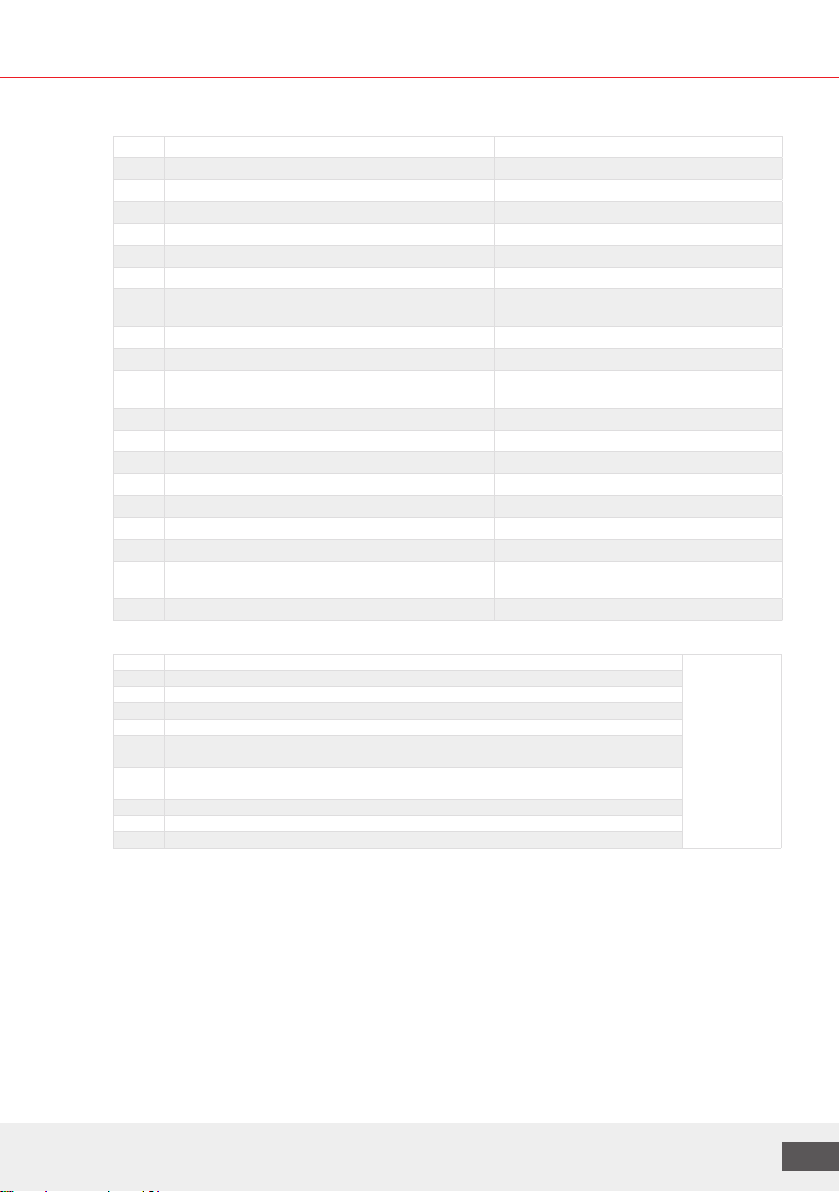
3.1.2 Design and components
Components and connections Hydraulic diagrams
Fig.: Example representations
Shown with possible add-on elements
Fig.: Example representations
Shown with possible add-on elements
LogoComfort 600+ base
We reserve the right to change the designs and technical data of our products.
13
Key for LogoComfort base stations
No. Components Comment
1Stainless steel plate heat exchanger
2a Adapter for cold water meter (L = 110 mm, 2 x ¾" MT) Option
2b Adapter for heat meter (L = 110 mm, 2 x ¾" MT)
3Stainless steel corrugated tube pipework, insulated
4a Dirt trap with flushing, filling and drain ball valve Option
5Dierential pressure regulator, control range 10-40kPa Option
6PF controller with 3- way function with priority switching, anti-calcification
coating and DVGW approval
72nd CW connection Option
8Thermostatic circulation bridge 35 ... 65°C Option
9Zone valve (optional: living space controller),
for 1st HC included delivery range
Control valve for heating water (dwelling)/
zone valve
13 Hot water throttle 12 or 17 l/min
14 Automatic air vent Bleed valve on the heating side
15 Thermostatic hot water mixer (scald protection) Option
17 Return line temperature limiter 45… 65°C Option
18 ½" coupler for heat meter immersion sleeve Option, if Item 20 present
19.1 Domestic water circulation group, only for 600/600+ Option
19.2 Circulation bridge 35 ... 65°C, only for 600/600+ Option, if Item 19.1 present
20 DN20 shut-o valve, union nut x ¾" FT domestic water
ball valve DVGW approved, FL ball valve with HFM sensor
Option
21 Corresponding mixing circuit with HE pump Depending on the variant
Connections
ACold water outlet for dwelling, (second CW connection) - Option G ¾" MT
(without ball
valves)
BDomestic hot water outlet for dwelling (HW)
CCold water inlet building connection (CW)
DHeating – flow line building connection (FL heating)
EHeating – return line building connection (RL heating)
FHeating – flow line dwelling heating circuit 1 (unmixed or mixed HC) -
depending on the variant
GHeating – return line dwelling heating circuit 1 (unmixed or mixed HC) -
depending on the variant
HHeating – flow line dwelling heating circuit 2 (unmixed HC) - option
IHeating – return line dwelling heating circuit 2 (unmixed HC) - option
JDomestic water circulation - option
Note: for optional components, see Section 3.1.4

Manual for LogoComfort stations 24002.800
14
3.1.3 Dimensions of connections and base plate with keyholes
Note: Dimensions relate to stations without housing or covers!
Dimensions in [mm]
a=480 (576)
b=620
c=110
d=65
e=24.5 (72.5)
f=50
g=462 (558)
h=450
i=68
Warning!
For 600 series stations,
dimensions are given
in brackets (xxx)
Fig.: Example representations
Dimensions in [mm]
a=576
b=620
c=110
d=65
e=58.8
f=50
g=558
h=450
i=68
LogoComfort 500/600 baseLogoComfort 600+ base
We reserve the right to change the designs and technical data of our products.
15
3.1.4 Add-on elements LogoComfort 500/600 and 600+ as base stations
The following add-on elements (modules) may be present. These are installed at the factory.
Thepossible combination options are also included in the current price list.
3.1.4.1 Summary of add-on elements and LC equipment options
Module for LC base stations
500 600 600+ Components Fig. Modules
(example representations)
See section
MM1 - 2x dirt traps with drainage
Note:
For LC 600 base variants
with side connection sets
as a mixing circuit or for
the LC 600+, only 1 x dirt
trap ispossible in each case
(seeMM26 module)
5.2
MM2 Cold water connection (CW)
with CW meter connection
piece
4.5.2
Art. No.: M10253.8 2nd water meter adapter
(2nd WM) for stations with
MM2 module
Art. No.: M10253.7 2nd water meter adapter
(2nd WM) for stations without
MM2 module
MM4 Adjustable circulation bridge
35-65°C
5.5
Manual for LogoComfort stations 24002.800
16
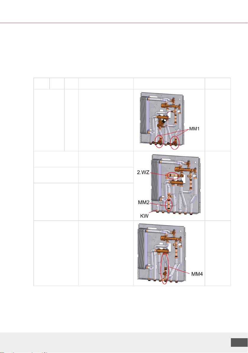
MM5 Dierential pressure regulator
with control range 10-40kPa
5.4
MM6 Scalding protection:
thermostatic hot water mixer
valve, adjustable: 35-60°C
5.7
Module for LC base stations
500 600 600+ Components Fig. Modules
(example representations)
See
section
- MM8
(Art No.:
M10252.12)
Domestic water circulation
with:
- Pump incl. automatic
timer
- Backflow preventer
- Adjustable circulation
bridge 35-65°C
5.8
MM9 - Top connection with:
7 x connection lines,
frame depth 50 mm
4.4

We reserve the right to change the designs and technical data of our products.
17
MM11 Return line temperature
limiter 35-65°C
5.6
MM23
(Art No.:
M10252.32)
- Straight-way ball valve
set with:
7x DN20 BV, flow line
ball valve for HFM sensor
mounting
Note:
Domestic water ball valve
DVGW-approved
4.3
MM19
(Art No.:
M10252.34)
Straight-way ball valve set
with:
5x DN20 BV, flow line
ball valve for HFM sensor
mounting
Note:
Domestic water ball valve
DVGW-approved
- MM26 1x dirt trap with drainage
Note:
for LC 600 base variants
with side connection set
as a mixing circuit or for
LC 600+
5.2
Manual for LogoComfort stations 24002.800
18
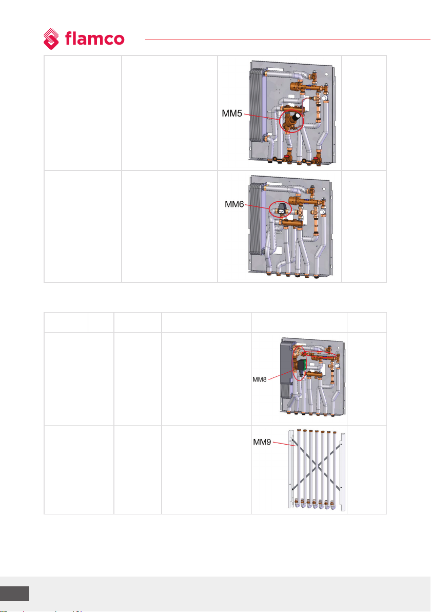
MM28 Additional connection
forstatic heating circuit
Note:
only up to manifolds for
5HC, from the 6th HC
onlyin combination with
600 base
5.9.4.2.
- - MM12HE Compact mixing circuit
group with servomotor
andHE pump for UFH
manifold 3-8 HC (type B).
5.9
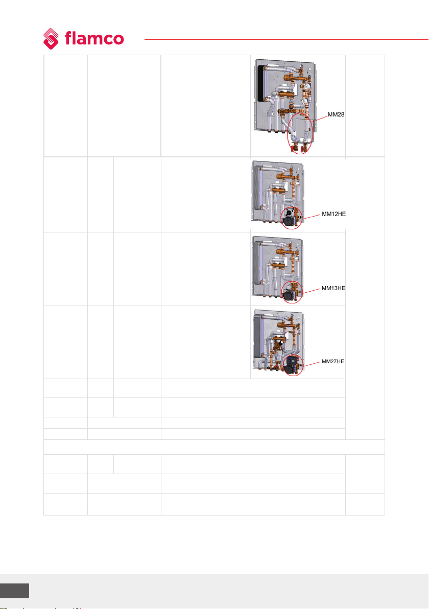
- - MM13HE Compact mixing circuit
group with thermostatically
controlled mixing circuit
and HE pump for UFH
manifold 3-8 HC (type B)
- - MM27HE Compact mixing circuit
group with controlled
servomotor, flow line
temperature sensor and
HE pump for UFH manifold
3-8 HC (type B)
- √ - Corresponding side connection sets as a mixing circuit with
HE pump for optional manifold 3-12 HC (type E)
- Type E Type B Underfloor heating circuit manifold, type B: 3-8 or type E:
3-12 HC
MB-10560.09 Pre-wiring concept for use with up to 8 zones*
MB-10560.10 Pre-wiring concept for use with up to 10 zones*
* Up to 18 actuators can be connected and therefore multiples in each zone
MM10230.5SC - MM10230.5SC Heat exchanger for domestic water with high conductivity
for 12 l/min
- MM10232.58ES Heat exchanger for domestic water with high conductivity
for 17 l/min
- M10230.51 Insulated HE for 12 l/min
- M10232.592 Insulated HE for 17 l/min
We reserve the right to change the designs and technical data of our products.
19
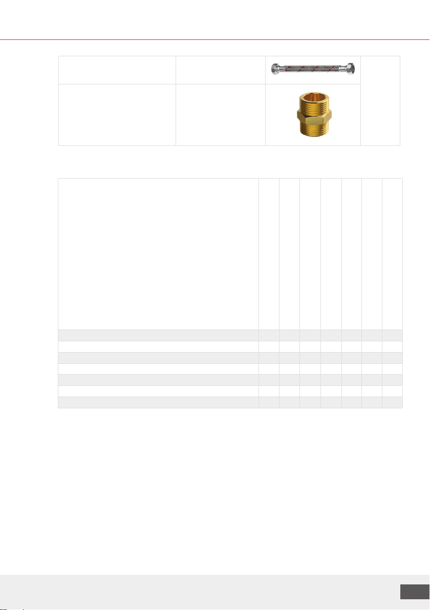
M4325.1227.50 Meiflex SST flushing hose
¾" FT x FT, 500 mm long
4.2.2
M43.66124D Flushing connections
10x DN16 double nipples
(¾" flat-sealing)
3.1.4.2 Combination options of the add-on elements for LC 500/600 and 600+
LC 500 base stations
Combination options of the individual add-on elements (modules)
Dirt trap with drainage MM1 o o o o o o o
Cold water connection MM2 o o o o o o
Circulation bridge MM4 o o o o o
Dierential pressure regulator MM5 o o o o
Scalding protection MM6 o o o
Connector set top MM9 o o
Return line temperature limiter MM11 o
Key: o = possible
MM2 Cold water connection
MM4 Circulation bridge
MM5 Dierential pressure regulator
MM6 Scalding protection
MM9 Top connector set
MM11 Return line temperature limiter
MM23 Straight-way ball valve set DN20

Manual for LogoComfort stations 24002.800
20
LC 600 base stations
Combination options of the individual add-on
elements (modules)
Dirt trap with drainage MM1 o o o o o o o o o
Cold water connection MM2 o o o o o o o o
Circulation bridge MM4 o o x o o o o
Dierential pressure regulator MM5 o o o o o o
Scalding protection MM6 o o o o o
Domestic water circ. with pump MM8 x o o o
Connector set top MM9 o x o
Return line temperature limiter MM11 o o
Heating circuit manifold o
Key: o = possible, x = not possible
Note on the LC 600 base:
Manifold installed on base plate for possible connection sets with heating circuit pump: see Section 5.9.2
MM2 Cold water connection
MM4 Circulation bridge
MM5 Dierential pressure regulator
MM6 Scalding protection
MM9 Top connector set
Heating circuit manifold
MM8 domestic water circulation
with pump
MM11 Return line temperature limiter
MM23 Straight-way ball valve set DN20
This manual suits for next models
1
Table of contents
Other flamco Industrial Equipment manuals


