SICK VISIC100SF User manual

MMM
I
MMMOPERATING INSTRUCTIONS
OPERATING INSTRUCTIONS
VISIC100SF
Gas Adjustment Kit
Title Page

28027092/AE00/V1-0/2022-10 | SICKOPERATING INSTRUCTIONS | VISIC100SF
Subject to change without notice
Described product
Product name: VISIC100SF Gas Adjustment Kit
Manufacturer
SICK AG
Erwin-Sick-Str. 1
79183 Waldkirch
Germany
Legal information
This work is protected by copyright. All rights derived from the copyright shall be reserved
for SICK AG. Reproduction of this document or parts of this document is only permissible
within the limits of the legal determination of Copyright Law.
Any modification, shortening or translation of this document is prohibited without the
express written permission of SICK AG.
The trademarks stated in this document are the property of their respective owner.
© SICK AG. All rights reserved.
Original document
This document is an original document of SICK AG.

CONTENTS
3
8027092/AE00/V1-0/2022-10 | SICK O P E R A T I N G I N S T R U C T I O N S | VISIC100SF
Subject to change without notice
1 About this document................................................................................. 5
1.1 Function of this document.............................................................................. 5
1.2 Scope of application ....................................................................................... 5
1.3 Target groups .................................................................................................. 5
1.4 Further detailed information .......................................................................... 5
1.5 Symbols and document conventions ............................................................. 5
1.5.1 Warning symbols ............................................................................5
1.5.2 Warning levels and signal words.................................................... 5
1.5.3 Information symbols ....................................................................... 6
1.6 Data integrity ................................................................................................... 6
2 For your safety............................................................................................ 7
2.1 Basic safety information ................................................................................. 7
2.1.1 Electrical safety............................................................................... 7
2.1.2 Dangerous substances................................................................... 8
2.2 Intended use ...................................................................................................8
2.3 Requirements for personnel qualification ..................................................... 8
3 Product description ................................................................................... 9
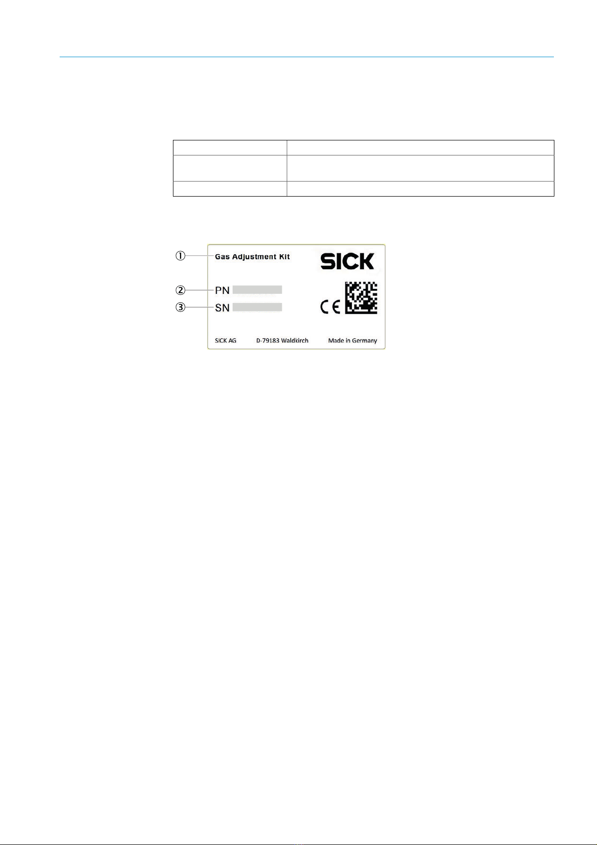
3.1 Product identification...................................................................................... 9
3.2 Layout and function ......................................................................................10
3.2.1 Gas Adjustment Kit.......................................................................10
4 Transport and storage.............................................................................11
4.1 Transport, VISIC100SF Gas Adjustment Kit.................................................11
4.2 Storage, VISIC100SF Gas Adjustment Kit and accessories........................11
4.3 Transporting and storing test gases.............................................................11
4.3.1 Regulations applicable for VISC100SF........................................11
4.3.2 Securing loads ..............................................................................11
4.3.3 Valve protection ............................................................................11
4.3.4 No smoking allowed .....................................................................11
4.3.5 Hazard labels ................................................................................11
4.3.6 Ventilation .....................................................................................11
4.3.7 Transport document .....................................................................12
4.3.8 Vehicle equipment ........................................................................12
4.3.9 Other equipment...........................................................................12
4.3.10 Marking .........................................................................................12
4.3.11 Accident leaflet .............................................................................12
4.3.12 Training .........................................................................................12
4.3.13 Disposal.........................................................................................12
5 Operation ..................................................................................................13
5.1 Operating concept.........................................................................................13
Contents
Contents

CONTENTS
48027092/AE00/V1-0/2022-10 | SICKO P E R A T I N G I N S T R U C T I O N S | VISIC100SF
Subject to change without notice
5.2 Displays and operating elements ................................................................ 13
5.2.1 Adjustment tool ............................................................................ 13
5.2.2 Status LEDs .................................................................................. 13
5.2.3 Keypad .......................................................................................... 14
5.3 Navigating and setting.................................................................................. 14
5.4 Status and malfunction messages .............................................................. 14
5.5 Measuring point............................................................................................ 14
6 Menus........................................................................................................ 15
6.1 Start menu .................................................................................................... 15
6.2 Menu tree...................................................................................................... 15
6.3 Menu - Nom./Gas/Unit................................................................................. 15
6.4 Menu - Error status....................................................................................... 16
6.5 Menu - Measuring Values............................................................................. 16
6.6 Menu - Display Parameters .......................................................................... 16
6.7 Menu - Installation and Calibration ............................................................. 17
6.7.1 MP Parameters............................................................................. 17
6.7.2 System Parameters ...................................................................... 17
6.7.3 Menu - Operating Data................................................................. 18
6.7.4 Menu - Calibration ........................................................................ 19
6.7.4.1 Adjust zero point....................................................... 19
6.7.4.2 Adjust sensitivity ....................................................... 20
7 Adjustment ............................................................................................... 21
7.1 Safety ............................................................................................................ 21
7.2 Materials and tools required........................................................................ 21
7.3 Preparation ................................................................................................... 22
7.4 Perform adjustment...................................................................................... 23
7.4.1 Sequence and duration................................................................ 23
7.4.2 Connections between gas sensor and test gas cylinder ............ 23
7.4.3 Select gas type ............................................................................. 24
7.4.4 Performing zero point adjustment............................................... 25
7.4.5 Performing sensitivity adjustment ............................................... 26
7.4.6 Final steps .................................................................................... 27
8 Technical data.......................................................................................... 28
8.1 Test gases ..................................................................................................... 28

5
8027092/AE00/V1-0/2022-10| SICK OPERATING INSTRUCTIONS |VISIC100SF
Subject to change without notice
ABOUT THIS DOCUMENT 1
1Aboutthisdocument
1.1 Function of this document
This document describes:
●Adjusting the gas sensors
●Transport and storage conditions for the VISIC100SF Gas Adjustment Kit
●Important safety information for safe operation.
1.2 Scope of application
These Operating Instructions apply exclusively to the VISIC100SF Gas Adjustment Kit from
SICK for adjusting the CO, NO and NO2gas sensors used in the VISIC100SF.
They are not applicable for other SICK devices.
1.3 Target groups
This Manual is intended for persons qualified to perform an adjustment of the VISIC100SF
gas sensors.
1.4 Further detailed information
●VISIC100SF Operating Instructions
1.5 Symbols and document conventions
1.5.1 Warning symbols
1.5.2 Warning levels and signal words
DANGER:
Risk or hazardous situation which will result in severe personal injury or death
WARNING:
Risk or hazardous situation which could result in severe personal injury or death
Symbol Significance
Hazard (general)
Hazard through voltage
Hazard through acidic substances
Hazard through toxic substances
Hazard through noxious substances
Hazard for the environment/nature/organic life

68027092/AE00/V1-0/2022-10| SICKO P E R A T I N G I N S T R U C T I O N S | VISIC100SF
Subject to change without notice
1ABOUT THIS DOCUMENT
CAUTION:
Hazard or unsafe practice which could result in less severe or minor injuries
NOTICE:
Hazard which could result in property damage
Note:
Tips
1.5.3 Information symbols
1.6 Data integrity
SICK AG uses standardized data interfaces, such as standard IP technology, in its products.
The focus here is on product availability and features.
SICK AG always assumes the integrity and confidentiality of data and rights affected in
connection with the use of the products are ensured by the customer.
In all cases, the customer is responsible for the implementation of safety measures
suitable for the respective situation, e.g., network separation, firewalls, virus protection and
patch management.
Symbol Significance
Important technical information for this product
Important information on electric or electronic functions

7
8027092/AE00/V1-0/2022-10| SICK OPERATING INSTRUCTIONS |VISIC100SF
Subject to change without notice
FOR YOUR SAFETY 2
2Foryoursafety
2.1 Basic safety information
▸Read and observe these Operating Instructions.
▸Observe all safety information.
Correct use
▸Only use the measuring device as described in “Intended use”. The manufacturer
assumes no responsibility for any other use.
▸Maintenance work should be performed as prescribed in this Manual.
▸Do not perform any work or repairs on the measuring device not described in this
Manual.
▸Do not remove, add or modify any components to or on the device unless described and
specified in the official manufacturer information.
▸Use only original spare parts and wear and tear parts from SICK.
Failure to observe these precautions could result in:
●Voiding the manufacturer's warranty.
●Causing the device to become dangerous.
Special local conditions
In addition to the information in these Operating Instructions, follow all local laws, technical
rules and company-internal operating and installation directives applicable wherever the
device is installed.
Retention of documents
These Operating Instructions:
▸Must be available for reference.
▸Must be conveyed to new owners.
Ensure the operational safety during all work on the device
The VISIC100SF is mainly used in combination with regulation and control technology.
▸During all work on the device, ensure that this can not lead to hazards or hindrances for
traffic.
2.1.1 Electrical safety
Hazard through electrical shock
There is a risk of electric shock when working on the measuring device with the voltage
supply switched on.
●Before starting work on the measuring device, ensure the power supply can be switched
off using a power isolating switch or circuit breaker in accordance with the valid
standard.
●Switch off the power supply before carrying out any work on the measuring device.
●After completion of the work or for test purposes or adjustment, the power supply may
only be activated again by authorized personnel complying with the safety regulations.

88027092/AE00/V1-0/2022-10| SICKO P E R A T I N G I N S T R U C T I O N S | VISIC100SF
Subject to change without notice
2FOR YOUR SAFETY
2.1.2 Dangerous substances
Hazard through acidic liquids
If the gas sensor is mechanically damaged, corrosive liquid may escape and cause serious
injury.
●Take appropriate protective measures for work (e.g., by wearing a safety mask,
protective gloves and acid resistant clothes).
●In case of contact with the skin or eyes, rinse the affected parts immediately with clear
water and consult a doctor.
Hazard through escaping calibration gases
Incorrect handling of calibration gases can cause high concentrations above the workplace
exposure limits to escape from the gas sensor into the ambient air and lead to poisoning.
●Observe the Safety Datasheets of the calibration gases.
●Ensure adequate ventilation.
●Limit gassing time.
2.2 Intended use
The Gas Adjustment Kit serves to check and adjust the gas sensors in the VISIC100SF.
2.3 Requirements for personnel qualification
The device may only be operated by authorized persons who, based on their training on,
and knowledge of the specific device, as well as knowledge of the relevant regulations can
assess the tasks given and recognize the hazards involved.

9
8027092/AE00/V1-0/2022-10| SICK OPERATING INSTRUCTIONS |VISIC100SF
Subject to change without notice
PRODUCT DESCRIPTION 3
3 Product description
3.1 Product identification
Fig. 1: Type plate, Gas Adjustment Kit
Product name VISIC100SF Gas Adjustment Kit
Manufacturer SICK AG
Erwin-Sick-Str. 1 · 79183 Waldkirch · Germany
Type plate On the lid of the case, right bottom
Designation
Part number
Serial number

10 8027092/AE00/V1-0/2022-10| SICKO P E R A T I N G I N S T R U C T I O N S | VISIC100SF
Subject to change without notice
3PRODUCT DESCRIPTION
3.2 Layout and function
The Gas Adjustment Kit continuously checks the gas type and measuring range set for
agreement with gas type and measuring range of the connected gas sensor and outputs an
error if there is an inconsistency.
3.2.1 Gas Adjustment Kit
Fig. 2: Contents, Gas Adjustment Kit
Designation
1Hose (marked blue/orange),
3 m for nitrogen monoxide (NO) and nitrogen dioxide (NO2)
2Hose, transparent (marked pink),
3 m for carbon monoxide (CO) and synthetic air
3Accessories: 2 × hose adapters and transition pieces,
2 × replacement seals (O-rings) for tapping valves
4 Stainless steel sampling valve (marked blue) for NO and NO2, flow rate: 0.5 l/min
5 Brass sampling valve (marked pink) for CO and synthetic air, flow rate: 0.5 l/min
6 Adjustment tool
Operating Instructions
Note:
It is assumed that the test gases are provided by the customer.
Calibration gas data, see “Test gases”, page 28.

11
8027092/AE00/V1-0/2022-10| SICK OPERATING INSTRUCTIONS |VISIC100SF
Subject to change without notice
TRANSPORT AND STORAGE 4
4 Transport and storage
4.1 Transport, VISIC100SF Gas Adjustment Kit
No special regulations must be observed when transporting and storing the Gas
Adjustment Kit. The standard SICK AG regulations are applicable.
4.2 Storage, VISIC100SF Gas Adjustment Kit and accessories
Always store the contents of the Service case in the Service case.
4.3 Transporting and storing test gases
The following Sections describe the general obligations when transporting and storing test
gases or test gas cylinder for the VISIC100SF Gas Adjustment Kit.
4.3.1 Regulations applicable for VISC100SF
●The dangerous goods amount in the vehicle must NOT exceed 1000 ADR (Accord
européen relatif au transport international des merchandises dangereuses par route)
points.
●The test gases or test gas cylinders may only be transported to the place of use to carry
out measurements, repairs or maintenance work, i.e. no supply trips!
●Also observe the respective local regulations!
4.3.2 Securing loads
The load must always be secured adequately, also during transport in private vehicles.
●Lashing straps
●Clamping bars
●Wedges etc.
Secure the load so that pieces being transported cannot change direction and therefore
not damage the load. The test gases or test gas cylinders may only be transported in the
intended bags.
4.3.3 Valve protection
The closing valves must be protected against damage (e.g. by protective caps, valve
protection collars, protective boxes, etc.).
4.3.4 No smoking allowed
Open fire or light is forbidden during loading work, in the proximity of the transport pieces
and other vehicles as well as in the vehicles.
4.3.5 Hazard labels
Hazard labels must be affixed to the test gas cylinders. The code is required in the bottom
corner of the hazard label.
4.3.6 Ventilation
No special ventilation is required when the limit values (see 4.3.1) are observed.

12 8027092/AE00/V1-0/2022-10| SICKO P E R A T I N G I N S T R U C T I O N S | VISIC100SF
Subject to change without notice
4TRANSPORT AND STORAGE
4.3.7 Transport document
4.3.8 Vehicle equipment
Not required when carrying a maximum of 340 liters of specified CO test gas cylinders or
880 liters of specified NO test gas cylinders or 4290 liters of specified NO2test gas
cylinders.
4.3.9 Other equipment
Not required.
4.3.10 Marking
Not required.
4.3.11 Accident leaflet
Not required.
4.3.12 Training
All persons involved in transporting dangerous goods (e.g. driver, loader, consignor,
consignee, filler, transporter) must have received appropriate training.
4.3.13 Disposal
Test gas cylinders that are not emptied must be returned to the supplier and the supplier is
responsible for their disposal.
Note:
▸Always carry the transport document.
The transport document is not required in Germany in compliance with Exception 18
GGAV when:
●Gases are not transferred to third parties
●No special agreement is applied
●A proof of quantity (e.g. delivery bill) is available

13
8027092/AE00/V1-0/2022-10| SICK OPERATING INSTRUCTIONS |VISIC100SF
Subject to change without notice
OPERATION 5
5Operation
5.1 Operating concept
The complete operation and configuration is performed using the control keys and the LC
display.
5.2 Displays and operating elements
5.2.1 Adjustment tool
5.2.2 Status LEDs
The status LEDs indicate the operating status.
●Green: Ready for operation
●Yellow: Malfunction
Designation
1 Status LEDs
2LCdisplay
3 Control keys
SICK AG
1110 CO ppm

14 8027092/AE00/V1-0/2022-10| SICKO P E R A T I N G I N S T R U C T I O N S | VISIC100SF
Subject to change without notice
5OPERATION
5.2.3 Keypad
5.3 Navigating and setting
5.4 Status and malfunction messages
Possible status and malfunction messages are described in the respective Menu Section.
5.5 Measuring point
The term measuring point (MP) refers to a gas sensor connected to the VISIC100SF.
For a sensor with digital communication, the display shows
DP = Digital Measuring Point.
The number following is always 1 because the adjustment tool can only address one
sensor.
Key Designation Function
ESC key
●Terminate program
●Query whether value should be saved
●Return to previous menu level
Confirm key
●Select submenu
●End value input
●Store parameter
Arrow up ●Navigating within a menu level
●Change value
Arrow down ●Navigating within a menu level
●Change value
Arrow left ●Change cursor position
Arrow right ●Change cursor position
Press key Action
Open menu.
and Move cursor to position segment to be changed.
and Use to set the desired parameter or setpoint.
End value input.
and Change other parameters in the same menu.
End value input.
Save changed value?
Yes and return to next higher menu or
No and return to next higher menu.
Old value is not overwritten.

15
8027092/AE00/V1-0/2022-10| SICK OPERATING INSTRUCTIONS |VISIC100SF
Subject to change without notice
MENUS 6
6Menus
6.1 Start menu
Display
●Display of the company name and by default the CO sensor.
●The adjustment tool automatically tries to communicate with a CO sensor.
6.2 Menu tree
6.3 Menu - Nom./Gas/Unit
Function: Set gas type
Display
Table 1: Gas types and measuring ranges
SICK AG
1110 CO ppm
Menu level Explanation
Nom./Gas/Unit Select gas type
Error Status Display malfunction
Measuring Values Display measured values
Display Parameters Display parameters
Software Version Display software version
Serial Number Display serial number
Language Select language
LCD Function Test hardware function
Installation & Calibration Read out and change measuring point and system parameters,
perform adjustment
MP Parameters Read out measuring point parameters
System Parameters Read out or change system parameters
Operation Data Read out gas sensor operating data
Calibration Adjust gas sensor: Zero point and sensitivity
DP1 Select measuring point
Zero DP1 Adjust zero point
Test gas Set test gas concentration
Nom./Gas/Unit
1110 CO ppm
Symbol Description
1110 Type number of the gas sensor used and the gas type
CO Gas type formula
ppm Unit
Type Gas type Formula Measuring range Unit
1110 Carbon monoxide CO 0–300/0–200 ppm
1129 Nitrogen monoxide NO 0–100 ppm
1130 Nitrogen dioxide NO20–5 ppm

16 8027092/AE00/V1-0/2022-10| SICKO P E R A T I N G I N S T R U C T I O N S | VISIC100SF
Subject to change without notice
6MENUS
6.4 Menu - Error status
Function: Display current error message
Display
●Status LED is yellow.
●The currently pending error is displayed.
●The malfunction message is acknowledged automatically when the malfunction is
cleared.
6.5 Menu - Measuring Values
Function: Display measured value characteristics and messages
Display
6.6 Menu - Display Parameters
Function: Display and change parameters
●General and non-safety relevant parameters are stored.
●The change can be made in operating mode.
Display Parameters
●Software version
●Serial number of the adjustment tool
●Language: Select language
– German (factory setting)
–English
–USAEnglish
–French
–Italian
●LCD function: Test LCD hardware.
– All LEDs light up for approx. 2 seconds.
–Backlightisyellow.
– All points are displayed on the LED.
Symbol Description Function
DP1 Measuring point number Digital measuring point
CO Gas type formula Gas type display
ppm Unit
51.0 l Measured value (example) I = Current measured value (actual value) of the gas
concentration
# Maintenance information Gas sensor maintenance required (maintenance date
exceeded)
Comm.Error Malfunction measuring
point
Communication malfunction, gas sensor ↔
Adjustment tool
Underrange
Monitoring measuring range
Measuring signal < permissible range (< zero point –
6%)
Overrange Measuring signal > permissible range (> measuring
range end value +6%)
Warm-Up
Time Warm-up time Warm-up time of gas sensor active

17
8027092/AE00/V1-0/2022-10| SICK OPERATING INSTRUCTIONS |VISIC100SF
Subject to change without notice
MENUS 6
6.7 Menu - Installation and Calibration
6.7.1 MP Parameters
Function: Display measuring point parameters
Display
Displays the measuring range of the active measuring point
Procedure:
1Menu: Installation & Calibration →MP Parameter →DP1 →Open Nom/Gas/Unit.
2Press Down arrow key and display the measuring range.
6.7.2 System Parameters
Function: Display system parameters
System Parameters
●System information: Serial number
●Power-on time
Power-on time
Gas sensors require a warm-up time until the measurement process reaches a stable
state. During this warm-up time, the sensor signal can lead to the unwanted triggering of a
pseudo alarm. Therefore, the power-on time is started after switching on the voltage or
voltage recovery. During this time, the sensor outputs “Warm-up time” instead of the
measured value.
The factory-set power-on time is 5 min. and can only be read out.
Note: Changed parameters must be read back to check for correctness!

18 8027092/AE00/V1-0/2022-10| SICKO P E R A T I N G I N S T R U C T I O N S | VISIC100SF
Subject to change without notice
6MENUS
6.7.3 Menu - Operating Data
Function: Read out operating data of the gas sensor
Display operating data
Procedure:
1Menu: Installation & Calibration →Open Operating Data.
>>>
Operating data are read in.
>>>
“Please wait...” is displayed during reading in.
>>>
Read-in not successful: Display returns to the previous menu item.
>>>
Read-in successful: First subordinate menu item is displayed.
2Press “Down arrow”to display the following menu items.
Symbol Description
Software Version Current software version
Days of Operation Number of current operating days
Gas Conc. Counter ●Gas concentration counter*
●Unit. 10% of measuring range per day
Days of Operation expected
●Expected lifetime of the gas sensor.
●Is continuously recalculated based on adjustments and
concentration counter
Min. Temperature ●Display of the lowest measured temperature (start value = 70°C)
●Will be updated only after 7 days when restarting
Max. Temperature
●Display of the highest temperature value measured on the device
(start value = -34°C)
●Will be updated only after 7 days when restarting
Last Tool No. Display of the tool number used for the last access.
Number of Calibr. Number of adjustments performed
Sensitivity Sensitivity of the sensor at the last adjustment to new sensor
Maintenance Days last Remaining maintenance days due before the last adjustment
Days of operation Last Number of operating days since last adjustment (fixed value)
Maintenance Days Currently Current remaining days until next maintenance date (down counter)
Max. Current Value Maximum measured current value of the gas sensor

19
8027092/AE00/V1-0/2022-10| SICK OPERATING INSTRUCTIONS |VISIC100SF
Subject to change without notice
MENUS 6
6.7.4 Menu - Calibration
Function: Adjust zero point and sensitivity
6.7.4.1 Adjust zero point
Display
Procedure
see “Perform adjustment”, page 23
Symbol Description
Zero Zero point adjustment
□Zero point adjustment finished, zero point offset saved
Current value too small Electrochemical cell defective, replace gas sensor.
Current value too high Wrong gas for zero point adjustment (actual current value > 10% of
measuring range)
Current value unstable
Displayed as long as the deviation between two measuring cycles
(100 ms) is > 3%.
Goes off automatically when sensor signal becomes stable.
Internal error Displayed when the adjustment is not possible, e.g. in case of serious
errors. Exchange gas sensor.

20 8027092/AE00/V1-0/2022-10| SICKO P E R A T I N G I N S T R U C T I O N S | VISIC100SF
Subject to change without notice
6MENUS
6.7.4.2 Adjust sensitivity
Display
Procedure
see “Perform adjustment”, page 23
Symbol Description
Test gas XX.x ppm Set the test gas concentration
Gain Sensitivity adjustment
□Sensitivity adjustment finished, sensitivity offset saved
Current Value too small No test gas or incorrect test gas at the sensor
Current value too high Test gas concentration > entered value.
Internal error. Exchange gas sensor.
Test gas too small Set test gas concentration must be within 30% and 90% of the
measuring range.
Test gas too high
Actual value unstable
Displayed as long as the deviation between two measuring cycles
(100 ms) is > 3%.
Goes out automatically when sensor signal becomes stable.
Time too short
●Message “Actual value unstable” starts internal timer (10-20 s).
●The text is displayed when the timer has expired and the actual
value is still unstable.
●The process starts again.
●If the value is stable, the actual value is displayed again and the
adjustment process is continued.
●There is an internal error when the cycle repeats several times.
●The adjustment procedure must be canceled and the gas sensor
replaced.
Sensitivity < Sensitivity of the gas sensor < 30%, adjustment no longer possible.
Exchange gas sensor.
Internal error Internal error that cannot be corrected. Exchange gas sensor.
Other manuals for VISIC100SF
2
Table of contents
Other SICK Accessories manuals

SICK
SICK GRSE18V User manual

SICK
SICK PL240DG-H User manual

SICK
SICK PowerProx Micro WTT2SL Series User manual

SICK
SICK TiM1 Series User manual

SICK
SICK WT18-3 User manual

SICK
SICK GRTE18 User manual

SICK
SICK Inspector PIM60 User manual

SICK
SICK Bluetooth WLA16 User manual

SICK
SICK RAY26 User manual

SICK
SICK MRS1000 User manual

SICK
SICK WT24-2 Series User manual

SICK
SICK MRS6000 User manual

SICK
SICK LFP Inox User manual

SICK
SICK TriSpector1000 User manual

SICK
SICK Flexi Loop User manual

SICK
SICK MPS-G50 Series User manual

SICK
SICK WLG16 Bluetooth User manual

SICK
SICK MPS-G User manual

SICK
SICK TiM3 Series User manual

SICK
SICK GRL18V User manual