Flex FX2221 User manual
Model:
Modelo:
Modèle:
OPERATOR’S MANUAL
MANUAL DEL OPERADOR
MANUEL DE L’UTILISATEUR
833-FLEX-496
(833-3539-496)
For English
Version
See page 2
◆
Version
française
Voir page 24
◆
Versión en
español
Ver la página 48
www.Registermyflex.com
Contact Us /
Nous contacter /
Contáctenos
24V CORDLESS JIG SAW
SCIE SAUTEUSE SANS FIL DE 24 V
SIERRA CALADORA INALÁMBRICA DE 24 V
FX2221
-2-
SAFETY SYMBOLS
The purpose of safety symbols is to attract your attention to possible dangers. The safety symbols
and the explanations with them deserve your careful attention and understanding. The symbol
warnings do not, by themselves, eliminate any danger. The instructions and warnings they give are
no substitutes for proper accident prevention measures.
WARNING Be sure to read and understand all safety instructions in this Operator’s Manual,
including all safety alert symbols such as “DANGER,” “WARNING,” and
“CAUTION” before using this tool. Failure to follow all instructions listed below may result in electric
shock, re, and/or serious personal injury.
The denitions below describe the level of severity for each signal word. Please read the manual and
pay attention to these symbols.
This is the safety alert symbol. It is used to alert you to potential personal
injury hazards. Obey all safety messages that follow this symbol to avoid
possible injury or death.
DANGER DANGER indicates a hazardous situation which, if not avoided, will result in
death or serious injury.
WARNING WARNING indicates a hazardous situation which, if not avoided, could result
in death or serious injury.
CAUTION CAUTION, used with the safety alert symbol, indicates a hazardous situation
which, if not avoided, will result in minor or moderate injury.
Damage Prevention and Information Messages
These inform the user of important information and/or instructions that could lead to equipment or
other property damage if they are not followed. Each message is preceded by the word “NOTICE”,
as in the example below:
NOTICE: Equipment and/or property damage may result if these instructions are not followed.
WARNING The operation of any power tools can result in foreign
objects being thrown into your eyes, which can result in
severe eye damage. Before beginning power tool operation, always wear
safety goggles or safety glasses with side shields and a full face shield when
needed. We recommend a Wide Vision Safety Mask for use over eyeglasses
or standard safety glasses with side shields. Always use eye protection which
is marked to comply with ANSI Z87.1.

-3-
GENERAL POWER TOOL SAFETY WARNINGS
WARNING Read all safety warnings, instructions, illustrations and specications
provided with this power tool. Failure to follow all instructions listed below may
result in electric shock, re and/or serious injury.
SAVE ALL WARNINGS AND INSTRUCTIONS FOR FUTURE REFERENCE.
The term “power tool” in the warnings refers to your mains-operated (corded) power tool or battery-
operated (cordless) power tool.
Work area safety
Keep work area clean and well lit. Cluttered
or dark areas invite accidents.
Do not operate power tools in explosive
atmospheres, such as in the presence of
ammable liquids, gases or dust. Power
tools create sparks which may ignite the dust or
fumes.
Keep children and bystanders away while
operating a power tool. Distractions can cause
you to lose control.
Electrical safety
Power tool plugs must match the outlet.
Never modify the plug in any way. Do
not use any adapter plugs with earthed
(grounded) power tools. Unmodied plugs
and matching outlets will reduce risk of electric
shock.
Avoid body contact with earthed or
grounded surfaces, such as pipes, radiators,
ranges and refrigerators. There is an
increased risk of electric shock if your body is
earthed or grounded.
Do not expose power tools to rain or wet
conditions. Water entering a power tool will
increase the risk of electric shock.
Do not abuse the cord. Never use the cord
for carrying, pulling or unplugging the
power tool. Keep cord away from heat, oil,
sharp edges or moving parts. Damaged or
entangled cords increase the risk of electric
shock.
When operating a power tool outdoors, use
an extension cord suitable for outdoor use.
Use of a cord suitable for outdoor use reduces
the risk of electric shock.
If operating a power tool in a damp location
is unavoidable, use a ground fault circuit
interrupter (GFCI) protected supply. Use of
an GFCI reduces the risk of electric shock.
Personal safety
Stay alert, watch what you are doing and
use common sense when operating a power
tool. Do not use a power tool while you are
tired or under the inuence of drugs, alcohol
or medication. A moment of inattention while
operating power tools may result in serious
personal injury.
Use personal protective equipment. Always
wear eye protection. Protective equipment such
as a dust mask, non-skid safety shoes, hard
hat or hearing protection used for appropriate
conditions will reduce personal injuries.
Prevent unintentional starting. Ensure
the switch is in the off-position before
connecting to power source and/or battery
pack, picking up or carrying the tool.
Carrying power tools with your nger on the
switch or energizing power tools that have the
switch on invites accidents.
Remove any adjusting key or wrench before
turning the power tool on. A wrench or a key
left attached to a rotating part of the power tool
may result in personal injury.
Do not overreach. Keep proper footing
and balance at all times. This enables
better control of the power tool in unexpected
situations.
Dress properly. Do not wear loose clothing
or jewelry. Keep your hair and clothing away
from moving parts. Loose clothes, jewelry or
long hair can be caught in moving parts.
If devices are provided for the connection
of dust extraction and collection facilities,
ensure these are connected and properly
used. Use of dust collection can reduce dust-
related hazards.
Do not let familiarity gained from frequent
use of tools allow you to become
complacent and ignore tool safety
principles. A careless action can cause severe
injury within a fraction of a second.

-4-
Power tool use and care
Do not force the power tool. Use the correct
power tool for your application. The correct
power tool will do the job better and safer at the
rate for which it was designed.
Do not use the power tool if the switch
does not turn it on and off. Any power tool
that cannot be controlled with the switch is
dangerous and must be repaired.
Disconnect the plug from the power
source and/or remove the battery pack,
if detachable, from the power tool before
making any adjustments, changing
accessories, or storing power tools. Such
preventive safety measures reduce the risk of
starting the power tool accidentally.
Store idle power tools out of the reach of
children and do not allow persons unfamiliar
with the power tool or these instructions
to operate the power tool. Power tools are
dangerous in the hands of untrained users.
Maintain power tools and accessories.
Check for misalignment or binding of
moving parts, breakage of parts and any
other condition that may affect the power
tool’s operation. If damaged, have the power
tool repaired before use. Many accidents are
caused by poorly maintained power tools.
Keep cutting tools sharp and clean. Properly
maintained cutting tools with sharp cutting
edges are less likely to bind and are easier to
control.
Use the power tool, accessories and
tool bits etc. in accordance with these
instructions, taking into account the working
conditions and the work to be performed.
Use of the power tool for operations different
from those intended could result in a hazardous
situation.
Keep handles and grasping surfaces dry,
clean and free from oil and grease. Slippery
handles and grasping surfaces do not allow
for safe handling and control of the tool in
unexpected situations.
Battery tool use and care
Recharge only with the charger specied by
the manufacturer. A charger that is suitable for
one type of battery pack may create a risk of re
when used with another battery pack.
Use power tools only with specically
designated battery packs. Use of any other
battery packs may create a risk of injury and
re.
When battery pack is not in use, keep it
away from other metal objects, like paper
clips, coins, keys, nails, screws or other
small metal objects, that can make a
connection from one terminal to another.
Shorting the battery terminals together may
cause burns or a re.
Under abusive conditions, liquid may be
ejected from the battery; avoid contact.
If contact accidentally occurs, ush with
water. If liquid contacts eyes, additionally
seek medical help. Liquid ejected from the
battery may cause irritation or burns.
Do not use a battery pack or tool that is
damaged or modied. Damaged or modied
batteries may exhibit unpredictable behavior
resulting in re, explosion or risk of injury.
Do not expose a battery pack or tool to re
or excessive temperature. Exposure to re or
temperature above 265°F (130°C) may cause
explosion.
Follow all charging instructions and do
not charge the battery pack or tool outside
the temperature range specied in the
instructions. Charging improperly or at
temperatures outside the specied range may
damage the battery and increase the risk of re.
Service
Have your power tool serviced by a
qualied repair person using only identical
replacement parts. This will ensure that the
safety of the power tool is maintained.
Never service damaged battery packs.
Service of battery packs should only be
performed by the manufacturer or authorized
service providers.

-5-
SAFETY WARNINGS FOR JIG SAW
Hold the power tool by insulated gripping
surfaces, when performing an operation
where the cutting accessory may contact
hidden wiring. Cutting accessory contacting a
"live" wire may make exposed metal parts of the
power tool “live” and could give the operator an
electric shock.
Use clamps or another practical way to
secure and support the workpiece to a
stable platform. Holding the workpiece by hand
or against your body leaves it unstable and may
lead to loss of control.
ADDITIONAL SAFETY WARNINGS
WARNING
• Some dust created by power sanding, sawing,
grinding, drilling and other construction
activities contains chemicals known to the
State of California to cause cancer, birth
defects or other reproductive harm. Some
examples of these chemicals are:
– Lead from lead-based paints.
– Crystalline silica from bricks, cement, and
other masonry products.
– Arsenic and chromium from chemically-treated
lumber.
• Your risk from these exposures varies,
depending upon how often you do this type
of work. To reduce your exposure to these
chemicals:
– Work in a well-ventilated area.
– Work with approved safety equipment, such
as dust masks that are specially designed to
lter out microscopic particles.
– Avoid prolonged contact with dust from power
sanding, sawing, grinding, drilling, and other
construction activities. Wear protective clothing
and wash exposed areas with soap and water.
Allowing dust to get into your mouth or eyes or
to lie on the skin may promote absorption of
harmful chemicals.

-6-
SYMBOLS
IMPORTANT: Some of the following symbols may be used on your tool. Please study them and
learn their meaning. Proper interpretation of these symbols will allow you to operate the tool better
and safer.
Symbol Name Designation/Explanation
V Volts Voltage
A Amperes Current
Hz Hertz Frequency (cycles per second)
W Watt Power
kg Kilograms Weight
min Minutes Time
s Seconds Time
Wh Watt-hours Battery capacity
Ah Ampere-hours Battery capacity
ø Diameter Size of drill bits, grinding wheels, etc.
n0No load speed Rotational speed, at no load
n Rated speed Maximum attainable speed
…/min Revolutions or reciprocations per
minute (rpm)
Revolutions, strokes, surface speed, orbits,
etc. per minute
O Off position Zero speed, zero torque...
1,2,3,…
Ⅰ,Ⅱ,Ⅲ, Selector settings Speed, torque, or position settings. Higher
number means greater speed
Innitely variable selector with off Speed is increasing from 0 setting
Arrow Action in the direction of arrow
Alternating current (AC) Type or a characteristic of current
Direct current (DC) Type or a characteristic of current
Alternating or direct current
(AC / DC) Type or a characteristic of current
Class II tool Designates Double Insulated Construction
tools.
Protective earth Grounding terminal
Li-ion RBRC seal Designates Li-ion battery recycling
program
Read the instructions Alerts user to read manual
-7-
Symbol Name Designation/Explanation
Wear eye protection symbol Alerts user to wear eye protection
"on" / "off" Indicates On/Off switch
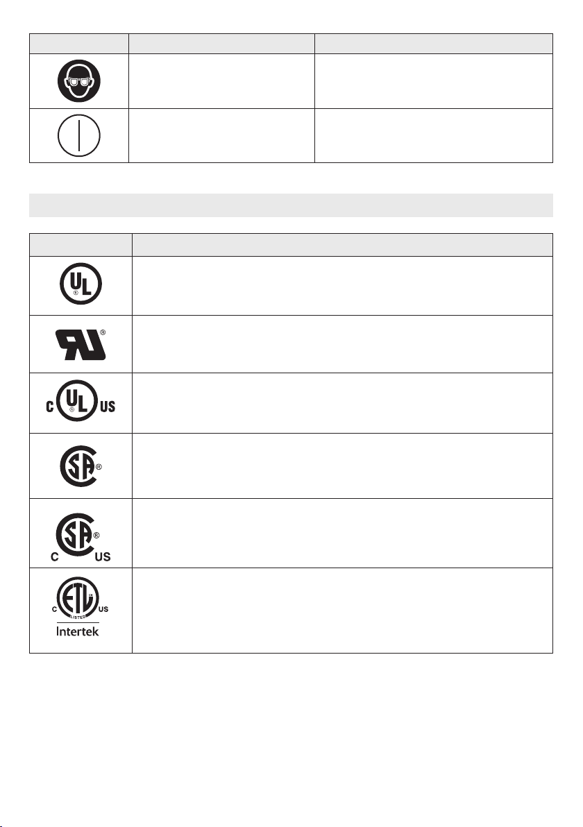
SYMBOLS (CERTIFICATION INFORMATION)
Symbol Designation/Explanation
This symbol designates that this tool is listed by Underwriters Laboratories.
This symbol designates that this component is recognized by Underwriters
Laboratories.
This symbol designates that this tool is listed by Underwriters Laboratories, to
United States and Canadian Standards.
This symbol designates that this tool is listed by the Canadian Standards
Association.
This symbol designates that this tool is listed by the Canadian Standards
Association, to United States and Canadian Standards.
This symbol designates that this tool is listed by the Intertek Testing Services,
to United States and Canadian Standards.
-8-
FUNCTIONAL DESCRIPTIONS AND SPECIFICATIONS
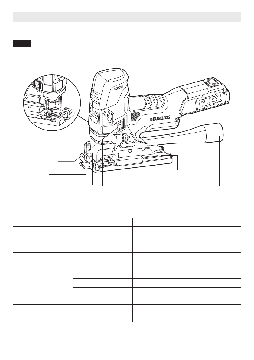
Cordless Jig Saw
Fig. 1
LED Light
Right-Side
Guide Roller
Right On/Off Switch
Left On/Off Switch
Splinter Guard
Chip Guard Blade Release
Lever
Orbit-Control
Lever
Cover Plate Dust Collection
Port
Base
Hex Wrench /
Storage
Speed Control PanelLED Light Switch
Blade Holder
Model No. FX2221
Rated Voltage 24 V d.c.
Speed Range (strokes per minute) 800 – 3500 /min
Speed Settings 1, 2, 3, 4, Auto
Stroke Length 1" (25mm)
Pendulum Stroke Off plus 3 orbit settings
Maximum Depth of Cut
(with appropriate blade)
Wood 4.72" (120mm)
Aluminum 0.79" (20mm)
Steel 0.39" (10mm)
Bevel Angle 0° – 45° both sides
Recommended operating temperature -4 – 104°F (-20 – 40℃)
Recommended storage temperature < 122℉ (< 50℃)
-9-
ASSEMBLY
WARNING Detach the battery pack from
the tool before making any
assembly, adjustments or changing
accessories. Such preventive safety measures
reduce the risk of starting the tool accidentally.
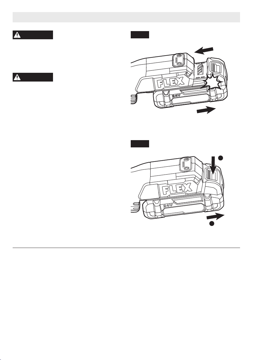
TO ATTACH/DETACH BATTERY PACK
WARNING Always switch off the tool
before attaching or
detaching of the battery pack.
To attach the battery pack:
Align the raised rib on the battery pack with the
grooves on the tool, and then slide the battery
pack onto the tool (Fig. 2)
NOTICE: When placing the battery pack on the
tool, be sure that the raised rib on the battery
pack aligns with the groove inside the tool
and that the latches snap into place properly.
Improper attachment of the battery pack can
cause damage to internal components.
To detach the battery pack:
Depress the battery-release button, located
on the front of the battery pack, to release the
battery pack. Pull the battery pack out and
remove it from the tool (Fig. 3).
1
2
Fig. 3
Fig. 2
click

-10-
INSTALLING AND REMOVING THE SAW
BLADE
The tool can only accept most commonly
available T-shank blades.
To install the saw blade (Fig. 4):
a. Insert the blade (with its teeth facing the
cutting direction) into the slot of the blade
holder as far as the blade can go.
b. Pull down on the blade to verify that the blade
is securely locked in place.
NOTICE: When inserting the saw blade, the
back of the blade must rest in the groove of the
guide roller.
To remove the saw blade (Fig. 5):
a. Turn the blade release lever as shown and
remove the saw blade.
b. Release the blade release lever.
WARNING Always wear protective
gloves when removing the
saw blade from the tool. The saw blade is
sharp and may be hot after prolonged use.
Fig. 5
Fig. 4
Guide Roller
Table of contents
Languages:
Other Flex Cordless Saw manuals


